PART 1211 - SAFETY STANDARD FOR AUTOMATIC RESIDENTIAL GARAGE DOOR OPERATORS
Subpart A - The Standard
Source:
57 FR 60455, Dec. 21, 1992, unless otherwise noted.
§ 1211.1 Effective date.
This standard applies to all residential garage door operators manufactured on or after January 1, 1993 for sale in the United States.
§ 1211.2 Definition.
As used in this part 1211: Residential garage door operator means a vehicular door operator which:
(a) Serves a residential building of one to four single family units;
(b) Is rated 600 volts or less; and
(c) Is intended to be employed in ordinary locations in accordance with NFPA 70 (incorporated by reference, see § 1211.32).
[57 FR 60455, Dec. 21, 1992, as amended at 62 FR 46667, Sept. 4, 1997; 65 FR 70657, Nov. 27, 2000; 81 FR 20228, Apr. 7, 2016]
§ 1211.3 Units of measurement.
If a value for measurement is followed by a value in other units, in parentheses, the second value may be only approximate. The first stated value is the requirement.
[57 FR 60455, Dec. 21, 1992, as amended at 65 FR 70657, Nov. 27, 2000]
§ 1211.4 General requirements for protection against risk of injury.
(a) If an automatically reset protective device is employed, automatic restarting of a motor shall not result in a risk of injury to persons.
(b) A residential garage door operator is considered to comply with the requirement in paragraph (a) of this section if some means is provided to prevent the motor from restarting when the protector closes.
(c) An electronic or solid-state circuit that performs a back-up, limiting, or other function intended to reduce the risk of fire, electric shock, or injury to persons, including entrapment protection circuits, shall comply with the requirements in UL 991 (incorporated by reference, see § 1211.40), including environmental and stress tests appropriate to the intended usage of the end-product. Exception: A control or electronic circuit that complies with Supplement SA of UL 325-2017 (incorporated by reference, see § 1211.40) is considered to fulfill this requirement.
[57 FR 60455, Dec. 21, 1992, as amended at 62 FR 46667, Sept. 4, 1997; 65 FR 70657, Nov. 27, 2000; 81 FR 20228, Apr. 7, 2016; 83 FR 32568, July 13, 2018]
§ 1211.5 General testing parameters.
(a) The following test parameters are to be used in the investigation of the circuit covered by § 1211.4(c) for compliance with either, UL 991, or Supplement SA of UL 325-2017 (incorporated by reference, see § 1211.40):
(1) With regard to electrical supervision of critical components, an operator being inoperative with respect to closing movement of the door meets the criteria for trouble indication.
(2) A field strength of 3 volts per meter is to be used for the Radiated EMI Test.
(3) The Composite Operational and Cycling Test is to be used for 14 days at temperature extremes of minus 35 °Celsius (minus 31 °F) and 70 °C (158 °F).
(4) Exposure Class H5 is to be used for the Humidity Test.
(5) A vibration level of 5g is to be used for the Vibration Test.
(6) When a Computational Investigation is conducted, λp shall not be greater than 6 failures/106 hours for the entire system. For external secondary entrapment protection devices or systems that are sold separately, λp shall not be greater than 0 failures/106 hours. For internal secondary entrapment protection devices or systems whether or not they are sold separately, λp shall not be greater than 0 failures/106 hours. The operational test is conducted for 14 days. An external secondary entrapment protection device or system that is sold separately, and that has a λp greater than 0 failures/106 hours meets the intent of the requirement when for the combination of the operator and the specified external secondary entrapment protection device or system λp does not exceed 6 failures/106 hours. See § 1211.18(j) through (l).
(7) When the Demonstrated Method Test is conducted, the multiplier is to be based on the continuous usage level, and a minimum of 24 units for a minimum of 24 hours per unit are to be tested.
(8) The Endurance test is to be conducted concurrently with the Operational test. The control shall perform its intended function while being conditioned for fourteen days in an ambient air temperature of 60 °C (140 °F), or 10 °C (18 °F) greater than the operating temperature of the control, whichever is higher. During the test, the control is to be operated in a manner representing the opening and closing of the door at a rate of one open-close operation per minute.
(9) For the Electrical Fast Transient Burst Test, test level 3 is to be used for residential garage door operators.
(b) In the evaluation of entrapment protection circuits used in residential garage door operators, the critical condition flow chart shown in figure 1 to subpart A shall be used:
(1) To conduct a failure-mode and effect analysis (FMEA);
(2) In investigating the performance during the Environmental Stress Tests;
(3) During the Power Cycling Safety for Tests in accordance with UL 991 (incorporated by reference, see § 1211.40); and
(4) During evaluation of the circuit to the requirements of Supplement SA of UL 325-2017 (incorporated by reference, see § 1211.40).
[57 FR 60455, Dec. 21, 1992, as amended at 62 FR 46667, Sept. 4, 1997; 65 FR 70657, Nov. 27, 2000; 81 FR 20228, Apr. 7, 2016; 83 FR 32568, July 13, 2018]
§ 1211.6 General entrapment protection requirements.
(a) A residential garage door operator system shall be provided with inherent primary entrapment protection that complies with the requirements as specified in § 1211.7.
(b) In addition to the inherent primary entrapment protection as required by paragraph (a) of this section, a vertically moving residential garage door operator shall comply with one of the following:
(1) Shall be constructed to:
(i) Require constant pressure on a control intended to be installed and activated within line of sight of the door to lower the door;
(ii) Reverse direction and open the door to the upmost position when constant pressure on a control is removed prior to operator reaching its lower limit, and
(iii) Limit a portable transmitter, when supplied, to function only to cause the operator to open the door;
(2) Shall be provided with a means for connection of an external secondary entrapment protection device as described in § 1211.8 (a) and (c) through (e), as applicable to vertically moving doors; or
(3)
(i) Shall be provided with an inherent secondary entrapment protection device as described in §§ 1211.8(a) and (f), 1211.10, and 1211.12 and is:
(A) A combination sectional overhead garage door operator system as described in § 1211.6(c); and
(B) For use only with vertically moving garage doors.
(ii) With respect to § 1211.6(b)(3)(i)(A), trolley-driven operators do not meet the definition of a combination sectional overhead garage door operator system.
(c) In the case of a vertically moving combination sectional overhead garage door operator system, the door shall comply with the requirements in ANSI/DASMA 102 (incorporated by reference, see § 1211.40).
(d) In addition to the inherent primary entrapment protection as required by § 1211.6(a), a horizontally sliding residential garage door operator shall comply with one of the following:
(1) Shall be constructed to:
(i) Require constant pressure on a control to close the door;
(ii) Reverse direction and open the door a minimum of 2 in (50.8 mm) when constant pressure on a control is removed prior to operator reaching its position limit; and
(iii) Stop the door if a second obstruction is detected in the reverse direction.
(2) Shall be provided with a means for connection of an external secondary entrapment protection device for each leading edge as described in § 1211.8(c) through (e), as applicable to horizontally moving doors.
(e) A mechanical switch or a relay used in an entrapment protection circuit of an operator shall withstand 100,000 cycles of operation controlling a load no less severe (voltage, current, power factor, inrush and similar ratings) than it controls in the operator, and shall function normally upon completion of the test.
(f) In addition to complying with paragraph (e) of this section, in the event of a malfunction of a switch or relay (open or short) described in paragraph (c) of this section results in loss of any entrapment protection required by § 1211.7(a), § 1211.7(b)(7), § 1211.7(c)(7), § 1211.8(a), or § 1211.8(b), the door operator shall become inoperative at the end of the opening or closing operation, the door operator shall move the door to, and stay within, 1 foot (305 mm) of the uppermost position.
[81 FR 20228, Apr. 7, 2016, as amended at 83 FR 32569, July 13, 2018]
§ 1211.7 Inherent primary entrapment protection requirements.
(a) General requirements. A vertically moving residential garage door operator system shall be supplied with inherent primary entrapment protection that complies with the requirements as specified in paragraph (b) of this section. A horizontally sliding residential garage door operator system shall be supplied with inherent primary entrapment protection that complies with the requirements as specified in paragraph (c) of this section.
(b) Inherent primary entrapment protection, vertically moving doors.
(1)
(i) For a vertically moving residential garage door operator system, other than for the first 1 foot (305mm) of door travel from the full upmost position both with and without any secondary external entrapment protection device functional, the operator of a downward moving residential garage door shall initiate reversal of the door within 2 seconds of contact with the obstruction as specified in subparagraph (b)(3) of this section. After reversing the door, the operator shall return the door to, and stop at, the full upmost position. Compliance shall be determined in accordance with paragraphs (b)(3) through (10) of this section.
(ii) The door operator is not required to return the door to, and stop the door at, the full upmost position when the operator senses a second obstruction during the upward travel.
(iii) The door operator is not required to return the door to, and stop the door at, the full upmost position when a control is actuated to stop the door during the upward travel—but the door can not be moved downward until the operator reverses the door a minimum of 2 inches (50.8 mm).
(2) The test shall be performed on a representative operating system installed in accordance with the manufacturer's installation instructions with the operator exerting a 25-lbf (111.21-N) pull or its rated pull, whichever is greater.
(3)
(i) A solid object is to be placed on the floor of the test installation and at various heights under the edge of the door and located in line with the driving point of the operator. When tested on the floor, the object shall be 1 inch (25.4 mm) high. In the test installation, the bottom edge of the door under the driving force of the operator is to be against the floor when the door is fully closed.
(ii) For operators other than those attached to the door, a solid object is not required to be located in line with the driving point of the operator. The solid object is to be located at points at the center, and within 1 foot of each end of the door.
(iii) To test operators for compliance with requirements in paragraphs (b)(1)(iii), (b)(7)(iii), and (b)(8)(iii) of this section and § 1211.13(c), a solid rectangular object measuring 4 inches (102 mm) high by 6 inches (152 mm) wide by a minimum of 6 inches (152 mm)long is to be placed on the floor of the test installation to provide a 4-inch (102 mm) high obstruction when operated from a partially open position.
(4) An operator is to be tested for compliance with paragraph (b)(1) of this section for 50 open-and-close cycles of operation while the operator is connected to the type of residential garage door with which it is intended to be used or with the doors specified in paragraph (b)(6) of this section. For an operator having a force adjustment on the operator, the force is to be adjusted to the maximum setting or at the setting that represents the most severe operating condition. Any accessories having an effect on the intended operation of entrapment protection functions that are intended for use with the operator, are to be attached and the test is to be repeated for one additional cycle.
(5) For an operator that is to be adjusted (limit and force) according to instructions supplied with the operator, the operator is to be tested for 10 additional obstruction cycles using the solid object described in paragraph (b)(3) of this section at the maximum setting or at the setting that represents the most severe operating condition.
(6) For an operator that is intended to be used with more than one type of door, one sample of the operator is to be tested on a sectional door with a curved track and one sample is to be tested on a one-piece door with jamb hardware and no track. For an operator that is not intended for use on either or both types of doors, a one-piece door with track hardware or a one-piece door with pivot hardware shall be used for the tests. For an operator that is intended for use with a specifically dedicated door or doors, a representative door or doors shall be used for the tests. See the marking requirements at § 1211.18.
(7)
(i) An operator, employing an inherent entrapment protection system that measures or monitors the actual position of the door, shall initiate reversal of the door and shall return the door to, and stop the door at, the full upmost position in the event the inherent door operating “profile” of the door differs from the originally set parameters. The entrapment protection system shall measure or monitor the position of the door at increments not greater than 1 inch (25.4 mm).
(ii) The door operator is not required to return the door to, and stop the door at, the full upmost position when an inherent entrapment circuit senses an obstruction during the upward travel.
(iii) The door operator is not required to return the door to, and stop the door at, the full upmost position when a control is actuated to stop the door during the upward travel—but the door can not be moved downward until the operator reverses the door a minimum of 2 inches (50.8 mm).
(8)
(i) An operator, using an inherent entrapment protection system that does not measure or monitor the actual position of the door, shall initiate reversal of the door and shall return the door, to and stop the door at the full upmost position, when the lower limiting device is not actuated in 30 seconds or less following the initiation of the close cycle.
(ii) The door operator is not required to return the door to, and stop the door at, the full upmost position when an inherent entrapment circuit senses an obstruction during the upward travel. When the door is stopped manually during its descent, the 30 seconds shall be measured from the resumption of the close cycle.
(iii) The door operator is not required to return the door to, and stop the door at, the full upmost position when a control is actuated to stop the door during the upward travel—but the door can not be moved downward until the operator reverses the door a minimum of 2 inches (50.8 mm). When the door is stopped manually during its descent, the 30 seconds shall be measured from the resumption of the close cycle.
(9) To determine compliance with paragraph (b)(7) or (8) of this section, an operator is to be subjected to 10 open-and-close cycles of operation while connected to the door or doors specified in paragraphs (b)(4) and (6) of this section. The cycles are not required to be consecutive. Motor cooling-off periods during the test meet the intent of the requirement. The means supplied to comply with the requirement in paragraph (b)(1) of this section and § 1211.8(a) or (b) are to be defeated during the test. An obstructing object is to be used so that the door is not capable of activating a lower limiting device.
(10) During the closing cycle referred to in paragraph (b)(9) of this section, the system providing compliance with paragraphs (b)(1) and (7) of this section or paragraphs (b)(1) and (8) of this section shall function regardless of a short- or open-circuit anywhere in any low-voltage external wiring, any external entrapment devices, or any other external component.
(c) Inherent primary entrapment protection, horizontally sliding doors.
(1)
(i) For a horizontally sliding residential garage door operator system, other than for the first 1 foot (305mm) of door travel from the full closed position both with and without any external entrapment protection device functional, the operator of a closing residential garage door shall initiate reversal of the door within 2 seconds of contact with the obstruction as specified in paragraph (c)(3) of this section. After reversing the door, the operator shall open the door a minimum of 2 inches (50.8 mm) from the edge of the obstruction. Compliance shall be determined in accordance with paragraphs (c)(2) through (10) of this section.
(ii) The door operator is not required to open the door a minimum 2 inches (50.8 mm) when the operator senses a second obstruction during the reversing travel.
(iii) The door operator is not required to open the door a minimum 2 inches (50.8 mm) when a control is actuated to stop the door during movement towards the open position—but the door can not be moved towards the closed position until the operator reverses the door a minimum of 2 inches (50.8 mm).
(2) The test shall be performed on a representative operating system installed in accordance with the manufacturer's installation instructions with the operator exerting a 25-lbf (111.21-N) pull or its rated pull, whichever is greater.
(3)
(i) A solid object is to be placed on the floor of the test installation and rigidly supported within the bottom track and then repeated with the solid object placed on the floor and rigidly supported external to the track. The test shall then be repeated with the solid object rigidly supported at heights of 1 ft (305 mm), 3 ft (914 mm), 5 ft (1524 mm), and within 1 ft (305 mm) of the top edge. The object shall be 1 inch (25.4 mm) in width.
(ii) For operators other than those attached to the door, a solid object is not required to be located in line with the driving point of the operator. The solid object is to be located at points at the center and within 1 ft of each end of the door opening.
(iii) To test operators for compliance with paragraphs (c)(1)(iii), (c)(7)(iii), and (c)(8)(iii) of this section, and § 1211.13(c), a solid rectangular object measuring 4 inches (102 mm) high by 6 inches (152 mm) wide by a minimum of 6 in (152 mm) long is to be placed on the floor of the test installation to provide a 4 in (102 mm) high obstruction when operated from a partially open position with the test repeated with the bottom edge of the obstruction rigidly supported at heights of 1 ft (305 mm), 3ft (914 mm), 5ft (1524 mm), and within 1 ft (305 mm) of the top edge.
(4) An operator is to be tested for compliance with paragraph (c)(1) of this section for 50 open-and-close cycles of operation while the operator is connected to the type of residential garage door with which it is intended to be used or with the doors specified in paragraph (c)(6) of this section. For an operator having a force adjustment on the operator, the force is to be adjusted to the maximum setting or at the setting that represents the most severe operating condition. Any accessories having an effect on the intended operation of entrapment protection functions that are intended for use with the operator, are to be attached and the test is to be repeated for one additional cycle.
(5) For an operator that is to be adjusted (limit and force) according to instructions supplied with the operator, the operator is to be tested for 10 additional obstruction cycles using the solid object described in paragraph (c)(3) of this section at the maximum setting or at the setting that represents the most severe operating condition.
(6) For an operator that is intended to be used with more than one type of door, one sample of the operator is to be tested on a sectional door with a curved track and one sample is to be tested on a one-piece door with jamb hardware and no track. For an operator that is not intended for use on either or both of these types of doors, a one-piece door with track hardware or a one-piece door with pivot hardware shall be used for the tests. For an operator that is intended for use with a specifically dedicated door or doors, a representative door or doors shall be used for the tests. See the marking requirements in § 1211.18.
(7)
(i) An operator, employing an inherent entrapment protection control that measures or monitors the actual position of the door, shall initiate reversal of the door and shall return the door to, and stop the door at, the fully open position in the event the inherent door operation “profile” of the door differs from the originally set parameters. The system shall measure or monitor the position of the door at increments not greater than 1 inch (25.4 mm).
(ii) The door operator is not required to open the door a minimum 2 inches (50.8 mm) when an inherent entrapment circuit senses an obstruction during the reversing travel.
(iii) The door operator is not required to open the door a minimum 2 inches (50.8 mm) when a control is actuated to stop the door during the opening direction—but the door can not be moved in the closing direction until the operator reverses the door a minimum of 2 inches (50.8 mm).
(8)
(i) An operator, using an inherent entrapment protection system that does not measure or monitor the actual position of the door, shall initiate reversal of the door and shall open the door a minimum 2 inches (50.8 mm) when the closed position limit device is not actuated within 30 seconds or less following the initiation of the close cycle.
(ii) The door operator is not required to open the door a minimum 2 inches (50.8 mm) when an inherent entrapment circuit senses an obstruction during the reversing travel.
(iii) The door operator is not required to open the door a minimum 2 inches (50.8 mm) when a control is actuated to stop the door during the opening direction—but the door can not be moved in the closing direction until the operator has reversed the door a minimum of 2 inches (50.8 mm). When the door is stopped manually during its closing, the 30 seconds shall be measured from the resumption of the close cycle.
(9) To determine compliance with paragraph (c)(7) or (8) of this section, an operator is to be subjected to 10 open-and-close cycles of operation while connected to the door or doors specified in paragraphs (c)(4) and (6) of this section. The cycles are not required to be consecutive. Motor cooling-off periods during the test meet the intent of the requirement. The means supplied to comply with paragraph (c)(1) of this section and § 1211.8(b) are to be inoperative or defeated during the test. An obstructing object is to be used so that the door is not capable of activating a position limiting device.
(10) During the closing cycle referred to in paragraph (c)(9) of this section, the system providing compliance with paragraphs (c)(1) and (7) of this section or paragraphs (c)(1) and (8) of this section shall function regardless of a short- or open-circuit anywhere in any low-voltage external wiring, any external entrapment devices, or any other external component.
[81 FR 20228, Apr. 7, 2016, as amended at 83 FR 32569, July 13, 2018]
§ 1211.8 Secondary entrapment protection requirements.
(a)
(1) For a vertically moving door operator, a secondary entrapment protection device supplied with, or as an accessory to, an operator shall consist of:
(i) An external photoelectric sensor that when activated results in an operator that is closing a door to reverse direction of the door, returns the door to, and stops the door at the fully open position, and the sensor prevents an operator from closing an open door,
(ii) An external edge sensor installed on the edge of the door that, when activated as tested per § 1211.12(a)(4)(1) results in an operator that is closing a door to reverse direction of the door, returns the door to, and stops the door at the fully open position, and the sensor prevents an operator from closing an open door,
(iii) An inherent door sensor independent of the system used to comply with § 1211.7 that, when activated, results in an operator that is closing a door to reverse direction of the door and the sensor prevents an operator from closing an open door, or
(iv) Any other external or internal device that provides entrapment protection equivalent to paragraph (a)(1)(i), (ii), or (iii) of this section.
(2) The door operator is not required to return the door to, and stop the door at, the fully open position when an inherent entrapment circuit senses an obstruction during the opening travel.
(3) The door operator is not required to return the door to, and stop the door at, the fully open position when a control is actuated to stop the door during the opening travel—but the door cannot be moved towards the closing direction until the operator has reversed the door a minimum of 2 inches (50.8 mm).
(b) For horizontal sliding garage door operators, a secondary entrapment protection device supplied with, or as an accessory to, an operator shall consist of:
(1) An external photoelectric sensor that, when activated, results in an operator that is closing or opening a door to reverse direction of the door for a minimum of 2 inches (50.8 mm); or
(2) An external edge sensor installed on the edge of the door that, when activated as tested per § 1211.12 (a)(4)(2), results in an operator that is closing or opening a door to reverse direction of the door for a minimum of 2 inches (50.8 mm).
(c) With respect to paragraphs (a) and (b) of this section, the operator shall monitor for the presence and correct operation of the device at least once during each close cycle. Should the device not be present or a fault condition occurs which precludes the sensing of an obstruction, including an interruption of the wireless signal to the wireless device or an open or short circuit in the wiring that connects an external entrapment protection device to the operator and device's supply source, the operator shall be constructed such that:
(1) For a vertically moving door, the closing door shall open and an open door shall not close more than 1 foot (305 mm) below the upmost position;
(2) For a horizontally sliding door, the door shall not move in the opening or closing direction; or
(3) The operator shall function as required by § 1211.6(b)(1).
(d) An external entrapment protection device or system, when employing a wireless control, shall comply with paragraph (e) of this section when installed at its farthest distance from the operator as recommended in the installation instructions.
(e) An external entrapment protection device shall comply with the applicable requirements in §§ 1211.10, 1211.11, and 1211.12.
(f) An inherent secondary entrapment protection device described in § 1211.6(b)(3) shall comply with the applicable requirements in § 1211.13. Software used in an inherent entrapment protection device shall comply with UL 1998 (incorporated by reference, see § 1211.40).
[81 FR 20230, Apr. 7, 2016, as amended at 83 FR 32569, July 13, 2018]
§ 1211.9 Additional entrapment protection requirements.
(a) A means to manually detach the door operator from the door shall be supplied. The gripping surface (handle) shall be colored red and shall be easily distinguishable from the rest of the operator. It shall be capable of being adjusted to a height of 6 feet (1.8 m) above the garage floor when the operator is installed according to the instructions specified in § 1211.16(a)(2). The means shall be constructed so that a hand firmly gripping it and applying a maximum of 50 pounds (223 N) of force shall detach the operator with the door obstructed in the down position. The obstructing object, as described in § 1211.7(b)(3)(i), is to be located in several different positions. A marking with instructions for detaching the operator shall be provided as required by § 1211.17(a), (b), and (j), as applicable.
(b) A means to manually detach the door operator from the door is not required for a door operator that is not directly attached to the door and that controls movement of the door so that:
(1) The door is capable of being moved open from any position other than the last (closing) 2 inches (50.8 mm) of travel, and
(2) The door is capable of being moved to the 2-inch (50.8-mm) point from any position between closed and the 2-inch (50.8-mm) point.
(c) Actuation of a control that initiates movement of a door shall stop and may reverse the door on the closing cycle. On the opening cycle, actuation of a control shall stop the door but not reverse it.
(d) An operator shall be constructed so that adjustment of limit, force or other user controls and connection of external entrapment protection devices can be accomplished without exposing normally enclosed live parts or wiring.
[57 FR 60455, Dec. 21, 1992, as amended at 65 FR 70658, Nov. 27, 2000; 81 FR 20231, Apr. 7, 2016]
§ 1211.10 Requirements for all entrapment protection devices.
(a) General requirements.
(1) An external entrapment protection device shall perform its intended function when tested in accordance with paragraphs (a)(2) through (4) of this section.
(2) The device is to be installed in the intended manner and its terminals connected to circuits of the door operator as indicated by the installation instructions.
(3) The device is to be installed and tested at minimum and maximum heights and widths representative of recommended ranges specified in the installation instructions. For doors, if not specified, devices are to be tested on a minimum 7 foot (2.1 m) wide door and maximum 20 foot (6.1 m) wide door.
(4) If powered by a separate source of power, the power-input supply terminals are to be connected to supply circuits of rated voltage and frequency.
(5) An external entrapment protection device requiring alignment, such as a photoelectric sensor, shall be provided with a means, such as a visual indicator, to show proper alignment and operation of the device.
(b) Current protection test.
(1) There shall be no damage to the entrapment protection circuitry if low voltage field-wiring terminals or leads are shortened or miswired to adjacent terminals.
(2) To determine compliance with paragraph (b)(1) of this section, an external entrapment protection device is to be connected to a door operator or other source of power in the intended manner, after which all connections to low voltage terminals or leads are to be reversed as pairs, reversed individually, or connected to any low voltage lead or adjacent terminal.
(3) After restoring the connections in the intended manner:
(i) A photoelectric sensor shall comply with the Normal Operation tests per § 1211.11(a) through (c); and
(ii) An edge sensor shall comply with the applicable Normal Operation test, per § 1211.12(a).
(c) Splash test.
(1) An external entrapment protection device intended to be installed inside a garage 3 feet or less above the floor shall withstand a water exposure as described in paragraph (c)(2) of this section without resulting in a risk of electric shock and shall function as intended, per paragraph (c)(3) of this section. After exposure, the external surface of the device may be dried before determining its functionality.
(2) External entrapment protection devices are to be indirectly sprayed using a hose having the free end fitted with a nozzle as illustrated in Figure 2 to subpart A and connected to a water supply capable of maintaining a flow rate of 5 gallons (19 liters) per minute as measured at the outlet orifice of the nozzle. The water from the hose is to be played, from all sides and at any angle against the floor under the device in such a manner most likely to cause water to splash the enclosure of electric components. However, the nozzle is not to be brought closer than 10 feet (3.05 m) horizontally to the device. The water is to be sprayed for 1 minute.
(3) After drying the external surface of the device:
(i) A photoelectric sensor shall comply with the Normal Operation Tests per § 1211.11(a) through (c); and
(ii) An edge sensor shall comply with the applicable Normal Operation Test, per § 1211.12(a).
(iii) There shall be no water on uninsulated live parts of a line voltage circuit.
(d) Ultraviolet light exposure test. A polymeric material used as a functional part of a device that is exposed to outdoor weather conditions shall comply with the Ultraviolet Light Exposure Test described in UL 746C (incorporated by reference, see § 1211.40).
(e) Resistance to impact test.
(1) An external entrapment protection device employing a polymeric or elastomeric material as a functional part shall be subjected to the impact test specified in paragraph (e)(2) of this section. As a result of the test:
(i) There shall be no cracking or breaking of the part; and
(ii) The part shall operate as intended, per paragraph (e)(4) of this section at room temperature, or, if dislodged after the test, but not cracked or broken, is capable of being restored to its original condition. Exception: If a part is cracked or broken, as an alternative, it may be subjected to the Splash Tests, per paragraph (c) of this section, after the impact test. After the water exposure tests, the device shall either:
(A) Operate as intended per paragraph (e)(4) of this section; or
(B) Shut down safely (i.e. provide an obstruction signal to the door).
(2) Samples of the external entrapment protection device are to be subjected to the Resistance to Impact Test described in UL 746C (incorporated by reference, see § 1211.40). The external entrapment protection device is to be subjected to 5 foot-pound (6.8 J) impacts. Three samples are to be tested, each sample being subjected to three impacts at different points.
(3) In lieu of conducting the room temperature test described in paragraph (e)(2) of this section, each of three samples of a device exposed to outdoor weather when the door is in the closed position are to be cooled to a temperature of minus 31.0 ±3.6 °F (minus 35.0 ±2.0 °C) and maintained at this temperature for 3 hours. Three samples of a device employed inside the garage are to be cooled to a temperature of 32.0 °F (0.0 °C) and maintained at this temperature for 3 hours. While the sample is still cold, the samples shall be subject to the test described in paragraph (e)(2) of this section, and shall comply with paragraph (e)(1)(i) of this section. After determining compliance with paragraph (e)(1)(i) of this section, the sample shall be allowed to return to room temperature, and then shall comply with paragraph (e)(1)(ii) of this section.
(4) To determine compliance with paragraph (e)(1)(ii) of this section:
(i) A photoelectric sensor shall comply with the Normal Operation tests per § 1211.11(a) through (c); and
(ii) An edge sensor shall comply with the applicable Normal Operation Test, per § 1211.12(a).
(f) External entrapment protection devices with wireless control —
(1) Initial test set-up.
(i) For a wireless device intended to be powered by a non-rechargeable battery, a fully charged battery shall be installed per the instructions or markings on the product. See § 1211.16 (a)(7).
(ii) An entrapment protection device or system employing a wireless control, or separately supplied for, shall be installed per the manufacturer's instructions.
(2) Radiated immunity test.
(i) An external entrapment protection device when employing wireless control shall operate as specified in § 1211.8(a) through (e) as applicable; or is rendered inoperative (any case in which the operator will not complete a full cycle, open and close, of travel) when tested in accordance with paragraph (f)(2)(ii) of this section.
(ii) Compliance to paragraph (f)(2)(i) of this section is verified by simulating an obstruction during the period of the electric field strength test of § 1211.4(c).
(g) Battery test for wireless devices.
(1) An external entrapment protection device when employing a battery powered wireless control shall operate as specified in § 1211.8(a) through (e) as applicable; or is rendered inoperative (any case in which the operator will not complete a full cycle, open and close, of travel) when tested in accordance with paragraph (g)(2) of this section.
(2) Compliance with paragraph (g)(1) of this section shall be verified with battery charge at the following levels:
(i) Fully charged; and
(ii) Discharged per the manufacturer's recommendations to the wireless device's lowest operational voltage.
(3) An external entrapment protection device employing a battery powered wireless device operating under conditions with a fully discharged battery or when the battery is discharged sufficiently to cause the device or system to render the moving door inoperative, shall be considered a single point fault for complying with §§ 1211.5(b) and 1211.8(c).
(h) Ambient light test for wireless device with IR communication.
(1) An external entrapment protection device, when employing an IR communication shall operate as specified in § 1211.8(a) through (e) as applicable; or is rendered inoperative (any case in which the operator will not complete a full cycle, open and close, of travel) when subjected to ambient light impinging at an angle of 15 to 20 degrees from the axis of the beam when tested in accordance with paragraph (h)(2) of this section.
(2) An external entrapment protection device when employing an IR communication shall be set up at maximum range per paragraph (h)(1) of this section. The ambient light test described in § 1211.11(e)(2) shall be conducted with the light source impinging on each IR receiver, one at a time that is part of the wireless control system between the external entrapment protection device and the operator.
[81 FR 20231, Apr. 7, 2016, as amended at 83 FR 32569, July 13, 2018]
§ 1211.11 Requirements for photoelectric sensors.
(a) Normal operation test. When installed as described in § 1211.10(a)(1) through (4), a photoelectric sensor of a vertically moving door shall sense an obstruction as described in paragraph (c) of this section that is to be placed on the floor at three points over the width of the door opening, at distances of 1 foot (305 mm) from each end and the midpoint.
(b) Normal operation test—Horizontally moving door. When installed as described in § 1211.10(a)(1) through (4), a photoelectric sensor of a horizontally moving door shall be tested per paragraph (c) of this section that is to be placed on a level surface within the path of the moving door. The sensor is to be tested with the obstruction at a total of five different locations over the height of the door or gate opening. The locations shall include distances 1 in (25.4 mm) from each end, 1 ft (305 mm) from each end, and the midpoint.
(c) Normal operation test—Obstruction. The obstruction noted in paragraphs (a) and (b) of this section shall consist of a white vertical surface 6 inches (152 mm) high by 12 inches (305 mm) long. The obstruction is to be centered in the opening perpendicular to the plane of the door when in the closed position. See Figure 3 to subpart A.
(d) Sensitivity test.
(1) When installed as described in § 1211.10(a)(1) through (4), a photoelectric sensor shall sense the presence of a moving object when tested according to paragraph (d)(2) of this section.
(2) The moving object is to consist of a 17⁄8 inch (47.6 mm) diameter cylindrical rod, 341⁄2 inches (876 mm) long, with the axis point being 34 inches (864 mm) from the end. The axis point is to be fixed at a point centered directly above the beam of the photoelectric sensor 36 inches (914 mm) above the floor. The photoelectric sensor is to be mounted at the highest position as recommended by the manufacturer. The rod is to be swung as a pendulum through the photoelectric sensor's beam from a position 45 degrees from the plane of the door when in the closed position. See Figure 4 to subpart A.
(3) The test described in paragraph (d)(2) of this section is to be conducted at three points over the width of the door opening, at distances of 1 foot (305 mm) from each end and the midpoint.
(4) When the test fixture of Figure 4 to subpart A, prior to conduct of the test, interferes with the photoelectric sensor detection zone, the tests per paragraphs (d)(1) through (4) of this section may be conducted instead per paragraph (f)(4) of this section.
(e) Ambient light test.
(1) A photoelectric sensor shall operate as specified in § 1211.8(a) and (c) when subjected to ambient light impinging at an angle of 15 to 20 degrees from the axis of the beam when tested according to paragraph (e)(2) of this section and, if appropriate, paragraph (e)(3) of this section.
(2) To determine compliance with paragraph (e)(1) of this section, a 500 watt incandescent or equivalent minimum rated, 3600K or lower color rated flood lamp is to be energized from a 120-volt, 60-hertz source. The lamp is to be positioned 5 feet from the front of the receiver and aimed directly at the sensor at an angle of 15 to 20 degrees from the axis of the beam. See Figure 5 to subpart A.
(3) If the photoelectric sensor uses a reflector, this test is to be repeated with the lamp aimed at the reflector.
(4) During the test conditions described in paragraphs (e)(2) and (e)(3) of this section, a photoelectric sensor shall comply with the normal operation test requirements described in paragraph (a) of this section, and
(i) A photoelectric sensor shall comply with sensitivity test requirements described in paragraph (d) of this section, and
(ii) An edge sensor shall comply with the normal operation test requirements described in § 1211.12.
(f) Photoelectric sensor vertical arrays.
(1) A vertical array shall be tested as required by paragraphs (a) through (e) of this section, except as noted in paragraphs (f)(2) through (5) of this section.
(2) The array shall comply with the Normal Operation tests specified in paragraphs (a) through (c) of this section, with the solid obstruction placed on the floor. In addition, the obstruction shall be placed at various locations over the height of the light curtain array in accordance with the light curtain coverage area per the manufacturer's instructions.
(3) In conducting the tests specified in paragraphs (a) through (c) of this section, when the product includes a blanking function whereby the light array is located directly in-line with the path of the door travel, and the door system is intended to detect any obstruction other than one in the “next” successive position that the door is programmed to travel, the obstruction is placed at any location other than the next successive door position expected by the system.
(4) The array shall comply with the Sensitivity Test specified in paragraph (d) of this section, except that the edge of the pendulum nearest to the array is to be located 2 in. (50.8 mm) from one side of the plane of the array, rather than directly above one photoelectric sensor pair. For vertical arrays, this test need only be conducted with the test pendulum at the vertical height indicated in paragraph (d)(2) of this section.
(5) When conducting the Ambient Light Test specified in paragraph (e) of this section, the position of the light source shall be aligned per paragraph (e)(2) of this section based on the axis of the lowest beam or detection zone. This arrangement shall be used to determine compliance with the requirements specified in paragraph (f)(2) of this section (with the obstruction at the floor level) and paragraph (f)(4) of this section, which are the only conditions for which the ambient light is required to be applied.
[81 FR 20232, Apr. 7, 2016]
§ 1211.12 Requirements for edge sensors.
(a) Normal operation test.
(1) When installed on a representative residential door edge, an edge sensor shall actuate upon the application of a 15 pounds (66.7 N) or less force in the direction of the application. For an edge sensor intended to be used on a sectional door, the force is to be applied by the longitudinal edge of a 17⁄8 inch (47.6 mm) diameter cylinder placed across the switch so that the axis is perpendicular to the plane of the door. For an edge sensor intended to be used on a one piece door, the force is to be applied so that the axis is at an angle 30 degrees from the direction perpendicular to the plane of the door. See figure 6 to subpart A.
(2) With respect to the test of paragraph (a)(1) of this section, the test is to be repeated at various representative points of the edge sensor across the width of the door.
(3) Exception: The edge sensor need not be sensitive to actuation two inches (50.4 mm) or less from each end of the intended width of the door opening.
(4)
(i) An edge sensor, when installed on a representative door, shall actuate upon the application of a 15 lbf (66.7 N) or less force in the direction of the application when tested at room temperature 25 °C ±2 °C (77 °F ±3.6 °F) and, additionally, when intended for use with gate operators, shall actuate at 40 lbf (177.9 N) or less force when tested at −35 °C ±2 °C (−31 °F ±3.6 °F).
(A) For an edge sensor intended to be used on a sectional door, the force is to be applied by the longitudinal edge of a 17⁄8 in (47.6 mm) diameter cylinder placed across the sensor so that the axis is perpendicular to plane of the door. See Figures 6A and 6B to this subpart.
(B) For an edge sensor intended to be used on a one piece door, swinging door, or swinging gate, the force is to be applied so that the axis is at an angle 30 degrees from the direction perpendicular to the plane of the door. See Figures 6C and 6D to this subpart.
(C) For an edge sensor that wraps around the leading edge of a swinging one-piece door, providing activation in both directions of travel, the force is to be applied so that the axis is at an angle 30 degrees from the direction perpendicular to both the closing direction and the opening direction. See Figure 6E to this subpart.
(ii) With respect to the Edge Sensor Test specified in paragraph (a)(4)(ii) of this section, the test is to be repeated at various representative points of the edge sensor across the length of the edge sensor. See Figures 6F and 6G to this subpart.
(5) Residential garage door operators.
(i) For vertically moving residential garage door operators intended to be used with an external edge sensor, with reference to 32.3.1(b), a 15⁄8 in by 31⁄2 in (41.3 mm by 88.9 mm) solid rectangular object not less than 6 in (152 mm) long is to be fixed in an immobile position at the fully closed position with the longitudinal axis perpendicular to the edge of the door. The 15⁄8 in (41.3 mm) side of the obstruction facing the leading edge is to contact the moving door at various points along the width of the door. See Figure 6H to this subpart.
(ii) For horizontally moving residential garage door operators intended to be used with an external edge sensor, with reference to 32.3.2(b), a 15⁄8 in by 31⁄2 in (41.3 mm by 88.9 mm) solid rectangular object not less than 6 in (152 mm) long is to be fixed in an immobile position with the longitudinal axis perpendicular to the edge of the door. The 15⁄8 in (41.3 mm) side of the obstruction facing the leading edge is to contact the moving door at various points along the leading edge of the door. The same object is then to be arranged to contact the moving door at various points along the trailing edge of the door. See Figure 6I to this subpart.
(b) Endurance test. An edge sensor system and associated components shall withstand 30,000 cycles of mechanical operation without failure. For this test, the edge sensor is to be cycled by the repetitive application of the force as described in paragraph (a)(4)(i) of this section but at room temperature only. The force is to be applied to the same location for the entire test. For an edge sensor system employing integral electric contact strips, this test shall be conducted with the contacts connected to a load no less severe than it controls in the operator. For the last 50 cycles of operation, the sensor shall function as intended when connected to an operator.
(c) Elastomeric material conditioning test.
(1) An elastomeric material used as a functional part of an edge sensor shall function as intended when subjected to:
(i) Accelerated Aging Test of Gaskets, stated in paragraph (c)(3) of this section,
(ii) Compliance to the Standard for Gaskets and Seals, UL 157, fulfills this requirement (see paragraph (c)(2) of this section for UL contact information); and
(iii) Puncture Resistance Test, stated in paragraph (d) of this section.
(2) An elastomeric material used for a functional part that is exposed to outdoor weather conditions when the door is in the closed position shall have physical properties as specified in the table to subpart A after being conditioned in accordance with the Ultraviolet Light Exposure Test described in UL 746C (incorporated by reference, see § 1211.40).
(3) Rubber compounds forming gaskets that are depended upon for protection from rain shall have physical properties as specified in table 1, before and after conditioning for 168 hours in an air-circulating oven at 70 °C (158 °F).
(d) Puncture resistance test.
(1) After being subjected to the tests described in paragraph (d)(2) or (3) of this section, an elastomeric material that is a functional part of an edge sensor shall:
(i) Not be damaged in a manner that would adversely affect the intended operation of the edge sensor, and
(ii) Maintain enclosure integrity if it serves to reduce the likelihood of contamination of electrical contacts.
(2) For a vertically moving door, a sample of the edge sensor is to be installed in the intended manner on a representative door edge. The probe described in figure 7 to subpart A is to be applied with a 20 pound-force (89 N) to any point on the sensor that is 3 inches (76 mm) or less above the floor is to be applied in the direction specified in the Edge Sensor Normal Operation Test, Figure 6A or 6C to subpart A as applicable. The test is to be repeated on three locations on each surface of the sensor being tested.
(3) For horizontally sliding doors, sample of the edge sensor is to be installed in the intended manner on a representative door edge. The probe described in figure 7 to subpart A is to be applied with a 20 lbf (89 N) to any point on the sensor when the door is within 3 in (76 mm) of its fully open position and within 3 in (76 mm) of any stationary wall. For each type of door, the force is to be applied in the direction specified in the Edge Sensor Normal Operation Test, Figure 6B to subpart A. The test is to be repeated on three locations on each surface of the sensor being tested.
[57 FR 60455, Dec. 21, 1992, as amended at 62 FR 46667, Sept. 4, 1997; 65 FR 70659, Nov. 27, 2000; 81 FR 20233, Apr. 7, 2016; 83 FR 32569, July 13, 2018]
§ 1211.13 Inherent force activated secondary door sensors.
(a) General.
(1) A force activated door sensor of a door system installed according to the installation instructions shall actuate in accordance with paragraphs (b) through (f) of this section, which are to be conducted in sequence on a single system sample, except for the separate test sequences of paragraph (a)(2) of this section.
(2) The system shall actuate with the maximum and minimum specifications of the door, operator, and hardware.
(3) Tests conducted per paragraphs (b) through (f) of this section shall be performed with the force exerted by a drive adjusted to its highest value if the force can be adjusted by the user during use or user maintenance.
(4) The test cylinder referred to in paragraph (b)(7) of this section shall be a 17⁄8 in (47.6 mm) diameter cylinder placed under the door so that the axis is perpendicular to the plane of the door. See figure 6A to subpart A.
(5) The measuring device referred to in paragraph (b)(1) of this section shall:
(i) Have an accuracy of ±1%;
(ii) Have a rise and fall time not exceeding 5 ms;
(iii) Have the equivalence of a spring constant of 2855 lb/in ±285 lb/in (500 N/mm, ±50 N/mm);
(iv) Be placed on a rigid, level surface; and
(v) Have a rigid plate with a diameter of 3.1 in (80 mm).
(vi) See paragraph (a)(6) of this section for test equipment alternatives for force measurements at 1 ft (305 mm) or greater for the tests conducted per paragraphs (b) and (d) of this section.
(6) With regard to the alternative test equipment referred to in paragraph (a)(5)(vi) of this section, the test device described in paragraph (b)(5) of this section for force measurements at 1 foot (305 mm) or greater shall be:
(i) A spring constant means such as specified in paragraph (a)(5) of this section;
(ii) A gravity based weight displacing means that suspends a weight off its supporting surface upon exceeding 15 lbf (67 N) such as the example shown in figures 8 through 10 of this subpart if the equipment described in paragraph (a)(5) of this section is applied before the tests specified in paragraph (c) of this section and after the tests specified in paragraph (d) of this section at the 1 ft (305 mm) height specified in paragraph (b)(6) of this section; or
(iii) The equivalent requirements of paragraphs (a)(6)(i) or (ii) of this section.
(7) The cycles specified in paragraph (d) of this section are not required to be consecutive. Continuous operation of the motor without cooling is not required.
(b) Closing force test.
(1) The door shall stop and reverse within 2 seconds after contacting the obstruction. The door shall apply the following forces at the locations noted in paragraph (b)(2) of this section:
(i) 90 lbf (400 N) or less average during the first 0.75 seconds after 15 lbf (67 N) is exceeded from initial impact; and
(ii) 15 lbf (67 N) or less from 0.75 seconds after 15 lbf (67 N) is exceeded from initial impact until the door reverses.
(2) The test referred to in paragraph (b)(1) of this section shall be conducted at the following test height and locations along the edge of the door:
(i) The center point, at a height of 2 in (50.8) from the floor;
(ii) Within 1 ft (305 mm) of the end of the door, at a height of 2 in (50.8) from the floor; and
(iii) Within 1 ft (305 mm) of the other end of the door, at a height of 2 in (50.8) from the floor.
(3) The maximum force specified in paragraph (b)(1) of this section shall be tested by the door applying a force against the longitudinal edge of the test cylinder described in paragraph (a)(4) of this section.
(4) The equipment used to measure force for the test described in paragraph (b)(1) of this section shall be in accordance with the requirements of paragraph (a)(5) of this section.
(5) The door shall stop and reverse within 2 seconds after contacting the obstruction. The door shall apply a load of 15 lbf (67 N) or less in the closing direction along the path of door travel at the locations noted in paragraph (b)(6) of this section.
(6) The test described in paragraph (b)(5) of this section shall be conducted at the following points along the edge of the door:
(i) At the center at heights of 1 ft, 3 ft, and 5 ft (305 mm, 914 mm and 1.52 m) from the floor;
(ii) Within 1 ft (305 mm) of the end of the door, at heights of 1 ft, 3 ft, and 5 ft from the floor; and
(iii) Within 1 ft of the other end of the door at heights of 1 ft, 3 ft, and 5 ft from the floor.
(7) The maximum force described in paragraph (b)(5) of this section shall be tested by the door applying a force against the longitudinal edge of the test cylinder as described in paragraph (a)(4) of this section.
(8) The equipment used to measure forces for the test described in paragraph (b)(1) of this section shall be in accordance with the requirements of paragraph (a)(5) or (6) of this section.
(c) Opening force test.
(1) The door shall stop within 2 seconds after a weight of 44 lb (20 kg) is applied to the door.
(2) The test described in paragraph (c)(1) of this section shall be conducted with the door starting from the fully closed position and at heights of approximately 1 ft, 3 ft, and 5 ft (305 mm, 914 mm and 1.52 m) from the floor.
(3) Test weight(s) shall be applied to sections of the door that are vertical in the initial stopped position for each test height prior to operator activation.
(d) Fifty cycle test.
(1) With the door(s) at the test point(s) determined by the tests described in paragraphs (b) and (c) of this section to be most severe with respect to both reversal time and force, the door system shall function as intended after 50 cycles of operation. After the last cycle, the system shall complete one additional cycle of opening the door to its fully open condition and closing the door to its fully closed position.
(2) The tests described in paragraphs (b) and (c) of this section shall be repeated upon completion of cycling test.
(e) Adjustment of door weight. At the point determined by the test described in paragraph (b)(5) of this section to be the most severe, weight is to be added to the door in 5.0 pound (2.26 Kg) increments and the tests of paragraphs (b) and (c) of this section are to be repeated until a total of 15.0 pounds (66.72 N) has been added to the door. Before performing each test cycle, the door is to be cycled 2 times to update the profile. Similarly, starting from normal weight plus 15.0 pounds, the tests described in paragraphs (b) and (c) of this section are to be repeated by subtracting weight in 5.0 pound increments until a total of 15.0 pounds has been subtracted from the door.
(f) Obstruction test. For a door traveling in the downward direction, when an inherent secondary entrapment protection device senses an obstruction and initiates a reversal, any control activation shall not move the door downward until the operator reverses the door a minimum of 2 inches (50.8 mm). The test is to be performed as described in § 1211.7(b)(3)(iii). The system may be initially manually re-profiled for the purpose of this test.
[81 FR 20233, Apr. 7, 2016, as amended at 83 FR 32570, July 13, 2018]
§ 1211.14 Unattended operation requirements.
(a) General requirements.
(1) A residential garage door operator or system may permit unattended operation to close a garage door, provided the operator system complies with the additional requirements of paragraphs (b) through (e) of this section.
(2) Unattended operation shall not be permitted on one-piece garage doors or swinging garage doors. An operator intended for use with both sectional doors and one-piece or swinging doors that have an unattended operation close feature shall identify that the unattended operation closing feature is only permitted to be enabled when installed with a sectional door by complying with:
(i) The installation instructions stated in § 1211.16(b)(1)(ii);
(ii) The markings specified in § 1211.17(h); and
(iii) The carton markings specified in § 1211.18(m) when the carton references the unattended operation close feature.
(b) Operator system. The operator system shall require one or more intentional actions to enable unattended operation, such as setting a power head switch or wall-control switch. For an accessory requiring installation and set-up in order to enable unattended operation, the installation and set-up may be considered satisfying this requirement.
(c) Alarm signal.
(1) The operator system shall provide an audible and visual alarm signal.
(2) The alarm shall signal for a minimum of 5 seconds before any unattended closing door movement.
(3) The audible signal shall be heard within the confines of a garage. The audio alarm signals for the alarm specified in paragraph (c)(1) of this section shall be generated by devices such as bells, horns, sirens, or buzzers. The signal shall have a frequency in the range of 700 to 3400 Hz, either a cycle of the sound level pulsations of 4 to 5 per second or one continuous tone, a sound level at least 45 dB 10 ft (305 cm) in front of the device over the voltage range of operation.
(4) The visual alarm signal described in paragraph (c)(1) of this section shall be visible within the confines of a garage using a flashing light of at least 40 watt incandescent or 360 lumens. The flash rate shall be at least once per second, with a duration of 100 ms to 900 ms, for the duration of the alarm.
(d) Controls.
(1) During the pre-motion signaling period defined in paragraph (c)(2) of this section, activation of any user door control (e.g., wall control, wireless remote, keypad) shall prevent the pending unattended door movement. Door movement resulting from activation of a user door control is not prohibited.
(2) Upon activation of a user door control during unattended door movement, the door shall stop, and may reverse the door on the closing cycle. On the opening cycle, activation of a user door control shall stop the door but not reverse it.
(3) If an unattended door travelling in the closing direction is stopped and reversed by an entrapment protection device, the operator system shall be permitted one additional unattended operation attempt to close the door.
(4) After two attempts per paragraph (d)(3) of this section, the operator system shall suspend unattended operation. The operator system shall require a renewed, intended input, via user door control (e.g., wall control wireless remote, keypad) other than the unattended activation device, prior to re-enabling unattended operation.
(e) Entrapment protection. For a moving door, entrapment protection shall comply with §§ 1211.7 and 1211.8.
(f) Unattended operation control accessory —
(1) General. A residential garage door operator control accessory shall be permitted to be supplied separate from the operator, and may permit unattended operation to close a garage door, provided the control accessory complies with the additional requirements of paragraphs (f)(2) through (6) of this section. Exception: Unattended operation shall not be permitted on one-piece garage doors or swinging garage doors. A control accessory that has an unattended operation close feature shall identify that the unattended operation closing feature is only permitted to be enabled when installed with a sectional door by complying with:
(i) The installation instructions of § 1211.16 (b)(1)(ii);
(ii) The markings of § 1211.17(h); and
(iii) the carton markings of § 1211.18(m).
(2) Operator system. The control accessory shall require one or more intentional actions to enable unattended operation to function when connected to an operator system, such as setting a power head switch or wall-control switch. For an accessory requiring installation and set-up in order to enable unattended operation, the installation and set-up may be considered satisfying this requirement.
(3) Alarm signal.
(i) The control accessory alone or in combination with the operator system shall provide an audible and visual alarm signal.
(ii) The alarm shall signal for a minimum of 5 seconds before any unattended closing door movement, or before any door movement if the next direction of door travel cannot be determined.
(iii) The audible signal shall be heard within the confines of a garage. The audio alarm signals for the alarm specified in paragraph (f)(3)(i) of this section shall be generated by devices such as bells, horns, sirens, or buzzers. The signal shall have a frequency in the range of 700 to 3400 Hz, either a cycle of the sound level pulsations of 4 to 5 per second or one continuous tone, a sound level at least 45 dB 10 ft (305 cm) in front of the device over the voltage range of operation.
(iv) The visual alarm signal of paragraph (f)(3)(i) of this section shall be visible within the confines of a garage using a flashing light of at least 40 watt incandescent or 360 lumens.
(v) When the visual alarm or the audio alarm, or both, are external to the control accessory and are not part of main operator unit, the control accessory shall monitor for the connection of and proper operation of both the visual and audible alarms, prior to initiating door travel.
(4) Controls.
(i) During the pre-motion signaling period defined in paragraph (f)(3)(ii) of this section, activation of any user door control (e.g. wall control, wireless remote, keypad) shall prevent the pending unattended door movement. Door movement resulting from activation of a user door control is not prohibited.
(ii) Upon activation of a user door control during unattended door movement:
(A) The operator shall function in the same manner as if the control accessory were not present;
(B) The control accessory shall not interfere with, override, or alter the normal operation of the operator; and
(C) The door shall stop, and may reverse the door on the closing cycle. On the opening cycle, activation of a user door control shall stop the door but not reverse it.
(iii) If an unattended door travelling in the closing direction is stopped and reversed by an entrapment protection device, the control accessory alone or in combination with the operator system shall be permitted one additional unattended operation attempt to close the door.
(iv) After two attempts per paragraph (d)(3) of this section, the control accessory alone or in combination with the operator system shall suspend unattended operation. The control accessory alone or in combination with the operator system shall require a renewed, intended input, via user door control (e.g., wall control, wireless remote, keypad) other than the unattended activation device, prior to re-enabling unattended operation.
(5) Entrapment protection.
(i) The control accessory shall not interfere with, override, or alter any entrapment protection features of the operator or system per §§ 1211.7 and 1211.8. A control accessory that only provides a momentary signal (wired or wireless) to start the door is considered to comply with this requirement.
(ii) A control accessory shall only be used with an operator when the combination of the operator and the control accessory comply with the applicable entrapment protection features including:
(A) Inherent Primary Entrapment Protection, in accordance with § 1211.7;
(B) Secondary Entrapment Protection, in accordance with § 1211.8.
(iii) A control accessory shall be marked to indicate “For use only with garage door operators complying with UL 325, manufactured after ____,” or, “For use only with the following garage door operators:____.” The date (e.g., “1993,” “February 21, 2008”), or the additional information provided in the blank shall be added by the accessory manufacturer such that the combination of the control and operator(s) it is intended for use with complies with paragraph (f)(5)(ii) of this section. This marking shall appear on the packaging and on the product, and shall be repeated in the instructions accompanying the accessory.
(iv) To comply with paragraph (f)(5)(ii) of this section a control accessory shall comply with one or more of the following:
(A) Not be capable of operating when connected to an operator that is not compliant with paragraph (f)(5)(ii) of this section;
(B) Be restricted to function only with specific operators, such that the combination of the control and the operator are compliant with paragraph (f)(5)(ii) of this section;
(C) Provide additional functionality to an operator or system such that when operating via the control accessory, the combination of the control accessory and the operator complies with paragraph (f)(5)(ii) of this section;
(D) Be marked to indicate as indicated in paragraph (f)(5)(ii) of this section.
(6) Instructions and markings.
(i) The control accessory shall be provided with instructions as follows:
(A) Instructions per § 1211.16, as applicable.
(B) Instructions that repeat any warning or cautionary product markings and field labels required below.
(ii) The control accessory shall be provided with markings as follows:
(A) Markings on the product per § 1211.18, as applicable.
(B) In lieu of § 1211.18(m), the product package shall be marked with the following or equivalent:
| “WARNING: To reduce the risk of injury to persons—Only enable [+] feature when installed with sectional door.”, where + is the unattended operation closing function, or “WARNING: To reduce the risk of injury to persons—Do not use this device with one-piece doors or swinging doors.” |
(C) On the package or the product—any other markings related to use of the control with specific operators, per paragraph (f)(5)(iii) of this section.
(iii) The control accessory shall be provided with a label for field installation as required by § 1211.17(c) through (g), including but not limited to § 1211.17(g)(2)(v).
[81 FR 20234, Apr. 7, 2016, as amended at 83 FR 32570, July 13, 2018]
§ 1211.15 Vertically moving combination rigid one-piece overhead residential garage door and operator system.
(a) A vertically moving combination rigid one-piece overhead residential garage door and operator system shall comply with the applicable residential garage door operator requirements in this standard and shall additionally comply with the following:
(1) The speed of the door edge during the opening or closing motion shall not exceed 6 in (152 mm) per second.
(2) The system shall be supplied with two additional independent secondary entrapment protection devices complying with Secondary Entrapment Protection, § 1211.8. When photoelectric sensors are used, a minimum of two sensors in addition to a third secondary device shall be supplied. The instructions shall state that one photoelectric sensor shall be positioned to comply with § 1211.11 and the other(s) shall be positioned on the left and right sides of the door to detect solid objects that would be within the space where the door moves as it opens or closes.
(3) A means to manually detach both door operators from the door shall be provided. For systems where the mechanical drive is located on a wall adjacent to the door, the manual detachment means is not required to comply with § 1211.9(a). Instead, the manual detachment means shall be located 5 ft (1.52 m) above the floor, shall not require a torque of more than 5 ft-lb (6.78 N-m) to initiate disconnection when the door is obstructed, and shall be clearly marked with operating instructions adjacent to the mechanism. The gripping surface (handle) shall be colored red and shall be distinguishable from the rest of the operator. The marking which includes instructions for detaching the operator shall be provided in accordance with § 1211.17(a), (b), and (j) as applicable.
(4) A means (interlock) shall be supplied to de-energize the operator whenever the operator is manually detached from the door.
(5) A means (interlock) shall be supplied to de-energize the operator whenever an operable window or access (service) door that is mounted in the garage door is opened perpendicular to the surface of the garage door.
(6) The door shall not move outward from the exterior wall surface during the opening or closing cycle.
(7) The moving parts of the door or door system (mounting hardware, track assembly, and components that make up the door) shall be guarded.
(8) A horizontal track assembly, including installation hardware, shall support a dead load equal to the door weight when the door is in the horizontal position.
(9) Instructions for the installation of operable windows and access (service) doors and the interlocks specified in paragraph (a)(5) of this section shall be supplied with the operator.
(b) [Reserved]
[81 FR 20235, Apr. 7, 2016]
§ 1211.16 Instruction manual.
(a) General.
(1) A residential garage door operator shall be provided with an instruction manual. The instruction manual shall give complete instructions for the installation, operation, and user maintenance of the operator.
(2) Instructions that clearly detail installation and adjustment procedures required to effect proper operation of the safety means provided shall be provided with each door operator.
(3) A residential garage door or door operator shall be provided with complete and specific instructions for the correct adjustment of the control mechanism and the need for periodic checking and, if needed, adjustment of the control mechanism so as to maintain satisfactory operation of the door.
(4) The instruction manual shall include the important instructions specified in paragraphs (b)(1) and (2) of this section. All required text shall be legible and contrast with the background. Upper case letters of required text shall be no less than 5⁄64 inch (2.0 mm) high and lower case letters shall be no less than 1⁄16 inch (1.6 mm) high. Heading such as “Important Installation Instructions,” “Important Safety Instructions,” “Save These Instructions” and the words “Warning—To reduce the risk of severe injury or death to persons:” shall be in letters no less than 3⁄16 inch (4.8 mm) high.
(5) The instructions listed in paragraphs (b)(1) and (2) of this section shall be in the exact words specified or shall be in equally definitive terminology to those specified. No substitutes shall be used for the word “Warning.” The items may be numbered. The first and last items specified in paragraph (b)(2) of this section shall be first and last respectively. Other important and precautionary items considered appropriate by the manufacturer may be inserted.
(6) The instructions listed in paragraph (b)(1) of this section shall be located immediately prior to the installation instructions. The instructions listed in paragraph (b)(2) of this section shall be located immediately prior to user operation and maintenance instructions. In each case, the instructions shall be separate in format from other detailed instructions related to installation, operation and maintenance of the operator. All instructions, except installation instructions, shall be a permanent part of the manual(s).
(7) For an operator or system provided with an external entrapment protection device requiring a non-rechargeable battery, instructions shall be provided with the operator and/or the device for:
(i) The rating, size, number, and type of battery(s) to be used; and
(ii) The proper insertion, polarity, orientation, and replacement of the battery(s).
(8) For an operator or system provided with an external entrapment protection device or system utilizing wireless control, instructions shall be provided with the operator and/or the device for:
(i) The proper method of configuring and initializing the wireless communication link between device and operator;
(ii) The proper orientation, antenna positioning, and mounting location with regard to maintaining communication link between device and operator;
(iii) The maximum range at which the wireless device will operate; and
(iv) The proper location of the device where the transmission of the signals are not obstructed or impeded by building structures, natural landscaping or similar obstruction.
(9) When provided with a detachable supply cord, the operator instructions shall contain complete details concerning proper selection of the power supply cord replacement.
(10) The installation, operation, and maintenance instructions may be provided in electronic read-only media format only, such as CD-ROM, USB flash drive, or company Web site, if the following instructions are additionally provided with the operator in an instruction sheet, manual, booklet, or similar printed material:
(i) Residential garage doors and door operators, instructions of this section, as applicable.
(ii) [Reserved]
(11) The printed instruction material referenced in this section shall contain detailed instructions of how to obtain a printed copy of the material contained in electronic format.
(12) All printed instruction material referenced in this section shall also be provided in the electronic read-only media format.
(13) Instructions of a combination sectional overhead garage door operator system shall specify:
(i) The operator by manufacturer and model;
(ii) The door(s) by manufacturer(s), model(s), and maximum and minimum door width and height required for compliance to § 1211.6(a) and (c); and
(iii) Hardware required for compliance to § 1211.6(a) and (c).
(14) Installation and maintenance instructions of a combination sectional overhead garage door operator system shall indicate how to properly counter-balance the door.
(b) Specific required instructions for residential garage door operators and systems.
(1)
(i) The Installation Instructions shall include the following instructions:
Important Installation Instructions
Warning—To reduce the risk of severe injury or death:
1. Read and follow all Installation Instructions.
2. Install only a properly balanced garage door. An improperly balanced door could cause severe injury. Have a qualified service person make repairs to cables, spring assemblies and other hardware before installing opener.
3. Remove all pull ropes and remove, or make inoperative, all locks connected to the garage door before installing opener.
4. Where possible, install door opener 7 feet or more above the floor. For products requiring an emergency release, mount the emergency release within reach, but at least 6 feet above the floor and avoiding contact with vehicles to avoid accidental release.
5. Do not connect opener to source of power until instructed to do so.
6. Locate control button: (a) Within sight of door, (b) at a minimum height of 5 feet above floors, landings, steps, or any other adjacent walking surface so small children cannot reach it, and (c) away from all moving parts of the door.
7. Install Entrapment Warning Label next to the control button in a prominent location. Install the Emergency Release Marking. Attach the marking on or next to the emergency release.
8. After installing opener, the door must reverse when it contacts a 11⁄2 inch high object (or a 2 by 4 board laid flat) on the floor.
9. For products having a manual release, instruct the end user on the operation of the manual release.
10. For horizontally sliding doors, Item 2 shall be replaced with “Have a qualified service person make repairs and hardware adjustments before installing the opener.”
(ii) In accordance with § 1211.14(a)(2), the installation instructions in paragraph (b)(1) of this section for a residential garage door operator intended for use with both sectional and one-piece door that has an unattended operation close feature shall comply with paragraph (b)(1) of this section and include:
“WARNING: To reduce the risk of injury to persons—Only enable [+] feature when installed with a sectional door,” where + is the unattended operation function.
(iii) Exception: For operators that automatically sense one piece door operation, the warning in paragraph (b)(1)(ii) of this section is not required.
(iv) For residential garage door operators that do not have permanent connection of the wiring system, the installation instructions shall include the following or equivalent text:
“This operator not equipped for permanent wiring. Contact licensed electrician to install a suitable receptacle if one is not available.”
(2) The User Instructions shall include the following instructions:
IMPORTANT SAFETY INSTRUCTIONS
Warning—To reduce the risk of severe injury or death:
1. READ AND FOLLOW ALL INSTRUCTIONS.
2. Never let children operate, or play with door controls. Keep the remote control away from children.
3. Always keep the moving door in sight and away from people and objects until it is completely closed. No one should cross the path of the moving door.
4. NEVER GO UNDER A STOPPED PARTIALLY OPEN DOOR.
5. Test door opener monthly. The garage door MUST reverse on contact with a 11⁄2 inch object (or a 2 by 4 board laid flat) on the floor. After adjusting either the force or the limit of travel, retest the door opener. Failure to adjust the opener properly may cause severe injury or death.
6. For products requiring an emergency release, if possible, use the emergency release only when the door is closed. Use caution when using this release with the door open. Weak or broken springs may allow the door to fall rapidly, causing injury or death.
7. KEEP GARAGE DOOR PROPERLY BALANCE. See user's manual. An improperly balanced door could cause severe injury or death. Have a qualified service person make repairs to cables, spring assemblies and other hardware.
8. For operator systems equipped with an unattended operation feature, the following statement shall be included: “This operator system is equipped with an unattended operation feature. The door could move unexpectedly. NO ONE SHOULD CROSS THE PATH OF THE MOVING DOOR.”
9. SAVE THESE INSTRUCTIONS.
10. For horizontally moving doors, Item 4 shall be replaced with “NEVER GO THROUGH A STOPPED, PARTIALLY OPEN DOOR”.
11. For horizontally moving doors, Item 6 is not required.
12. For horizontally moving doors, Item 7 shall be replaced with “Have a qualified service person make repairs and hardware adjustments before installing the opener.”
13. The installation instructions provided with a combination rigid one-piece overhead residential garage door and operator system shall specify the locations where attachments to the horizontal track shall be made for the purpose of supporting the track.
[81 FR 20235, Apr. 7, 2016]
§ 1211.17 Field-installed labels.
(a) A residential garage door operator shall be provided with labels for field installation and constructed as specified in paragraphs (c) through (i) of this section. The labels shall be acceptable for permanent installation. The instruction manual shall specify where the labels are to be located.
(b) If labels secured by adhesive are used, the instruction shall specify that an additional mechanical means shall be used to secure the labels to surfaces to which the adhesive will not adhere.
(c) A residential garage door operator shall be provided with a cautionary label intended for permanent installation to identify the possible risk of entrapment. The instruction manual shall direct that the label be affixed near the wall-mounted control button.
(d) The label required in accordance with paragraph (c) of this section shall be in a vertical layout with three panels:
(1) A signal word panel,
(2) A pictorial panel, and
(3) A message panel, with adjacent panels delineated from each other by a horizontal black line. The entire label shall be surrounded by a black border and shall measure at least 5 inches (127 mm) wide by 61⁄4 inches (159 mm) long overall.
(e) The signal word panel as specified in paragraph (d) of this section shall contain the word “WARNING,” in uppercase letters, preceded by a safety alert symbol consisting of an orange exclamation mark on a black solid equilateral triangle background with the point of the triangle oriented upward. The word “WARNING” and the safety alert symbol shall be centered on one line and shall be in black letters at least 7⁄16 inch (11.1 mm) high on an orange background.
(f) The pictorial panel as specified in paragraph (d) of this section shall be positioned between the signal word panel and the message panel. The pictorial shall be black on a white background and shall clearly depict a child running toward or under a garage door. A red prohibition symbol (slash, oriented from the upper left to the lower right, through a circle) shall be superimposed over, and totally surround, the pictorial. The pictorial shall have an overall diameter of 1-71⁄8 inch (47.6 mm) minimum.
(g) The message panel as specified in paragraph (d) of this section shall include the following text or an equivalent wording:
(1) Possible Risk and Consequence Statement—“There is a risk of a child becoming trapped under an automatic garage door resulting in severe injury or death.”
(2) Avoidance Statements—
(i) “Do not allow children to walk or run under a closing door.”
(ii) “Do not allow children to operate door operator controls.”
(iii) “Always keep a closing door within sight.”
(iv) “In the event a person is trapped under the door, push the control button or use the emergency release.” For products not having an emergency release use instead “In the event a person is trapped under the door, push the control button.”
(v) For products equipped with an unattended operation feature, the instructions shall include the following: “This operator system is equipped with an unattended operation feature. The door could move unexpectedly.”
(3) Instructions—
(i) “Test Door Operator Monthly: Use a 11⁄2 inch thick object placed on the floor under the closing door. In the event the door does not reverse upon contact, adjust, repair, or replace the operator.”
(ii) Additional instructions on not removing or painting over the label, mounting the label adjacent to the wall control, and mounting the wall control out of children's reach shall be provided. These additional instruction shall be in less prominent lettering than those in paragraph (g)(3)(i) of this section.
(h)
(1) In accordance with § 1211.14(a)(2), the instructions of a residential garage door operator intended for use with both sectional doors and either one-piece or swinging doors and are provided with an unattended operation feature shall comply with paragraph (g) of this section and include the following under the avoidance statements of paragraph (g)(2) of this section:
“Only enable [+] feature when installed with a sectional door.”, or equivalent, where + is the unattended operation closing function.
(2) For operators that automatically sense one piece door operation, this warning is not required.
(i) The lettering of the message panel described in paragraph (g) of this section shall be black on a white background and shall be sans serif letters in combinations of upper case and lower case letters. The upper case letters of the Possible Risk and Consequence Statements and Avoidance Statements shall be 1⁄8 inch (3.18 mm) high minimum. The lettering of the Possible Risk and Consequence Statement shall be in italics, underlined, bold, or the like, and shall be double spaced from the Avoidance Statements. All other instructions shall be in letters less prominent than the Possible Risk and Consequence Statements and shall be separated with at least a single space between individual instructions.
(j) Except for door operators complying with § 1211.9(b), a residential garage door operator shall be provided with a cautionary marking attached to or adjacent at all times to the means provided to detach the operator from the garage door. The marking shall include the following statement or the equivalent: “If the door becomes obstructed, detach door from operator as follows: (The method to detach the operator shall be shown on the marking.)”
(k) Both the operator and the door that comprise a combination sectional overhead garage door operator system shall be provided with permanent labels. The labels shall contain the following statement or the equivalent: “WARNING: THIS OPERATOR AND DOOR FUNCTION AS A SYSTEM. IF EITHER THE DOOR OR THE HARDWARE MUST BE REPLACED, THE REPLACEMENT DOOR OR HARDWARE MUST BE IDENTICAL TO THE ORIGINAL EQUIPMENT WITH RESPECT TO MANUFACTURER AND MODEL TO MAINTAIN THE SAFETY OF THE SYSTEM. SEE INSTRUCTION MANUAL.” The marking shall be visible to the user after installation without the need to remove any covers.
(l) A label specified in paragraph (m) of this section when intended to be affixed during installation shall:
(1) Be provided with the operator or door assembly; and
(2) Have installation instructions of how and where to install the label so that it is visible to the user after installation.
(m) The operator of a combination sectional overhead garage door operator system shall be provided with a permanent marking that contains the following statement or the equivalent: “NO USER SERVICEABLE PARTS INSIDE.”
[57 FR 60455, Dec. 21, 1992. Redesignated and amended at 65 FR 70659, Nov. 27, 2000. Further redesignated and amended at 81 FR 20234, 20237, Apr. 7, 2016]
§ 1211.18 UL marking requirements.
(a) Unless specifically excepted, marking required in this standard shall be permanent. Ink-printed and stenciled markings, decalcomania labels, and pressure sensitive labels are among the types of marking that are considered acceptable if they are acceptably applied and are of good quality.
(b) Except as provided below, a garage door operator shall be plainly marked, at a location where the marking will be readily visible—after installation, in the case of a permanently connected appliance—with:
(1) The manufacturer's name, trademark, or other descriptive marking by which the organization responsible for the product may be identified—hereinafter referred to as the manufacturer's name;
(2) The catalog number or the equivalent;
(3) The voltage, frequency, and input in amperes, VA, or watts. The ampere or VA rating shall be included unless the full-load power factor is 80 percent or more, or, for a cord-connected appliance, unless the rating is 50 W or less. The number of phases shall be indicated when an appliance is for use on a polyphase circuit; and
(4) The date or other dating period of manufacture not exceeding any three consecutive months.
(c) The date code repetition cycle shall not be less than 20 years.
(d) Exception No. 1: The manufacturer's identification may be in a traceable code if the operator is identified by the brand or trademark owned by a private labeler.
(e) Exception No. 2: The date of manufacture may be abbreviated or in an established or otherwise accepted code.
(f) Exception No 3: The input in amperes or watts may be shown as part of the motor nameplate, if the appliance employs a single motor, the nameplate is readily visible after the appliance has been installed.
(g) If a manufacturer produces or assembles operators at more than one factory, each finished operator shall have a distinctive marking, which may be in code, to identify it as the product of a particular factory.
(h) The carton and the instruction manual for an operator shall be marked with the word “WARNING” and the following or the equivalent: “To reduce the risk of injury to persons—Use this operator only with (a) ___ door(s).”
(i) For products with user adjustments, a residential garage door operator shall be marked with the word “WARNING” and the following or equivalent, “Risk of entrapment. After adjusting either the force or limits of travel adjustments, insure that the door reverses on a 11⁄2 inch (or a 2 by 4 board laid flat) high obstruction on the floor.” This marking shall be located where visible to the user when making the adjustments.
(j) For a separately supplied accessory, including external entrapment protection device, the instructions, packaging, or marking on the product shall indicate the accessory manufacturer's name and or model number and the type of appliance or appliances with which it is intended to be used—such as a residential garage door operator. Additionally, installation instructions, accompanying specifications sheet, or packaging of the accessory shall identify the appliance or appliances with which it is intended to be used by specifying the manufacturer's name and catalog or model number or by any other positive means to serve the identification purpose.
(k) An appliance provided with terminals or connectors for connection of a separately supplied accessory, such as an external entrapment protection device or system, shall be marked to identify the accessory intended to be connected to the terminals or connectors. The accessory identification shall be by manufacturer's name and catalog or model number or other means to allow for the identification of accessories intended for use with the appliance.
(l) With reference to paragraph (k) of this section, instructions for installing a separately supplied accessory shall be provided. A statement shall be included in the instructions warning the user that the appliance must be disconnected from the source of supply before attempting the installation of the accessory.
(m)
(1) In accordance with § 1211.14(a)(2), a residential garage door operator intended for use with both sectional and one-piece or swinging door that has an unattended operation close feature indicating the function in the carton markings shall include the following carton marking:
“WARNING: To reduce the risk of injury to persons—Only enable [+] feature when installed with sectional door,” where + is the unattended operation closing function.
(2) Exception: For operators that automatically sense one piece door operation, this warning is not required.
(n) A residential garage door operator is not required to be provided with permanent wiring systems when marked with the following or equivalent text: “This operator not equipped for permanent wiring. Contact licensed electrician to install a suitable receptacle if one is not available.” This marking is to be placed adjacent to the power cord entry.
[57 FR 60455, Dec. 21, 1992. Redesignated at 65 FR 70659, Nov. 27, 2000. Further redesignated and amended at 81 FR 20234, 20237, Apr. 7, 2016]
§ 1211.19 Statutory labeling requirement.
(a) A manufacturer selling or offering for sale in the United States an automatic residential garage door operator manufactured on or after January 1, 1991, shall clearly identify on any container of the system and on the system the month or week and year the system was manufactured and its conformance with the requirements of this part.
(b) The display of the UL logo or listing mark, and compliance with the date marking requirements stated in § 1211.18 of this subpart, on both the container and the system, shall satisfy the requirements of this subpart.
[57 FR 60455, Dec. 21, 1992. Redesignated at 65 FR 70659, Nov. 27, 2000. Further redesignated and amended at 81 FR 20234, 20238, Apr. 7, 2016]
Figures 1-10 to Subpart A of Part 1211

[81 FR 20238, Apr. 7, 2016]

[81 FR 20238, Apr. 7, 2016]
[81 FR 20238, Apr. 7, 2016]
[81 FR 20238, Apr. 7, 2016]
[81 FR 20238, Apr. 7, 2016]

[83 FR 32571, July 13, 2018]

[83 FR 32571, July 13, 2018]

[83 FR 32571, July 13, 2018]

[83 FR 32571, July 13, 2018]
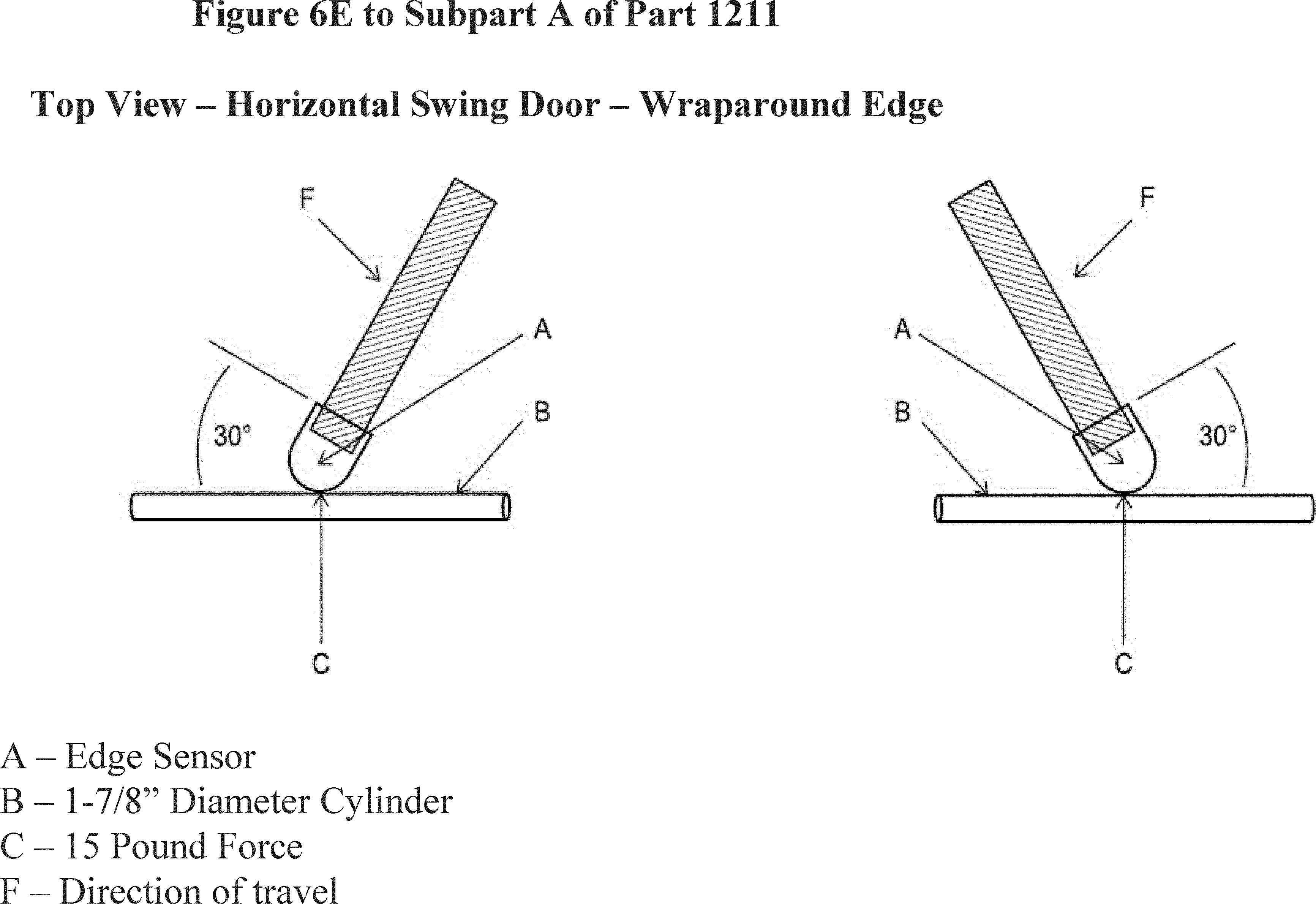
[83 FR 32571, July 13, 2018]
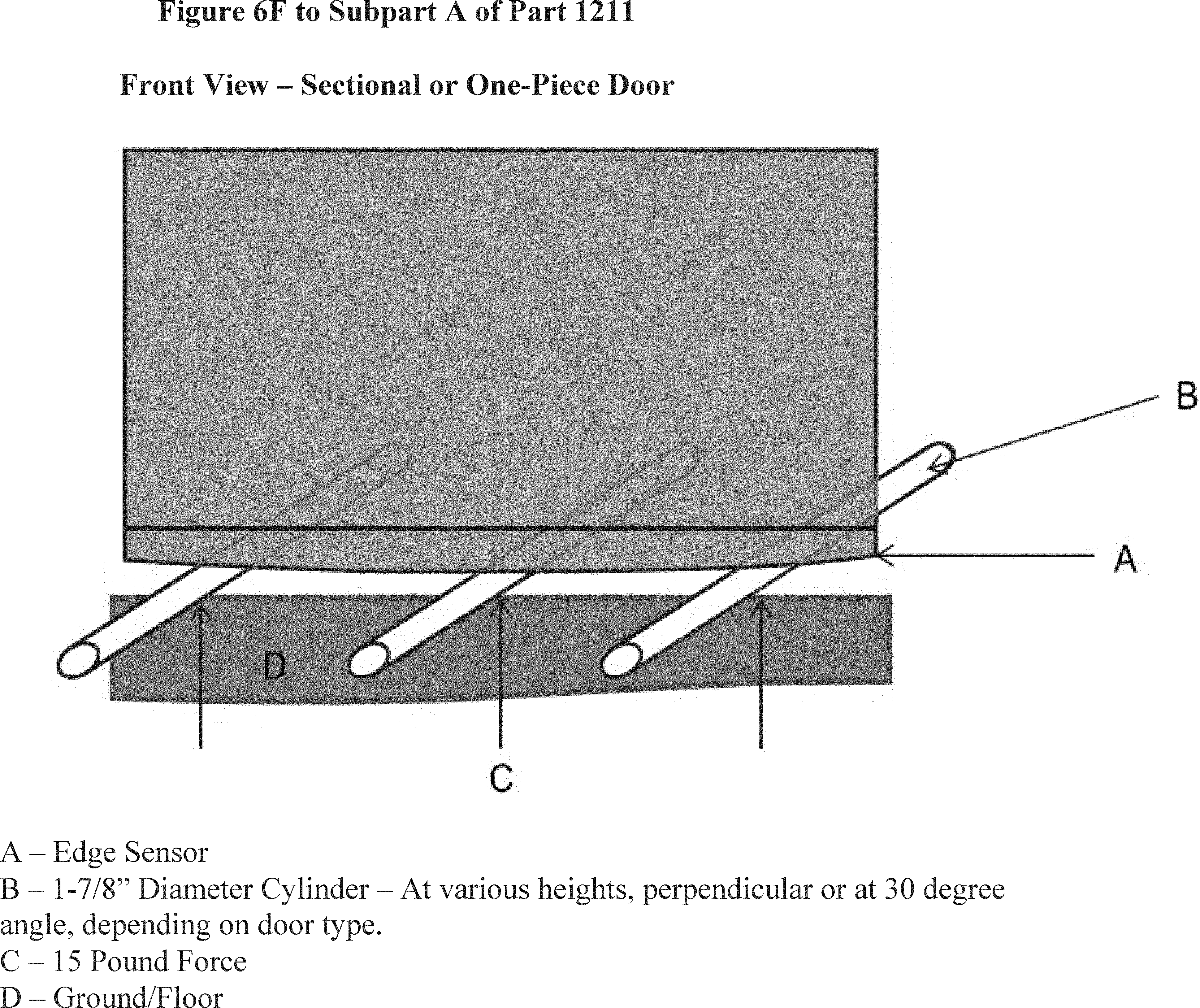
[83 FR 32571, July 13, 2018]
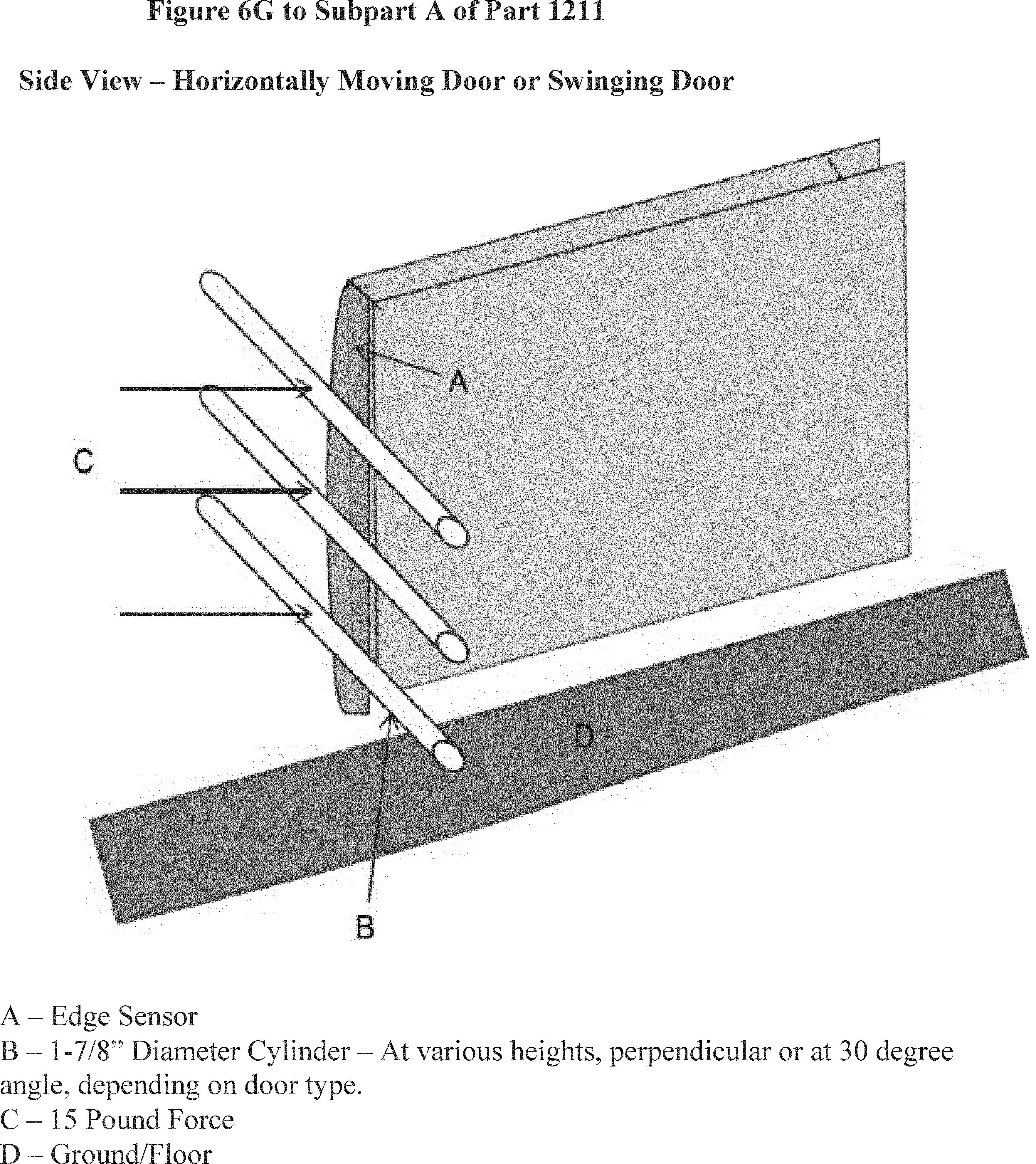
[83 FR 32571, July 13, 2018]
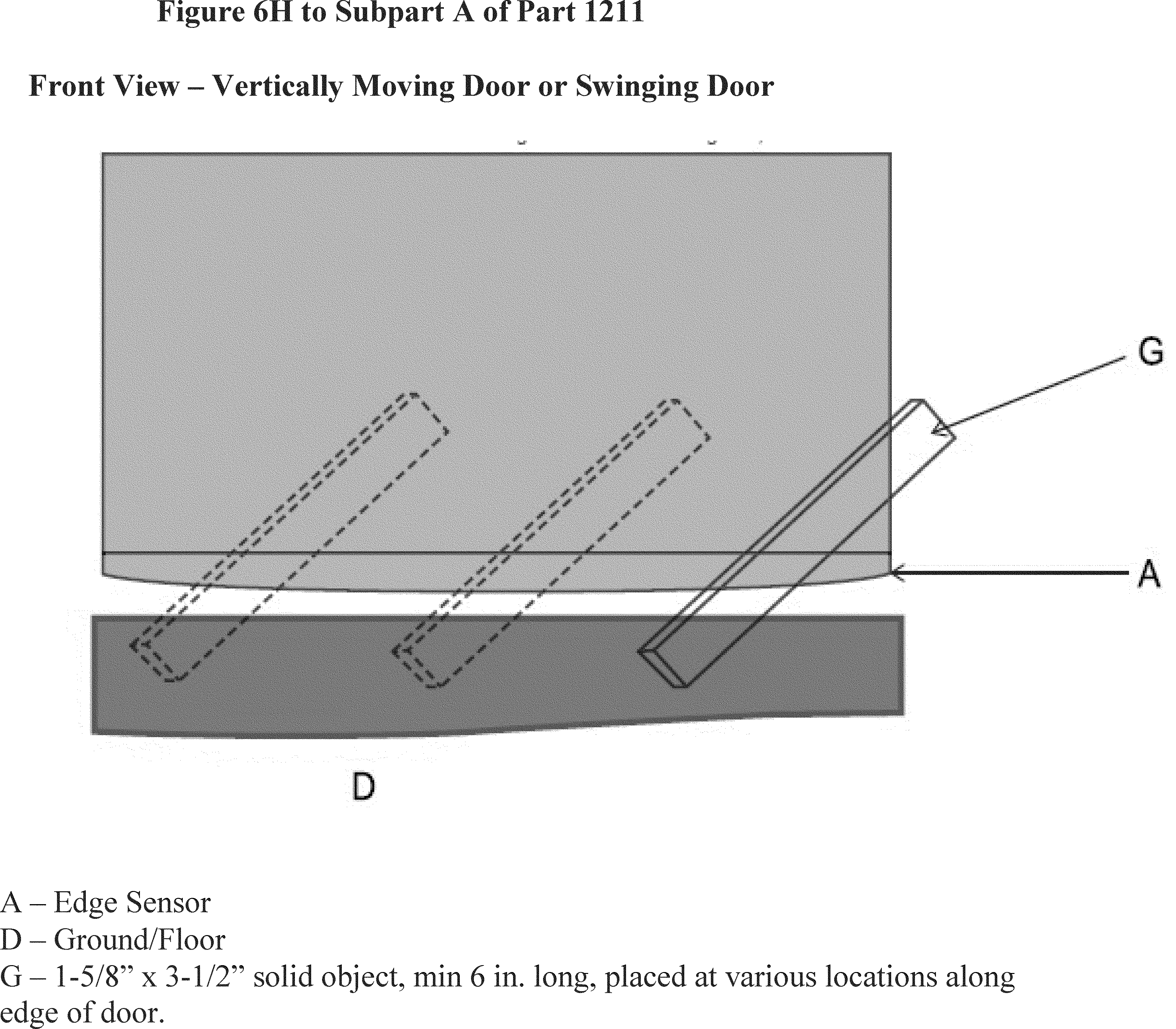
[83 FR 32571, July 13, 2018]

[83 FR 32571, July 13, 2018]
[81 FR 20238, Apr. 7, 2016]

[81 FR 20238, Apr. 7, 2016]

[81 FR 20238, Apr. 7, 2016]

[81 FR 20238, Apr. 7, 2016]
Table 1 to Subpart A of Part 1211—Physical Properties of Gasket-Accelerated Aging Test

[81 FR 20238, Apr. 7, 2016]
Subpart B - Certification
Source:
57 FR 60468, Dec. 21, 1992, unless otherwise noted.
§ 1211.20 Purpose, scope, and application.
(a) Purpose. Section 14(a) of the Consumer Product Safety Act, 15 U.S.C. 2063(a), requires every manufacturer (including importers) and private labeler of a product which is subject to a consumer product safety standard to issue a certificate that the product conforms to the applicable standard, and to base that certificate either on a test of each product or on a “reasonable testing program.” The purpose of this subpart is to establish requirements that manufacturers and importers of automatic residential garage door operators subject to the Safety Standard for Automatic Residential Garage Door Operators (16 CFR part 1211, subpart A), shall issue certificates of compliance in the form specified.
(b) Scope and application. The provisions of this subpart apply to all residential garage door operators which are subject to the requirements of the Safety Standard for Automatic Residential Garage Door Operators that take effect on January 1, 1993 or later.
§ 1211.21 Effective date.
Under the Consumer Product Safety Act, automatic residential garage door operators must certify that they comply with requirements of subpart A of this part. This certification requirement is currently in effect. The specific labeling requirement of the certification rule in this subpart will become effective for any automatic residential garage door operator manufactured on or after January 21, 1993.
§ 1211.22 Definitions.
The following definitions shall apply to this subpart:
(a) Private labeler means an owner of a brand or trademark which is used on an operator subject to the standard and which is not the brand or trademark of the manufacturer of the operator, provided the owner of the brand or trademark caused or authorized the operator to be so labeled and the brand or trademark of the manufacturer of such operator does not appear on the label.
(b) Production lot means a quantity of garage door operators from which certain operators are selected for testing prior to certifying the lot. All garage door operators in a lot must be essentially identical in those design, construction, and material features which relate to the ability of an operator to comply with the standard.
(c) Reasonable testing program means any test or series of tests which are identical or equivalent to, or more stringent than, the tests defined in the standard and which are performed on one or more garage door operators of the production lot for the purpose of determining whether there is reasonable assurance that the operators in that lot comply with the requirements of the standard.
§ 1211.23 Certification testing.
(a) General. Manufacturers and importers shall either test each individual garage door operator (or have it tested) or shall rely upon a reasonable testing program to demonstrate compliance with the requirements of the standard.
(b) Reasonable testing program. This paragraph provides guidance for establishing a reasonable testing program.
(1) A reasonable testing program for automatic residential garage door operators is one that provides reasonable assurance that the operators comply with the standard. Manufacturers and importers may define their own testing programs. Such reasonable testing programs may, at the option of manufacturers and importers, be conducted by an independent third party qualified to perform such testing programs.
(2) To conduct a reasonable testing program, the garage door operators should be divided into production lots. Sample operators from each production lot should be tested in accordance with the reasonable testing program so that there is a reasonable assurance that if the operators selected for testing meet the standard, all operators in the lot will meet the standard. Where there is a change in parts, suppliers of parts, or production methods that could affect the ability of the operator to comply with the requirements of the standard, the manufacturer should establish a new production lot for testing.
(3) The Commission will test for compliance with the standard by using the test procedures contained in the standard. However, a manufacturer's reasonable testing program may include either tests prescribed in the standard or any other reasonable test procedures.
(4) If the reasonable testing program shows that an operator does not comply with one or more requirements of the standard, no operator in the production lot can be certified as complying until all non-complying operators in the lot have been identified and destroyed or altered by repair, redesign, or use of a different material or components to the extent necessary to make them conform to the standard. The sale or offering for sale of garage door operators that do not comply with the standard is a prohibited act and a violation of section 19(a) of the CPSA (15 U.S.C. 2068(a)), regardless of whether the operator has been validly certified.
§ 1211.24 Product certification and labeling by manufacturers.
(a) Form of permanent label of certification. Manufacturers (including importers) shall issue certificates of compliance for automatic residential garage door operators manufactured after the effective date of the standard in the form of a permanent label which can reasonable be expected to remain on the operator during the entire period the operator is capable of being used. Such labeling shall be deemed to be a “certificate” of compliance as that term is used in section 14 of the CPSA, 15 U.S.C. 2063.
(b) Exception for UL listed operators. The certification labeling requirement of paragraph (a) of this section shall be satisfied by display of the Underwriters Laboratories, Inc. (UL) logo or listing mark, and compliance with the date marking requirements of UL Standard for Safety 325, on both the operator system and its container. Operators displaying the UL logo or listing mark and complying with the UL standard are exempt from the requirements of paragraphs (c) and (d) of this section.
(c) Contents of certification label. The certification labels required by this section shall clearly and legibly contain the following information:
(1) The statement “Meets CPSC ____ (insert 1993 or later date of applicable standard) garage door operator entrapment protection requirements.”
(2) An identification of the production lot.
(d) Placement of the label. The label required by this section must be affixed to the operator. If the label is not immediately visible to the ultimate purchaser of the garage door operator prior to purchase because of packaging or other marketing practices, a second label that states: “Meets CPSC ____ (insert 1993 or later date of applicable standard) garage door operator entrapment protection requirements,” along with the month or week and year of manufacture must appear on the container or, if the container is not visible, on the promotional material used with the sale of the operator.
§ 1211.25 Product certification and labeling by importers.
(a) General. The importer of any automatic residential garage door operator subject to the standard in subpart A of this part must issue the certificate of compliance required by section 14(a) of the CPSA and § 1211.24 of this subpart. If testing of each operator, or a reasonable testing program, meeting the requirements of this subpart has been performed by or for the foreign manufacturer of the product, the importer may rely in good faith on such tests to support the certificate of compliance provided the importer is a resident of the United States or has a resident agent in the United States and the records of such tests required by § 1211.31 of subpart C of this part are maintained in the United States.
(b) Responsibility of importer. If the importer relies on tests by the foreign manufacturer to support the certificate of compliance, the importer bears the responsibility for examining the records supplied by the manufacturer to determine that the records of such tests appear to comply with § 1211.31 of subpart C of this part.
Subpart C - Recordkeeping
Source:
57 FR 60468, Dec. 21, 1992, unless otherwise noted.
§ 1211.30 Effective date.
The recordkeeping requirements in this subpart shall become effective on January 21, 1993, and shall apply to automatic residential garage door operators manufactured on or after that date.
§ 1211.31 Recordkeeping requirements.
(a) General. Every person issuing certificates of compliance for automatic residential garage door operators subject to the standard set forth in subpart A of this part shall maintain written records which show that the certificates are based on a test of each operator or on a reasonable testing program. The records shall be maintained for a period of at least three years from the date of certification of each operator or the last operator in each production lot. These records shall be available to any designated officer or employee of the Commission upon request in accordance with section 16(b) of the CPSA, 15 U.S.C. 2065(b).
(b) Content of records. Records shall identify the operators tested and the production lot and describe the tests the operators were subjected to in sufficient detail so the tests may be replicated. Records shall also provide the results of the tests including the precise nature of any failures, and specific actions taken to address any failures.
(c) Format for records. The records required to be maintained by this section may be in any appropriate form or format that clearly provides the required information.
Subpart D - Incorporation by Reference
Source:
81 FR 20245, Apr. 7, 2016, unless otherwise noted.
§ 1211.40 Incorporation by reference.
(a) Certain material is incorporated by reference into this part with the approval of the Director of the Federal Register under 5 U.S.C. 552(a) and 1 CFR part 51. All approved material is available for inspection at Consumer Product Safety Commission, Office of the Secretary, 4330 East-West Highway, Bethesda, MD 20814, telephone 302-504-7923 and is available from the sources listed below. It is also available for inspection at the National Archives and Records Administration (NARA). For information on the availability of this material at NARA, call 202-741-6030 or go to http://www.archives.gov/federal_register/code_of_federal_regulations/ibr_locations.html.
(b) Door and Access Systems Manufacturers' Association, International (DASMA), 1300 Sumner Avenue, Cleveland, OH 44115-2851, Telephone: (216) 241-7333, http://www.dasma.com/dasma-pages/D-AS-standards.asp.
(1) ANSI/DASMA 102, Specifications for Sectional Doors, 2011 revision, dated May 19, 2011, into § 1211.6(c).
(2) [Reserved]
(c) National Fire Prevention Association (NFPA), 1 Batterymarch Park, Quincy, MA 02269-9101, Telephone: (800) 344-3555, http://www.nfpa.org/.
(1) NFPA 70, National Electrical Code, 2014 edition, effective August 21, 2013, into § 1211.2(c).
(2) [Reserved]
(d) UL, formerly Underwriters Laboratories, International, 151 Eastern Avenue, Bensenville, IL 60106, Telephone: 1-888-853-3503, http://ulstandards.ul.com/.
(1) UL 325, Standard for Safety: Door, Drapery, Gate, Louver, and Window Operators and Systems, SUPPLEMENT SA—(Normative)—UL 60335-1/CAN/CSA-C22.2 No. 60335-1 Based Requirements for the Evaluation of Electronic Circuits, Seventh Edition, May 19, 2017, into §§ 1211.4 and 1211.5.
(2) UL 746C, Standard for Safety: Polymeric Materials—Use in Electrical Equipment Evaluations, Sixth Edition, dated September 10, 2004, into §§ 1211.10(d) and (e) and 1211.12(c).
(3) UL 991, Standard for Safety: Tests for Safety-Related Controls Employing Solid-State Devices, Third Edition, dated October 22, 2004, into §§ 1211.4(c) and 1211.5(b)(3).
(4) UL 1998, Standard for Safety: Software in Programmable Components, Third Edition, December 18, 2013, into § 1211.8(f).
[81 FR 20245, Apr. 7, 2016, as amended at 83 FR 32579, July 13, 2018]