Subpart G - National Emission Standards for Organic Hazardous Air Pollutants From the Synthetic Organic Chemical Manufacturing Industry for Process Vents, Storage Vessels, Transfer Operations, and Wastewater
Source:
59 FR 19468, Apr. 22, 1994, unless otherwise noted.
§ 63.110 Applicability.
(a) This subpart applies to all process vents, storage vessels, transfer racks, wastewater streams, and in-process equipment subject to § 63.149 within a source subject to subpart F of this part.
(b) Overlap with other regulations for storage vessels.
(1) After the compliance dates specified in § 63.100 of subpart F of this part, a Group 1 or Group 2 storage vessel that is also subject to the provisions of 40 CFR part 60, subpart Kb is required to comply only with the provisions of this subpart.
(2) After the compliance dates specified in § 63.100 of subpart F of this part, a Group 1 storage vessel that is also subject to the provisions of 40 CFR part 61, subpart Y is required to comply only with the provisions of this subpart.
(3) After the compliance dates specified in § 63.100 of subpart F of this part, a Group 2 storage vessel that is also subject to the provisions of 40 CFR part 61, subpart Y is required to comply only with the provisions of 40 CFR part 61, subpart Y. The recordkeeping and reporting requirements of 40 CFR part 61, subpart Y will be accepted as compliance with the recordkeeping and reporting requirements of this subpart.
(c) Overlap with other regulations for transfer racks.
(1) After the compliance dates specified in § 63.100 of subpart F of this part, a Group 1 transfer rack that is also subject to the provisions of 40 CFR part 61, subpart BB is required to comply only with the provisions of this subpart.
(2) After the compliance dates specified in § 63.100 of subpart F of this part, a Group 2 transfer rack that is also subject to the provisions of 40 CFR part 61, subpart BB is required to comply with the provisions of either paragraph (c)(2)(i) or (c)(2)(ii) of this subpart.
(i) If the transfer rack is subject to the control requirements specified in § 61.302 of 40 CFR part 61, subpart BB, then the transfer rack is required to comply with the control requirements of § 61.302 of 40 CFR part 61, subpart BB. The owner or operator may elect to comply with either the associated testing, monitoring, reporting, and recordkeeping requirements of 40 CFR part 61, subpart BB or with the testing, monitoring, recordkeeping, and reporting requirements specified in this subpart for Group 1 transfer racks. The owner or operator shall indicate this decision in either the Notification of Compliance Status specified in § 63.152(b) of this subpart or in an operating permit application or amendment.
(ii) If the transfer rack is subject only to reporting and recordkeeping requirements under 40 CFR part 61, subpart BB, then the transfer rack is required to comply only with the reporting and recordkeeping requirements specified in this subpart for Group 2 transfer racks and is exempt from the reporting and recordkeeping requirements in 40 CFR part 61, subpart BB.
(d) Overlap with other regulations for process vents.
(1) After the compliance dates specified in § 63.100 of subpart F of this part, a Group 1 process vent that is also subject to the provisions of 40 CFR part 60, subpart III is required to comply only with the provisions of this subpart.
(2) After the compliance dates specified in § 63.100 of subpart F of this part, the owner or operator of a Group 2 process vent that is also subject to the provisions of 40 CFR part 60, subpart III shall determine requirements according to paragraphs (d)(2)(i) and (d)(2)(ii) of this section.
(i) If the Group 2 process vent has a TRE value less than 1 as determined by the procedures in 40 CFR part 60, subpart III, the process vent is required to comply with the provisions in paragraphs (d)(2)(i)(A) through (d)(2)(i)(C) of this section.
(A) The provisions in both this subpart and in 40 CFR part 60, subpart III for applicability determination and the associated recordkeeping and reporting;
(B) The provisions in both this subpart and in 40 CFR part 60, subpart III for process changes and recalculation of the TRE index value and the associated recordkeeping and reporting; and
(C) The control requirements in § 60.612 of 40 CFR part 60, subpart III. The owner or operator may elect to comply with either the associated testing, monitoring, reporting, and recordkeeping requirements of 40 CFR part 60, subpart III or with the testing, monitoring, reporting, and recordkeeping requirements specified in this subpart for Group 1 process vents. The owner or operator shall indicate this decision in either the Notification of Compliance Status specified in § 63.152(b) of this subpart or in an operating permit application or amendment.
(ii) If the Group 2 process vent has a TRE value greater than or equal to 1 as determined by the procedures in 40 CFR part 60, subpart III, the process vent is required to comply only with the provisions specified in paragraphs (d)(2)(ii)(A) through (d)(2)(ii)(D) of this section.
(A) The provisions in both this subpart and in 40 CFR part 60, subpart III for applicability determination and the associated recordkeeping and reporting;
(B) The provisions in both this subpart and in 40 CFR part 60, subpart III for process changes and recalculation of the TRE index value and the associated recordkeeping and reporting;
(C) If the provisions of both this subpart and 40 CFR part 60, subpart III require continuous monitoring of recovery device operating parameters, the process vent is required to comply only with the provisions that are specified in this subpart for continuous monitoring of recovery device operating parameters and the associated testing, reporting, and recordkeeping.
(D) If only the provisions of 40 CFR part 60, subpart III require continuous monitoring of recovery device operating parameters, the process vent is required to comply only with the provisions that are specified in 40 CFR part 60, subpart III for continuous monitoring of recovery device operating parameters and the associated testing, reporting, and recordkeeping.
(3) After the compliance dates specified in 63.100 of subpart F of this part, if an owner or operator of a process vent subject to this subpart that is also subject to the provisions of 40 CFR part 60, subpart III elects to control the process vent to the levels required in § 63.113 (a)(1) or (a)(2) of this subpart without calculating the TRE index value for the vent according to the procedures specified in § 63.115(d) of this subpart then the owner or operator shall comply with the testing, monitoring, reporting, and recordkeeping provisions of this subpart and shall be exempt from the testing, monitoring, reporting, and recordkeeping provisions of 40 CFR part 60, subpart III.
(4) After the compliance dates specified in § 63.100 of subpart F of this part, a Group 1 process vent that is also subject to the provisions of 40 CFR part 60, subpart NNN is required to comply only with the provisions of this subpart.
(5) After the compliance dates specified in § 63.100 of subpart F of this part, the owner or operator of a Group 2 process vent that is also subject to the provisions of 40 CFR part 60, subpart NNN shall determine requirements according to paragraphs (d)(5)(i) and (d)(5)(ii) of this section.
(i) If the Group 2 process vent has a TRE value less than 1 as determined by the procedures in 40 CFR part 60, subpart NNN, the process vent is required to comply with the provisions in paragraphs (d)(5)(i)(A) through (d)(5)(i)(C) of this section.
(A) The provisions in both this subpart and in 40 CFR part 60, subpart NNN for applicability determination and the associated recordkeeping and reporting;
(B) The provisions in both this subpart and in 40 CFR part 60, subpart NNN for process changes and recalculation of the TRE index value and the associated recordkeeping and reporting; and
(C) The control requirements in § 60.662 of 40 CFR part 60, subpart NNN. The owner or operator may elect to comply with either the associated testing, monitoring, reporting, and recordkeeping requirements of 40 CFR part 60, subpart NNN or with the testing, monitoring, reporting, and recordkeeping requirements specified in this subpart for Group 1 process vents. The owner or operator shall indicate this decision in either the Notification of Compliance Status specified in § 63.152(b) of this subpart or in an operating permit application or amendment.
(ii) If the Group 2 process vent has a TRE value greater than or equal to 1 as determined by the procedures in 40 CFR part 60, subpart NNN, the process vent is required to comply only with the provisions specified in paragraphs (d)(5)(ii)(A) through (d)(5)(ii)(D) of this section.
(A) The provisions in both this subpart and in 40 CFR part 60, subpart NNN for applicability determination and the associated recordkeeping and reporting;
(B) The provisions in both this subpart and in 40 CFR part 60, subpart NNN for process changes and recalculation of the TRE index value and the associated recordkeeping and reporting;
(C) If the provisions of both this subpart and 40 CFR part 60, subpart NNN require continuous monitoring of recovery device operating parameters, the process vent is required to comply only with the provisions that are specified in this subpart for continuous monitoring of recovery device operating parameters and the associated testing, reporting, and recordkeeping.
(D) If only the provisions of 40 CFR part 60, subpart NNN require continuous monitoring of recovery device operating parameters, the process vent is required to comply only with the provisions that are specified in 40 CFR part 60, subpart NNN for continuous monitoring of recovery device operating parameters and the associated testing, reporting, and recordkeeping.
(6) After the compliance dates specified in § 63.100 of subpart F of this part, if an owner or operator of a process vent subject to this subpart that is also subject to the provisions of 40 CFR part 60, subpart NNN elects to control the process vent to the levels required in § 63.113(a)(1) or (a)(2) of this subpart without calculating the TRE index value for the vent according to the procedures specified in § 63.115(d) of this subpart then the owner or operator shall comply with the testing, monitoring, reporting, and recordkeeping provisions of this subpart and shall be exempt from the testing, monitoring, reporting, and recordkeeping provisions of 40 CFR part 60, subpart NNN.
(7) After the compliance dates specified in § 63.100 of subpart F of this part, a Group 1 process vent that is also subject to the provisions of 40 CFR part 60, subpart RRR is required to comply only with the provisions of this subpart.
(8) After the compliance dates specified in § 63.100 of subpart F of this part, the owner or operator of a Group 2 process vent that is also subject to the provisions of 40 CFR part 60, subpart RRR shall determine requirements according to paragraphs (d)(8)(i) and (d)(8)(ii) of this section.
(i) If the Group 2 process vent has a TRE value less than 1 as determined by the procedures in 40 CFR part 60, subpart RRR, the process vent is required to comply with the provisions in paragraphs (d)(8)(i)(A) through (d)(8)(i)(C) of this section.
(A) The provisions in both this subpart and in 40 CFR part 60, subpart RRR for applicability determination and the associated recordkeeping and reporting;
(B) The provisions in both this subpart and in 40 CFR part 60, subpart RRR for process changes and recalculation of the TRE index value and the associated recordkeeping and reporting; and
(C) The control requirements in § 60.702 of 40 CFR part 60, subpart RRR. The owner or operator may elect to comply with either the associated testing, monitoring, reporting, and recordkeeping requirements of 40 CFR part 60, subpart RRR or with the testing, monitoring, reporting, and recordkeeping requirements specified in this subpart for Group 1 process vents. The owner or operator shall indicate this decision in either the Notification of Compliance Status specified in § 63.152(b) of this subpart or in an operating permit application or amendment.
(ii) If the Group 2 process vent has a TRE value greater than or equal to 1 as determined by the procedures in 40 CFR part 60, subpart RRR, the process vent is required to comply only with the provisions specified in paragraphs (d)(8)(ii)(A) through (d)(8)(ii)(D) of this section.
(A) The provisions in both this subpart and in 40 CFR part 60, subpart RRR for applicability determination and the associated recordkeeping and reporting;
(B) The provisions in both this subpart and in 40 CFR part 60, subpart RRR for process changes and recalculation of the TRE index value and the associated recordkeeping and reporting;
(C) If the provisions of both this subpart and 40 CFR part 60, subpart RRR require continuous monitoring of recovery device operating parameters, the process vent is required to comply only with the provisions that are specified in this subpart for continuous monitoring of recovery device operating parameters and the associated testing, reporting, and recordkeeping.
(D) If only the provisions of 40 CFR part 60, subpart RRR require continuous monitoring of recovery device operating parameters, the process vent is required to comply only with the provisions that are specified in 40 CFR part 60, subpart RRR for continuous monitoring of recovery device operating parameters and the associated testing, reporting, and recordkeeping.
(9) After the compliance dates specified in § 63.100 of subpart F of this part, if an owner or operator of a process vent subject to this subpart that is also subject to the provisions of 40 CFR part 60, subpart RRR elects to control the process vent to the levels required in § 63.113(a)(1) or (a)(2) of this subpart without calculating the TRE index value for the vent according to the procedures specified in § 63.115(d) of this subpart then the owner or operator shall comply with the testing, monitoring, reporting, and recordkeeping provisions of this subpart and shall be exempt from the testing, monitoring, reporting, and recordkeeping provisions of 40 CFR part 60, subpart RRR.
(10) As an alternative to the requirements of paragraphs (d)(2), (d)(3), (d)(5), (d)(6), (d)(8), and/or (d)(9) of this section as applicable, if a chemical manufacturing process unit has equipment subject to the provisions of this subpart and equipment subject to the provisions of 40 CFR part 60, subpart III, NNN, or RRR, the owner or operator may elect to apply this subpart to all such equipment in the chemical manufacturing process unit. If the owner or operator elects this method of compliance, all total organic compounds minus methane and ethane, in such equipment shall be considered for purposes of applicability and compliance with this subpart, as if they were organic hazardous air pollutants. Compliance with the provisions of this subpart, in the manner described in this paragraph, shall be deemed to constitute compliance with 40 CFR part 60, subpart III, NNN, or RRR, as applicable.
(e) Overlap with other regulations for wastewater.
(1) After the compliance dates specified in § 63.100 of subpart F of this part, the owner or operator of a Group 1 or Group 2 wastewater stream that is also subject to the provisions of 40 CFR part 61, subpart FF is required to comply with the provisions of both this subpart and 40 CFR part 61, subpart FF. Alternatively, the owner or operator may elect to comply with the provisions of paragraphs (e)(1)(i) and (e)(1)(ii) of this section, which shall constitute compliance with the provisions of 40 CFR part 61, subpart FF.
(i) Comply with the provisions of this subpart; and
(ii) For any Group 2 wastewater stream or organic stream whose benzene emissions are subject to control through the use of one or more treatment processes or waste management units under the provisions of 40 CFR part 61, subpart FF on or after December 31, 1992, comply with the requirements of this subpart for Group 1 wastewater streams.
(2) After the compliance dates specified in § 63.100 of subpart F of this part, the owner or operator of any Group 1 or Group 2 wastewater stream that is also subject to provisions in 40 CFR parts 260 through 272 shall comply with the requirements of either paragraph (e)(2)(i) or (e)(2)(ii) of this section.
(i) For each Group 1 or Group 2 wastewater stream, the owner or operator shall comply with the more stringent control requirements (e.g., waste management units, numerical treatment standards, etc.) and the more stringent testing, monitoring, recordkeeping, and reporting requirements that overlap between the provisions of this subpart and the provisions of 40 CFR parts 260 through 272. The owner or operator shall keep a record of the information used to determine which requirements were the most stringent and shall submit this information if requested by the Administrator; or
(ii) The owner or operator shall submit, no later than four months before the applicable compliance date specified in § 63.100 of subpart F of this part, a request for a case-by-case determination of requirements. The request shall include the information specified in paragraphs (e)(2)(ii)(A) and (e)(2)(ii)(B) of this section.
(A) Identification of the wastewater streams that are subject to this subpart and to provisions in 40 CFR parts 260 through 272, determination of the Group 1/Group 2 status of those streams, determination of whether or not those streams are listed or exhibit a characteristic as specified in 40 CFR part 261, and determination of whether the waste management unit is subject to permitting under 40 CFR part 270.
(B) Identification of the specific control requirements (e.g., waste management units, numerical treatment standards, etc.) and testing, monitoring, recordkeeping, and reporting requirements that overlap between the provisions of this subpart and the provisions of 40 CFR parts 260 through 272.
(f) Overlap with the Vinyl Chloride NESHAP.
(1) After the compliance dates specified in § 63.100 of subpart F of this part, the owner or operator of any Group 1 process vent that is also subject to the provisions of 40 CFR part 61, subpart F shall comply only with the provisions of this subpart.
(2) After the compliance dates specified in § 63.100 of subpart F of this part, the owner or operator of any Group 2 process vent that is also subject to the provisions of 40 CFR part 61, subpart F shall comply with the provisions specified in either paragraph (f)(2)(i) or (f)(2)(ii) of this subpart.
(i) If the process vent is already controlled by a combustion device meeting the requirements of 40 CFR part 61, subpart F, then the owner or operator shall comply with either the associated testing, monitoring, reporting, and recordkeeping provisions for Group 1 process vents in this subpart or the testing, monitoring, reporting, and recordkeeping provisions of 40 CFR part 61, subpart F. The owner or operator shall indicate this decision in either the Notification of Compliance Status specified in § 63.152(b) of this subpart or in an operating permit application or amendment.
(ii) If the process vent is not already controlled by a combustion device, then the owner or operator shall comply with the provisions of both this subpart and 40 CFR part 61, subpart F.
(3) After the compliance dates specified in § 63.100 of subpart F of this part, if an owner or operator of a process vent subject to this subpart that is also subject to the provisions of 40 CFR part 61, subpart F elects to control the process vent to the levels required in § 63.113(a)(1) or (a)(2) of this subpart without calculating the TRE index value for the vent according to the procedures specified in § 63.115(d) of this subpart then the owner or operator shall comply with the testing, monitoring, reporting, and recordkeeping provisions of this subpart and shall be exempt from the testing, monitoring, reporting, and recordkeeping provisions of 40 CFR part 61, subpart F.
(4) After the compliance dates specified in § 63.100 of subpart F of this part, the owner or operator of a Group 1 or Group 2 wastewater stream that is also subject to the provisions of 40 CFR part 61, subpart F shall comply with the provisions of either paragraph (f)(4)(i) or (f)(4)(ii) of this section.
(i) The owner or operator shall comply with the provisions of both this subpart and 40 CFR part 61, subpart F or
(ii) The owner or operator may submit, no later than four months before the applicable compliance date specified in § 63.100 of subpart F of this part, information demonstrating how compliance with 40 CFR Part 61, subpart F, will also ensure compliance with this subpart. The information shall include a description of the testing, monitoring, reporting, and recordkeeping that will be performed.
(g) Rules stayed for reconsideration. Notwithstanding any other provision of this subpart, the effectiveness of subpart G is stayed from October 24, 1994, to April 24, 1995, only as applied to those sources for which the owner or operator makes a representation in writing to the Administrator that the resolution of the area source definition issues could have an effect on the compliance status of the source with respect to subpart G.
(h) Overlap with other regulations for monitoring, recordkeeping, or reporting with respect to combustion devices, recovery devices, or recapture devices. After the compliance dates specified in § 63.100 of subpart F of this part, if any combustion device, recovery device, or recapture device subject to this subpart is also subject to monitoring, recordkeeping, and reporting requirements in 40 CFR part 264, subpart AA or CC, or is subject to monitoring and recordkeeping requirements in 40 CFR part 265, subpart AA or CC and the owner or operator complies with the periodic reporting requirements under 40 CFR part 264, subpart AA or CC that would apply to the device if the facility had final-permitted status, the owner or operator may elect to comply either with the monitoring, recordkeeping, and reporting requirements of this subpart, or with the monitoring, recordkeeping, and reporting requirements in 40 CFR parts 264 and/or 265, as described in this paragraph, which shall constitute compliance with the monitoring, recordkeeping, and reporting requirements of this subpart. The owner or operator shall identify which option has been selected in the Notification of Compliance Status required by § 63.152(b).
(i) Alternative means of compliance —
(1) Option to comply with part 65. Owners or operators of CMPU that are subject to § 63.100 may choose to comply with the provisions of 40 CFR part 65 for all Group 1 and Group 2 process vents, Group 1 storage vessels, Group 1 transfer operations, and equipment that are subject to § 63.100, that are part of the CMPU. Other provisions applying to owners or operators who choose to comply with 40 CFR part 65 are provided in 40 CFR 65.1. Group 1 and Group 2 wastewater streams, Group 2 transfer operations, Group 2 storage vessels, and in-process streams are not eligible to comply with 40 CFR part 65 and must continue to comply with the requirements of this subpart and subpart F of this part.
(i) For Group 1 and Group 2 process vents, 40 CFR part 65, subpart D, satisfies the requirements of §§ 63.102, 63.103, 63.112 through 63.118, 63.148, 63.151, and 63.152.
(ii) For Group 1 storage vessels, 40 CFR part 65, subpart C, satisfies the requirements of §§ 63.102, 63.103, 63.112, 63.119 through 63.123, 63.148, 63.151, and 63.152.
(iii) For Group 1 transfer racks, 40 CFR part 65, subpart E, satisfies the requirements of §§ 63.102, 63.103, 63.112, 63.126 through 63.130, 63.148, 63.151, and 63.152.
(iv) For equipment, comply with § 65.160(g).
(2) Part 63, subpart A. Owners or operators who choose to comply with 40 CFR part 65 must also comply with the applicable general provisions of this part 63 listed in table 1A of this subpart. All sections and paragraphs of subpart A of this part that are not mentioned in table 1A of this subpart do not apply to owners or operators who choose to comply with 40 CFR part 65, except that provisions required to be met prior to implementing 40 CFR part 65 still apply. Owners and operators who choose to comply with a subpart of 40 CFR part 65 must comply with 40 CFR part 65, subpart A.
[59 FR 19468, Apr. 22, 1994, as amended at 59 FR 53360, Oct. 24, 1994; 60 FR 5321, Jan. 27, 1995; 61 FR 64575, Dec. 5, 1996; 62 FR 2742, Jan. 17, 1997; 65 FR 78284, Dec. 14, 2000; 66 FR 6929, Jan. 22, 2001]
§ 63.111 Definitions.
All terms used in this subpart shall have the meaning given them in the Act, in subpart F of this part, and in this section, as follows.
Air oxidation reactor means a device or vessel in which air, or a combination of air and oxygen, is used as an oxygen source in combination with one or more organic reactants to produce one or more organic compounds. Air oxidation reactor includes the product separator and any associated vacuum pump or steam jet.
Annual average concentration, as used in the wastewater provisions, means the flow-weighted annual average concentration, as determined according to the procedures specified in § 63.144(b) of this subpart.
Annual average flow rate, as used in the wastewater provisions, means the annual average flow rate, as determined according to the procedures specified in § 63.144(c).
Automated monitoring and recording system means any means of measuring values of monitored parameters and creating a hard copy or computer record of the measured values that does not require manual reading of monitoring instruments and manual transcription of data values. Automated monitoring and recording systems include, but are not limited to, computerized systems and strip charts.
Batch operation means a noncontinuous operation in which a discrete quantity or batch of feed is charged into a unit operation within a chemical manufacturing process unit and distilled or reacted at one time. Batch operation includes noncontinuous operations in which the equipment is fed intermittently or discontinuously. Addition of raw material and withdrawal of product do not occur simultaneously in a batch operation. After each batch operation, the equipment is generally emptied before a fresh batch is started.
Boiler means any enclosed combustion device that extracts useful energy in the form of steam and is not an incinerator. Boiler also means any industrial furnace as defined in 40 CFR 260.10.
By compound means by individual stream components, not carbon equivalents.
Car-seal means a seal that is placed on a device that is used to change the position of a valve (e.g., from opened to closed) in such a way that the position of the valve cannot be changed without breaking the seal.
Chemical manufacturing process unit means the equipment assembled and connected by pipes or ducts to process raw materials and to manufacture an intended product. A chemical manufacturing process unit consists of more than one unit operation. For the purpose of this subpart, chemical manufacturing process unit includes air oxidation reactors and their associated product separators and recovery devices; reactors and their associated product separators and recovery devices; distillation units and their associated distillate receivers and recovery devices; associated unit operations; associated recovery devices; and any feed, intermediate and product storage vessels, product transfer racks, and connected ducts and piping. A chemical manufacturing process unit includes pumps, compressors, agitators, pressure relief devices, sampling connection systems, open-ended valves or lines, valves, connectors, instrumentation systems, and control devices or systems. A chemical manufacturing process unit is identified by its primary product.
Closed biological treatment process means a tank or surface impoundment where biological treatment occurs and air emissions from the treatment process are routed to either a control device by means of a closed vent system or to a fuel gas system by means of hard-piping. The tank or surface impoundment has a fixed roof, as defined in § 63.111 of this subpart, or a floating flexible membrane cover that meets the requirements specified in § 63.134 of this subpart.
Closed-vent system means a system that is not open to the atmosphere and is composed of piping, ductwork, connections, and, if necessary, flow inducing devices that transport gas or vapor from an emission point to a control device.
Combustion device means an individual unit of equipment, such as a flare, incinerator, process heater, or boiler, used for the combustion of organic hazardous air pollutant emissions.
Container, as used in the wastewater provisions, means any portable waste management unit that has a capacity greater than or equal to 0.1 m3 in which a material is stored, transported, treated, or otherwise handled. Examples of containers are drums, barrels, tank trucks, barges, dumpsters, tank cars, dump trucks, and ships.
Continuous record means documentation, either in hard copy or computer readable form, of data values measured at least once every 15 minutes and recorded at the frequency specified in § 63.152(f) or § 63.152(g) of this subpart.
Continuous recorder means a data recording device that either records an instantaneous data value at least once every 15 minutes or records 15-minute or more frequent block average values.
Continuous seal means a seal that forms a continuous closure that completely covers the space between the wall of the storage vessel and the edge of the floating roof. A continuous seal may be a vapor-mounted, liquid-mounted, or metallic shoe seal. A continuous seal may be constructed of fastened segments so as to form a continuous seal.
Continuous vapor processing system means a vapor processing system that treats total organic compound vapors collected from tank trucks or railcars on a demand basis without intermediate accumulation in a vapor holder.
Control device means any combustion device, recovery device, or recapture device. Such equipment includes, but is not limited to, absorbers, carbon adsorbers, condensers, incinerators, flares, boilers, and process heaters. For process vents, recapture devices are considered control devices but recovery devices are not considered control devices, and for a steam stripper, a primary condenser is not considered a control device.
Cover, as used in the wastewater provisions, means a device or system which is placed on or over a waste management unit containing wastewater or residuals so that the entire surface area is enclosed to minimize air emissions. A cover may have openings necessary for operation, inspection, and maintenance of the waste management unit such as access hatches, sampling ports, and gauge wells provided that each opening is closed when not in use. Examples of covers include a fixed roof installed on a wastewater tank, a lid installed on a container, and an air-supported enclosure installed over a waste management unit.
Distillate receiver means overhead receivers, overhead accumulators, reflux drums, and condenser(s) including ejector-condenser(s) associated with a distillation unit.
Distillation unit means a device or vessel in which one or more feed streams are separated into two or more exit streams, each exit stream having component concentrations different from those in the feed stream(s). The separation is achieved by the redistribution of the components between the liquid and the vapor phases by vaporization and condensation as they approach equilibrium within the distillation unit. Distillation unit includes the distillate receiver, reboiler, and any associated vacuum pump or steam jet.
Duct work means a conveyance system such as those commonly used for heating and ventilation systems. It is often made of sheet metal and often has sections connected by screws or crimping. Hard-piping is not ductwork.
Enhanced biological treatment system or enhanced biological treatment process means an aerated, thoroughly mixed treatment unit(s) that contains biomass suspended in water followed by a clarifier that removes biomass from the treated water and recycles recovered biomass to the aeration unit. The mixed liquor volatile suspended solids (biomass) is greater than 1 kilogram per cubic meter throughout each aeration unit. The biomass is suspended and aerated in the water of the aeration unit(s) by either submerged air flow or mechanical agitation. A thoroughly mixed treatment unit is a unit that is designed and operated to approach or achieve uniform biomass distribution and organic compound concentration throughout the aeration unit by quickly dispersing the recycled biomass and the wastewater entering the unit.
External floating roof means a pontoon-type or double-deck-type cover that rests on the liquid surface in a storage vessel or waste management unit with no fixed roof.
Fill or filling means the introduction of organic hazardous air pollutant into a storage vessel or the introduction of a wastewater stream or residual into a waste management unit, but not necessarily to complete capacity.
First attempt at repair means to take action for the purpose of stopping or reducing leakage of organic material to the atmosphere.
Fixed roof means a cover that is mounted on a waste management unit or storage vessel in a stationary manner and that does not move with fluctuations in liquid level.
Flame zone means the portion of the combustion chamber in a boiler or process heater occupied by the flame envelope.
Floating roof means a cover consisting of a double deck, pontoon single deck, internal floating cover or covered floating roof, which rests upon and is supported by the liquid being contained, and is equipped with a closure seal or seals to close the space between the roof edge and waste management unit or storage vessel wall.
Flow indicator means a device which indicates whether gas flow is, or whether the valve position would allow gas flow to be, present in a line.
Fuel gas means gases that are combusted to derive useful work or heat.
Fuel gas system means the offsite and onsite piping and control system that gathers gaseous stream(s) generated by onsite operations, may blend them with other sources of gas, and transports the gaseous stream for use as fuel gas in combustion devices, or in-process combustion equipment such as furnaces and gas turbines, either singly or in combination.
Group 1 process vent means a process vent for which the vent stream flow rate is greater than or equal to 0.005 standard cubic meter per minute, the total organic HAP concentration is greater than or equal to 50 parts per million by volume, and the total resource effectiveness index value, calculated according to § 63.115, is less than or equal to 1.0.
Group 2 process vent means a process vent for which the vent stream flow rate is less than 0.005 standard cubic meter per minute, the total organic HAP concentration is less than 50 parts per million by volume or the total resource effectiveness index value, calculated according to § 63.115, is greater than 1.0.
Group 1 storage vessel means a storage vessel that meets the criteria for design storage capacity and stored-liquid maximum true vapor pressure specified in table 5 of this subpart for storage vessels at existing sources, and in table 6 of this subpart for storage vessels at new sources.
Group 2 storage vessel means a storage vessel that does not meet the definition of a Group 1 storage vessel.
Group 1 transfer rack means a transfer rack that annually loads greater than or equal to 0.65 million liter of liquid products that contain organic hazardous air pollutants with a rack weighted average vapor pressure greater than or equal to 10.3 kilopascals.
Group 2 transfer rack means a transfer rack that does not meet the definition of Group 1 transfer rack.
Group 1 wastewater stream means a wastewater stream consisting of process wastewater as defined in § 63.101 of subpart F at an existing or new source that meets the criteria for Group 1 status in § 63.132(c) of this subpart for Table 9 compounds and/or a wastewater stream consisting of process wastewater at a new source that meets the criteria for Group 1 status in § 63.132(d) of this subpart for Table 8 compounds.
Group 2 wastewater stream means any process wastewater stream that does not meet the definition of a Group 1 wastewater stream.
Halogenated vent stream or halogenated stream means a vent stream from a process vent or transfer operation determined to have a mass emission rate of halogen atoms contained in organic compounds of 0.45 kilograms per hour or greater determined by the procedures presented in § 63.115(d)(2)(v) of this subpart.
Halogens and hydrogen halides means hydrogen chloride (HCl), chlorine (Cl2), hydrogen bromide (HBr), bromine (Br2), and hydrogen fluoride (HF).
Hard-piping means pipe or tubing that is manufactured and properly installed using good engineering judgment and standards such as American National Standards Institute (ANSI) B31-3.
Incinerator means an enclosed combustion device that is used for destroying organic compounds. Auxiliary fuel may be used to heat waste gas to combustion temperatures. Any energy recovery section present is not physically formed into one manufactured or assembled unit with the combustion section; rather, the energy recovery section is a separate section following the combustion section and the two are joined by ducts or connections carrying flue gas. The above energy recovery section limitation does not apply to an energy recovery section used solely to preheat the incoming vent stream or combustion air.
Individual drain system means the stationary system used to convey wastewater streams or residuals to a waste management unit or to discharge or disposal. The term includes hard-piping, all process drains and junction boxes, together with their associated sewer lines and other junction boxes, manholes, sumps, and lift stations, conveying wastewater streams or residuals. A segregated stormwater sewer system, which is a drain and collection system designed and operated for the sole purpose of collecting rainfall runoff at a facility, and which is segregated from all other individual drain systems, is excluded from this definition.
Intermittent vapor processing system means a vapor processing system that employs an intermediate vapor holder to accumulate total organic compound vapors collected from tank trucks or railcars, and treats the accumulated vapors only during automatically controlled cycles.
Internal floating roof means a cover that rests or floats on the liquid surface (but not necessarily in complete contact with it) inside a storage vessel or waste management unit that has a permanently affixed roof.
Junction box means a manhole or access point to a wastewater sewer line or a lift station.
Liquid-mounted seal means a foam- or liquid-filled seal mounted in contact with the liquid between the wall of the storage vessel or waste management unit and the floating roof. The seal is mounted continuously around the circumference of the vessel or unit.
Loading cycle means the time period from the beginning of filling a tank truck or railcar until flow to the control device ceases, as measured by the flow indicator.
Loading rack means a single system used to fill tank trucks and railcars at a single geographic site. Loading equipment and operations that are physically separate (i.e., do not share common piping, valves, and other equipment) are considered to be separate loading racks.
Maximum true vapor pressure means the equilibrium partial pressure exerted by the total organic HAP's in the stored or transferred liquid at the temperature equal to the highest calendar-month average of the liquid storage or transfer temperature for liquids stored or transferred above or below the ambient temperature or at the local maximum monthly average temperature as reported by the National Weather Service for liquids stored or transferred at the ambient temperature, as determined:
(1) In accordance with methods described in American Petroleum Institute Publication 2517, Evaporative Loss From External Floating-Roof Tanks (incorporated by reference as specified in § 63.14 of subpart A of this part); or
(2) As obtained from standard reference texts; or
(3) As determined by the American Society for Testing and Materials Method D2879-83 or 96 (incorporated by reference as specified in § 63.14 of subpart A of this part); or
(4) Any other method approved by the Administrator.
Metallic shoe seal or mechanical shoe seal means metal sheets that are held vertically against the wall of the storage vessel by springs, weighted levers, or other mechanisms and connected to the floating roof by braces or other means. A flexible coated fabric (envelope) spans the annular space between the metal sheet and the floating roof.
Non-automated monitoring and recording system means manual reading of values measured by monitoring instruments and manual transcription of those values to create a record. Non-automated systems do not include strip charts.
Oil-water separator or organic-water separator means a waste management unit, generally a tank used to separate oil or organics from water. An oil-water or organic-water separator consists of not only the separation unit but also the forebay and other separator basins, skimmers, weirs, grit chambers, sludge hoppers, and bar screens that are located directly after the individual drain system and prior to additional treatment units such as an air flotation unit, clarifier, or biological treatment unit. Examples of an oil-water or organic-water separator include, but are not limited to, an American Petroleum Institute separator, parallel-plate interceptor, and corrugated-plate interceptor with the associated ancillary equipment.
Open biological treatment process means a biological treatment process that is not a closed biological treatment process as defined in this section.
Operating permit means a permit required by 40 CFR part 70 or part 71.
Organic hazardous air pollutant or organic HAP means any of the chemicals listed in table 2 of subpart F of this part.
Organic monitoring device means a unit of equipment used to indicate the concentration level of organic compounds exiting a recovery device based on a detection principle such as infra-red, photoionization, or thermal conductivity.
Point of determination means each point where process wastewater exits the chemical manufacturing process unit.
The regulation allows determination of the characteristics of a wastewater stream (1) at the point of determination or (2) downstream of the point of determination if corrections are made for changes in flow rate and annual average concentration of Table 8 or Table 9 compounds as determined in § 63.144 of this subpart. Such changes include losses by air emissions; reduction of annual average concentration or changes in flow rate by mixing with other water or wastewater streams; and reduction in flow rate or annual average concentration by treating or otherwise handling the wastewater stream to remove or destroy hazardous air pollutants.
Point of transfer means:
(1) If the transfer is to an off-site location for control, the point where the conveyance crosses the property line; or
(2) If the transfer is to an on-site location not owned or operated by the owner or operator of the source, the point where the conveyance enters the operation or equipment of the transferee.
Primary fuel means the fuel that provides the principal heat input to the device. To be considered primary, the fuel must be able to sustain operation without the addition of other fuels.
Process heater means a device that transfers heat liberated by burning fuel directly to process streams or to heat transfer liquids other than water.
Process unit has the same meaning as chemical manufacturing process unit as defined in this section.
Process wastewater stream means a stream that contains process wastewater as defined in § 63.101 of subpart F of this part.
Product separator means phase separators, flash drums, knock-out drums, decanters, degassers, and condenser(s) including ejector-condenser(s) associated with a reactor or an air oxidation reactor.
Product tank, as used in the wastewater provisions, means a stationary unit that is designed to contain an accumulation of materials that are fed to or produced by a process unit, and is constructed primarily of non-earthen materials (e.g., wood, concrete, steel, plastic) which provide structural support. This term has the same meaning as a product storage vessel.
Product tank drawdown means any material or mixture of materials discharged from a product tank for the purpose of removing water or other contaminants from the product tank.
Rack-weighted average partial pressure means the throughput weighted average of the average maximum true vapor pressure of liquids containing organic HAP transferred at a transfer rack. The rack-weighted average partial pressure shall be calculated using the equation below:
Where:
P = Rack-weighted average partial pressure, kilopascals.

Pi = Individual HAP maximum true vapor pressure, kilopascals, = Xi*P, where Xi is the mole fraction of compound i in the liquid.
Gi = Yearly volume of each liquid that contains organic HAP that is transferred at the rack, liters.
i = Each liquid that contains HAP that is transferred at the rack.
Reactor means a device or vessel in which one or more chemicals or reactants, other than air, are combined or decomposed in such a way that their molecular structures are altered and one or more new organic compounds are formed. Reactor includes the product separator and any associated vacuum pump or steam jet.
Recapture device means an individual unit of equipment capable of and used for the purpose of recovering chemicals, but not normally for use, reuse, or sale. For example, a recapture device may recover chemicals primarily for disposal. Recapture devices include, but are not limited to, absorbers, carbon adsorbers, and condensers.
Recovery device means an individual unit of equipment capable of and normally used for the purpose of recovering chemicals for fuel value (i.e., net positive heating value), use, reuse or for sale for fuel value, use, or reuse. Examples of equipment that may be recovery devices include absorbers, carbon adsorbers, condensers, oil-water separators or organic-water separators, or organic removal devices such as decanters, strippers, or thin-film evaporation units. For purposes of the monitoring, recordkeeping, and reporting requirements of this subpart, recapture devices are considered recovery devices.
Relief valve means a valve used only to release an unplanned, nonroutine discharge. A relief valve discharge can result from an operator error, a malfunction such as a power failure or equipment failure, or other unexpected cause that requires immediate venting of gas from process equipment in order to avoid safety hazards or equipment damage.
Reference control technology for process vents means a combustion device or recapture device used to reduce organic hazardous air pollutant emissions by 98 percent, or to an outlet concentration of 20 parts per million by volume.
Reference control technology for storage vessels means an internal floating roof meeting the specifications of § 63.119(b) of this subpart, an external floating roof meeting the specifications of § 63.119(c) of this subpart, an external floating roof converted to an internal floating roof meeting the specifications of § 63.119(d) of this subpart, or a closed-vent system to a control device achieving 95-percent reduction in organic HAP emissions. For purposes of emissions averaging, these four technologies are considered equivalent.
Reference control technology for transfer racks means a combustion device, recapture device, or recovery device used to reduce organic hazardous air pollutants emissions by 98 percent, or to an outlet concentration of 20 parts per million by volume; or a vapor balancing system.
Reference control technology for wastewater means the use of:
(2) A steam stripper meeting the specifications of § 63.138(d) of this subpart or any of the other alternative control measures specified in § 63.138(b), (c), (e), (f), (g), or (h) of this subpart; and
(3) A control device to reduce by 95 percent (or to an outlet concentration of 20 parts per million by volume for combustion devices or for noncombustion devices controlling air emissions from waste management units other than surface impoundments or containers) the organic hazardous air pollutants emissions in the vapor streams vented from wastewater tanks, oil-water separators, containers, surface impoundments, individual drain systems, and treatment processes (including the design steam stripper) managing wastewater.
Residual means any liquid or solid material containing Table 9 compounds that is removed from a wastewater stream by a waste management unit or treatment process that does not destroy organics (nondestructive unit). Examples of residuals from nondestructive wastewater management units are: the organic layer and bottom residue removed by a decanter or organic-water separator and the overheads from a steam stripper or air stripper. Examples of materials which are not residuals are: silt; mud; leaves; bottoms from a steam stripper or air stripper; and sludges, ash, or other materials removed from wastewater being treated by destructive devices such as biological treatment units and incinerators.
Secondary fuel means a fuel fired through a burner other than the primary fuel burner that provides supplementary heat in addition to the heat provided by the primary fuel.
Sewer line means a lateral, trunk line, branch line, or other conduit including, but not limited to, grates, trenches, etc., used to convey wastewater streams or residuals to a downstream waste management unit.
Simultaneous loading means, for a shared control device, loading of organic HAP materials from more than one transfer arm at the same time such that the beginning and ending times of loading cycles coincide or overlap and there is no interruption in vapor flow to the shared control device.
Single-seal system means a floating roof having one continuous seal that completely covers the space between the wall of the storage vessel and the edge of the floating roof. This seal may be a vapor-mounted, liquid-mounted, or metallic shoe seal.
Specific gravity monitoring device means a unit of equipment used to monitor specific gravity and having a minimum accuracy of ±0.02 specific gravity units.
Steam jet ejector means a steam nozzle which discharges a high-velocity jet across a suction chamber that is connected to the equipment to be evacuated.
Surface impoundment means a waste management unit which is a natural topographic depression, manmade excavation, or diked area formed primarily of earthen materials (although it may be lined with manmade materials), which is designed to hold an accumulation of liquid wastes or waste containing free liquids. A surface impoundment is used for the purpose of treating, storing, or disposing of wastewater or residuals, and is not an injection well. Examples of surface impoundments are equalization, settling, and aeration pits, ponds, and lagoons.
Surge control vessel means feed drums, recycle drums, and intermediate vessels. Surge control vessels are used within a chemical manufacturing process unit when in-process storage, mixing, or management of flow rates or volumes is needed to assist in production of a product.
Table 8 compound means a compound listed in table 8 of this subpart.
Table 9 compound means a compound listed in table 9 of this subpart.
Temperature monitoring device means a unit of equipment used to monitor temperature and having a minimum accuracy of
(a) ±1 percent of the temperature being monitored expressed in degrees Celsius ((°C) or
(b) ±0.5 degrees (°C), whichever is greater.
The 33/50 program means a voluntary pollution prevention initiative established and administered by the EPA to encourage emissions reductions of 17 chemicals emitted in large volumes by industrial facilities. The EPA Document Number 741-K-92-001 provides more information about the 33/50 program.
Total organic compounds or TOC, as used in the process vents provisions, means those compounds measured according to the procedures of Method 18 of 40 CFR part 60, appendix A.
Total resource effectiveness index value or TRE index value means a measure of the supplemental total resource requirement per unit reduction of organic HAP associated with a process vent stream, based on vent stream flow rate, emission rate of organic HAP, net heating value, and corrosion properties (whether or not the vent stream contains halogenated compounds), as quantified by the equations given under § 63.115 of this subpart.
Treatment process means a specific technique that removes or destroys the organics in a wastewater or residual stream such as a steam stripping unit, thin-film evaporation unit, waste incinerator, biological treatment unit, or any other process applied to wastewater streams or residuals to comply with § 63.138 of this subpart. Most treatment processes are conducted in tanks. Treatment processes are a subset of waste management units.
Vapor collection system, as used in the transfer provisions, means the equipment used to collect and transport organic HAP vapors displaced during the loading of tank trucks or railcars. This does not include the vapor collection system that is part of any tank truck or railcar vapor collection manifold system.
Vapor-mounted seal means a continuous seal that completely covers the annular space between the wall of the storage vessel or waste management unit and the edge of the floating roof and is mounted such that there is a vapor space between the stored liquid and the bottom of the seal.
Vent stream, as used in the process vent provisions, means the gas stream flowing through the process vent.
Waste management unit means the equipment, structure(s), and/or device(s) used to convey, store, treat, or dispose of wastewater streams or residuals. Examples of waste management units include: Wastewater tanks, surface impoundments, individual drain systems, and biological wastewater treatment units. Examples of equipment that may be waste management units include containers, air flotation units, oil-water separators or organic-water separators, or organic removal devices such as decanters, strippers, or thin-film evaporation units. If such equipment is used for recovery, then it is part of a chemical manufacturing process unit and is not a waste management unit.
Wastewater stream means a stream that contains only wastewater as defined in § 63.101 of subpart F of this part.
Wastewater tank means a stationary waste management unit that is designed to contain an accumulation of wastewater or residuals and is constructed primarily of non-earthen materials (e.g., wood, concrete, steel, plastic) which provide structural support. Wastewater tanks used for flow equalization are included in this definition.
Water seal controls means a seal pot, p-leg trap, or other type of trap filled with water (e.g, flooded sewers that maintain water levels adequate to prevent air flow through the system) that creates a water barrier between the sewer line and the atmosphere. The water level of the seal must be maintained in the vertical leg of a drain in order to be considered a water seal.
[59 FR 19468, Apr. 22, 1994, as amended at 60 FR 18024, 18029, Apr. 10, 1995; 60 FR 63626, Dec. 12, 1995; 62 FR 2742, Jan. 17, 1997; 63 FR 67792, Dec. 9, 1998; 65 FR 62215, Oct. 17, 2000; 66 FR 6929, Jan. 22, 2001]
§ 63.112 Emission standard.
(a) The owner or operator of an existing source subject to the requirements of this subpart shall control emissions of organic HAP's to the level represented by the following equation:
EA = 0.02Σ EPV1 + Σ EPV2 + 0.05Σ ES1 + Σ ES2 + 0.02Σ ETR1 + Σ ETR2 + Σ EWW1C + Σ EWW2
where:
EA = Emission rate, megagrams per year, allowed for the source.
0.02Σ EPV1 = Sum of the residual emissions, megagrams per year, from all Group 1 process vents, as defined in § 63.111 of this subpart.
Σ EPV2 = Sum of the emissions, megagrams per year, from all Group 2 process vents as defined in § 63.111 of this subpart.
0.05Σ ES1 = Sum of the residual emissions, megagrams per year, from all Group 1 storage vessels, as defined in § 63.111 of this subpart.
Σ ES2 = Sum of the emissions, megagrams per year, from all Group 2 storage vessels, as defined in § 63.111 of this subpart.
0.02Σ ETR1 = Sum of the residual emissions, megagrams per year, from all Group 1 transfer racks, as defined in § 63.111 of this subpart.
Σ ETR2 = Sum of the emissions, megagrams per year, from all Group 2 transfer racks, as defined in § 63.111 of this subpart.
Σ EWW1C = Sum of the residual emissions from all Group 1 wastewater streams, as defined in § 63.111 of this subpart. This term is calculated for each Group 1 stream according to the equation for EWW1C in § 63.150(g)(5)(i) of this subpart.
Σ EWW2 = Sum of emissions from all Group 2 wastewater streams, as defined in § 63.111 of this subpart.
The emissions level represented by this equation is dependent on the collection of emission points in the source. The level is not fixed and can change as the emissions from each emission point change or as the number of emission points in the source changes.
(b) The owner or operator of a new source subject to the requirements of this subpart shall control emissions of organic HAP's to the level represented by the equation in paragraph (a) of this section.
(c) The owner or operator of an existing source shall demonstrate compliance with the emission standard in paragraph (a) of this section by following the procedures specified in paragraph (e) of this section for all emission points, or by following the emissions averaging compliance approach specified in paragraph (f) of this section for some emission points and the procedures specified in paragraph (e) of this section for all other emission points within the source.
(d) The owner or operator of a new source shall demonstrate compliance with the emission standard in paragraph (b) of this section only by following the procedures in paragraph (e) of this section. The owner or operator of a new source may not use the emissions averaging compliance approach.
(e) The owner or operator of an existing or new source may comply with the process vent provisions in §§ 63.113 through 63.118 of this subpart, the storage vessel provisions in §§ 63.119 through 63.123 of this subpart, the transfer operation provisions in §§ 63.126 through 63.130 of this subpart, the wastewater provisions in §§ 63.131 through 63.147 of this subpart, the leak inspection provisions in § 63.148, and the provisions in § 63.149 of this subpart.
(1) The owner or operator using this compliance approach shall also comply with the requirements of § 63.151 and § 63.152 of this subpart, as applicable.
(2) The owner or operator using this compliance approach is not required to calculate the annual emission rate specified in paragraph (a) of this section.
(3) When emissions of different kinds (e.g., emissions from process vents, transfer operations, storage vessels, process wastewater, and/or in-process equipment subject to § 63.149 of this subpart) are combined, and at least one of the emission streams would be classified as Group 1 in the absence of combination with other emission streams, the owner or operator shall comply with the requirements of either paragraph (e)(3)(i) or paragraph (e)(3)(ii) of this section.
(i) Comply with the applicable requirements of this subpart for each kind of emissions in the stream (e.g., the requirements in §§ 63.113 through 63.118 of this subpart G for process vents, and the requirements of §§ 63.126 through 63.130 for transfer operations); or
(ii) Comply with the first set of requirements identified in paragraphs (e)(3)(ii)(A) through (e)(3)(ii)(E) of this section which applies to any individual emission stream that is included in the combined stream, where either that emission stream would be classified as Group 1 in the absence of combination with other emission streams, or the owner chooses to consider that emission stream to be Group 1 for purposes of this paragraph. Compliance with the first applicable set of requirements identified in paragraphs (e)(3)(ii)(A) through (e)(3)(ii)(E) of this section constitutes compliance with all other requirements in paragraphs (e)(3)(ii)(A) through (e)(3)(ii)(E) of this section applicable to other types of emissions in the combined stream.
(A) The requirements of this subpart for Group 1 process vents, including applicable monitoring, recordkeeping, and reporting;
(B) The requirements of this subpart for Group 1 transfer racks, including applicable monitoring, recordkeeping, and reporting;
(C) The requirements of § 63.119(e) for control of emissions from Group 1 storage vessels, including monitoring, recordkeeping, and reporting;
(D) The requirements of § 63.139 for control devices used to control emissions from waste management units, including applicable monitoring, recordkeeping, and reporting; or
(f) The owner or operator of an existing source may elect to control some of the emission points within the source to different levels than specified under §§ 63.113 through 63.148 of this subpart by using an emissions averaging compliance approach as long as the overall emissions for the source do not exceed the emission level specified in paragraph (a) of this section. The owner or operator using emissions averaging must meet the requirements in paragraphs (f)(1) and (f)(2) of this section.
(1) Calculate emission debits and credits for those emission points involved in the emissions average as specified in § 63.150 of this subpart; and
(2) Comply with the requirements of § 63.151 and § 63.152 of this subpart, as applicable.
(g) A State may restrict the owner or operator of an existing source to using only the procedures in paragraph (e) of this section to comply with the emission standard in paragraph (a) of this section.
(h) Where the provisions of this subpart require a performance test, waiver of that requirement shall be addressed only as provided in § 63.103(b)(5) of subpart F of this part.
[59 FR 19468, Apr. 22, 1994, as amended at 62 FR 2744, Jan. 17, 1997]
§ 63.113 Process vent provisions—reference control technology.
(a) The owner or operator of a Group 1 process vent as defined in this subpart shall comply with the requirements of paragraph (a)(1), (2), or (3) of this section. The owner or operator who transfers a gas stream that has the characteristics specified in § 63.107 (b) through (h) or meets the criteria specified in § 63.107(i) to an off-site location or an on-site location not owned or operated by the owner or operator of the source for disposal shall comply with the requirements of paragraph (i) of this section.
(1) Reduce emissions of organic HAP using a flare.
(i) The flare shall comply with the requirements of § 63.11(b) of subpart A of this part.
(ii) Halogenated vent streams, as defined in § 63.111 of this subpart, shall not be vented to a flare.
(2) Reduce emissions of total organic hazardous air pollutants by 98 weight-percent or to a concentration of 20 parts per million by volume, whichever is less stringent. For combustion devices, the emission reduction or concentration shall be calculated on a dry basis, corrected to 3-percent oxygen, and compliance can be determined by measuring either organic hazardous air pollutants or total organic carbon using the procedures in § 63.116 of this subpart.
(i) Compliance with paragraph (a)(2) of this section may be achieved by using any combination of combustion, recovery, and/or recapture devices, except that a recovery device may not be used to comply with paragraph (a)(2) of this section by reducing emissions of total organic hazardous air pollutants by 98 weight-percent, except as provided in paragraph (a)(2)(ii) of this section.
(ii) An owner or operator may use a recovery device, alone or in combination with one or more combustion or recapture devices, to reduce emissions of total organic hazardous air pollutants by 98 weight-percent if all the conditions of paragraphs (a)(2)(ii)(A) through (a)(2)(ii)(D) of this section are met.
(A) The recovery device (and any combustion device or recapture device which operates in combination with the recovery device to reduce emissions of total organic hazardous air pollutants by 98 weight-percent) was installed before the date of proposal of the subpart of this part 63 that makes this subpart G applicable to process vents in the chemical manufacturing process unit.
(B) The recovery device that will be used to reduce emissions of total organic hazardous air pollutants by 98 weight-percent is the last recovery device before emission to the atmosphere.
(C) The recovery device, alone or in combination with one or more combustion or recapture devices, is capable of reducing emissions of total organic hazardous air pollutants by 98 weight-percent, but is not capable of reliably reducing emissions of total organic hazardous air pollutants to a concentration of 20 parts per million by volume.
(D) If the owner or operator disposed of the recovered material, the recovery device would comply with the requirements of this subpart for recapture devices.
(3) Achieve and maintain a TRE index value greater than 1.0 at the outlet of the final recovery device, or prior to release of the vent stream to the atmosphere if no recovery device is present. If the TRE index value is greater than 1.0, the process vent shall comply with the provisions for a Group 2 process vent specified in either paragraph (d) or (e) of this section, whichever is applicable.
(b) If a boiler or process heater is used to comply with the percent reduction requirement or concentration limit specified in paragraph (a)(2) of this section, then the vent stream shall be introduced into the flame zone of such a device.
(c) Halogenated vent streams from Group 1 process vents that are combusted shall be controlled according to paragraph (c)(1) or (2) of this section.
(1) If a combustion device is used to comply with paragraph (a)(2) of this section for a halogenated vent stream, then the gas stream exiting the combustion device shall be conveyed to a halogen reduction device, such as a scrubber, before it is discharged to the atmosphere.
(i) Except as provided in paragraph (c)(1)(ii) of this section, the halogen reduction device shall reduce overall emissions of hydrogen halides and halogens, as defined in § 63.111 of this subpart, by 99 percent or shall reduce the outlet mass of total hydrogen halides and halogens to less than 0.45 kilogram per hour, whichever is less stringent.
(ii) If a scrubber or other halogen reduction device was installed prior to December 31, 1992, the device shall reduce overall emissions of hydrogen halides and halogens, as defined in § 63.111 of this subpart, by 95 percent or shall reduce the outlet mass of total hydrogen halides and halogens to less than 0.45 kilograms per hour, whichever is less stringent.
(2) A halogen reduction device, such as a scrubber or other technique, may be used to reduce the vent stream halogen atom mass emission rate to less than 0.45 kilogram per hour prior to any combustion control device, and thus make the vent stream nonhalogenated; the vent stream must comply with the requirements of paragraph (a)(1) or (a)(2) of this section.
(d) The owner or operator of a Group 2 process vent having a flow rate greater than or equal to 0.005 standard cubic meter per minute, a HAP concentration greater than or equal to 50 parts per million by volume, and a TRE index value greater than 1.0 but less than or equal to 4.0 shall maintain a TRE index value greater than 1.0 and shall comply with the monitoring of recovery device parameters in § 63.114(b) or (c) of this subpart, the TRE index calculations of § 63.115 of this subpart, and the applicable reporting and recordkeeping provisions of §§ 63.117 and 63.118 of this subpart. Such owner or operator is not subject to any other provisions of §§ 63.114 through 63.118 of this subpart.
(e) The owner or operator of a Group 2 process vent with a TRE index value greater than 4.0 shall maintain a TRE index value greater than 4.0, comply with the provisions for calculation of a TRE index value in § 63.115 and the reporting and recordkeeping provisions in §§ 63.117(b) and 63.118(c) and (h), and is not subject to monitoring or any other provisions of §§ 63.114 through 63.118.
(f) The owner or operator of a Group 2 process vent with a flow rate less than 0.005 standard cubic meter per minute shall maintain a flow rate less than 0.005 standard cubic meter per minute; comply with the Group determination procedures in § 63.115 (a), (b), and (e) of this subpart; and the reporting and recordkeeping requirements in § 63.117(c) of this subpart, § 63.118(d) of this subpart, and § 63.118(i) of this subpart; and is not subject to monitoring or any other provisions of §§ 63.114 through 63.118 of this subpart.
(g) The owner or operator of a Group 2 process vent with a total organic HAP concentration less than 50 parts per million by volume shall maintain a total organic HAP concentration less than 50 parts per million by volume; comply with the Group determination procedures in § 63.115(a), (c), and (e); the reporting and recordkeeping requirements in §§ 63.117(d) and 63.118(e) and (j); and is not subject to monitoring or any other provisions of §§ 63.114 through 63.118.
(h) The owner or operator of a process vent complying with paragraph (a)(1) or (a)(2) of this section is not required to perform the group determination described in § 63.115 of this subpart.
(i) Off-site control or on-site control not owned or operated by the source. This paragraph (i) applies to gas streams that have the characteristics specified in § 63.107(b) through (h) or meet the criteria specified in § 63.107(i); that are transferred for disposal to an on-site control device (or other compliance equipment) not owned or operated by the owner or operator of the source generating the gas stream, or to an off-site control device or other compliance equipment; and that have the characteristics (e.g., flow rate, total organic HAP concentration, or TRE index value) of a Group 1 process vent, determined at the point of transfer.
(1) The owner or operator transferring the gas stream shall:
(i) Comply with the provisions specified in § 63.114(d) for each gas stream prior to transfer.
(ii) Notify the transferee that the gas stream contains organic hazardous air pollutants that are to be treated in accordance with the provisions of this subpart. The notice shall be submitted to the transferee initially and whenever there is a change in the required control.
(2) The owner or operator may not transfer the gas stream unless the transferee has submitted to the EPA a written certification that the transferee will manage and treat any gas stream transferred under this paragraph (i) and received from a source subject to the requirements of this subpart in accordance with the requirements of either §§ 63.113 through 63.118, or § 63.102(b), or subpart D of this part if alternative emission limitations have been granted the transferor in accordance with those provisions. The certifying entity may revoke the written certification by sending a written statement to EPA and the owner or operator giving at least 90 days notice that the certifying entity is rescinding acceptance of responsibility for compliance with the regulatory provisions listed in this paragraph (i). Upon expiration of the notice period, the owner or operator may not transfer the gas stream to the transferee. Records retained by the transferee shall be retained in accordance with § 63.103(c).
(3) By providing this written certification to EPA, the certifying entity accepts responsibility for compliance with the regulatory provisions listed in paragraph (i)(2) of this section with respect to any transfer covered by the written certification. Failure to abide by any of those provisions with respect to such transfers may result in enforcement action by EPA against the certifying entity in accordance with the enforcement provisions applicable to violations of these provisions by owners or operators of sources.
(4) Written certifications and revocation statements to EPA from the transferees of such gas streams shall be signed by a responsible official of the certifying entity, provide the name and address of the certifying entity, and be sent to the appropriate EPA Regional Office at the addresses listed in § 63.13. Such written certifications are not transferable by the transferee.
[59 FR 19468, Apr. 22, 1994, as amended at 62 FR 2745, Jan. 17, 1997; 66 FR 6929, Jan. 22, 2001]
§ 63.114 Process vent provisions—monitoring requirements.
(a) Each owner or operator of a process vent that uses a combustion device to comply with the requirements in § 63.113 (a)(1) or (a)(2) of this subpart, or that uses a recovery device or recapture device to comply with the requirements in § 63.113(a)(2) of this subpart, shall install monitoring equipment specified in paragraph (a)(1), (a)(2), (a)(3), (a)(4), or (a)(5) of this section, depending on the type of device used. All monitoring equipment shall be installed, calibrated, maintained, and operated according to manufacturer's specifications or other written procedures that provide adequate assurance that the equipment would reasonably be expected to monitor accurately.
(1) Where an incinerator is used, a temperature monitoring device equipped with a continuous recorder is required.
(i) Where an incinerator other than a catalytic incinerator is used, a temperature monitoring device shall be installed in the firebox or in the ductwork immediately downstream of the firebox in a position before any substantial heat exchange occurs.
(ii) Where a catalytic incinerator is used, temperature monitoring devices shall be installed in the gas stream immediately before and after the catalyst bed.
(2) Where a flare is used, the following monitoring equipment is required: A device (including but not limited to a thermocouple, ultra-violet beam sensor, or infrared sensor) capable of continuously detecting the presence of a pilot flame.
(3) Where a boiler or process heater of less than 44 megawatts design heat input capacity is used, the following monitoring equipment is required: a temperature monitoring device in the firebox equipped with a continuous recorder. This requirement does not apply to gas streams that are introduced with primary fuel or are used as the primary fuel.
(4) Where a scrubber is used with an incinerator, boiler, or process heater in the case of halogenated vent streams, the following monitoring equipment is required for the scrubber.
(i) A pH monitoring device equipped with a continuous recorder shall be installed to monitor the pH of the scrubber effluent.
(ii) A flow meter equipped with a continuous recorder shall be located at the scrubber influent for liquid flow. Gas flow rate shall be determined using one of the procedures specified in paragraphs (a)(4)(ii)(A) through (C) of this section.
(A) The owner or operator may determine gas flow rate using the design blower capacity, with appropriate adjustments for pressure drop.
(B) If the scrubber is subject to rules in 40 CFR parts 264 through 266 that have required a determination of the liquid to gas (L/G) ratio prior to the applicable compliance date for this subpart specified in § 63.100(k), the owner or operator may determine gas flow rate by the method that had been utilized to comply with those rules. A determination that was conducted prior to the compliance date for this subpart may be utilized to comply with this subpart if it is still representative.
(C) The owner or operator may prepare and implement a gas flow rate determination plan that documents an appropriate method which will be used to determine the gas flow rate. The plan shall require determination of gas flow rate by a method which will at least provide a value for either a representative or the highest gas flow rate anticipated in the scrubber during representative operating conditions other than startups, shutdowns, or malfunctions. The plan shall include a description of the methodology to be followed and an explanation of how the selected methodology will reliably determine the gas flow rate, and a description of the records that will be maintained to document the determination of gas flow rate. The owner or operator shall maintain the plan as specified in § 63.103(c).
(5) Where a recovery device or recapture device is used to comply with the requirements of § 63.113(a)(2) of this subpart, the owner or operator shall utilize the appropriate monitoring device identified in paragraph (b), (b)(1), (b)(2), or (b)(3) of this section.
(b) Each owner or operator of a process vent with a TRE index value greater than 1.0 as specified under §§ 63.113(a)(3) or 63.113(d) of this subpart that uses one or more recovery devices shall install either an organic monitoring device equipped with a continuous recorder or the monitoring equipment specified in paragraph (b)(1), (b)(2), or (b)(3) of this section, depending on the type of recovery device used. All monitoring equipment shall be installed, calibrated, and maintained according to the manufacturer's specifications or other written procedures that provide adequate assurance that the equipment would reasonably be expected to monitor accurately. Monitoring is not required for process vents with TRE index values greater than 4.0 as specified in § 63.113(e) of this subpart.
(1) Where an absorber is the final recovery device in the recovery system, a scrubbing liquid temperature monitoring device and a specific gravity monitoring device, each equipped with a continuous recorder shall be used;
(2) Where a condenser is the final recovery device in the recovery system, a condenser exit (product side) temperature monitoring device equipped with a continuous recorder shall be used;
(3) Where a carbon adsorber is the final recovery device in the recovery system, an integrating regeneration stream flow monitoring device having an accuracy of ±10 percent or better, capable of recording the total regeneration stream mass or volumetric flow for each regeneration cycle; and a carbon bed temperature monitoring device, capable of recording the carbon bed temperature after each regeneration and within 15 minutes of completing any cooling cycle shall be used.
(c) An owner or operator of a process vent may request approval to monitor parameters other than those listed in paragraph (a) or (b) of this section. The request shall be submitted according to the procedures specified in § 63.151(f) or § 63.152(e) of this subpart. Approval shall be requested if the owner or operator:
(1) Uses a combustion device other than an incinerator, boiler, process heater, or flare; or
(2) Maintains a TRE greater than 1.0 but less than or equal to 4.0 without a recovery device or with a recovery device other than the recovery devices listed in paragraphs (a) and (b) of this section; or
(3) Uses one of the combustion or recovery or recapture devices listed in paragraphs (a) and (b) of this section, but seeks to monitor a parameter other than those specified in paragraphs (a) and (b) of this section.
(d) The owner or operator of a process vent shall comply with paragraph (d)(1) or (2) of this section for any bypass line between the origin of the gas stream (i.e., at an air oxidation reactor, distillation unit, or reactor as identified in § 63.107(b)) and the point where the gas stream reaches the process vent, as described in § 63.107, that could divert the gas stream directly to the atmosphere. Equipment such as low leg drains, high point bleeds, analyzer vents, open-ended valves or lines, and pressure relief valves needed for safety purposes are not subject to this paragraph (d).
(1) Properly install, maintain, and operate a flow indicator that takes a reading at least once every 15 minutes. Records shall be generated as specified in § 63.118(a)(3). The flow indicator shall be installed at the entrance to any bypass line that could divert the gas stream to the atmosphere; or
(2) Secure the bypass line valve in the non-diverting position with a car-seal or a lock-and-key type configuration. A visual inspection of the seal or closure mechanism shall be performed at least once every month to ensure that the valve is maintained in the non-diverting position and the gas stream is not diverted through the bypass line.
(e) The owner or operator shall establish a range that indicates proper operation of the control or recovery device for each parameter monitored under paragraphs (a), (b), and (c) of this section. In order to establish the range, the information required in § 63.152(b) of this subpart shall be submitted in the Notification of Compliance Status or the operating permit application or amendment. The range may be based upon a prior performance test conducted for determining compliance with a regulation promulgated by the EPA, and the owner or operator is not required to conduct a performance test under § 63.116 of this subpart, if the prior performance test was conducted using the same methods specified in § 63.116 and either no process changes have been made since the test, or the owner or operator can demonstrate that the results of the performance test, with or without adjustments, reliably demonstrate compliance despite process changes.
[59 FR 19468, Apr. 22, 1994, as amended at 62 FR 2745, Jan. 17, 1997; 66 FR 6930, Jan. 22, 2001]
§ 63.115 Process vent provisions—methods and procedures for process vent group determination.
(a) For purposes of determining vent stream flow rate, total organic HAP or total organic carbon concentration or TRE index value, as specified under paragraph (b), (c), or (d) of this section, the sampling site shall be after the last recovery device (if any recovery devices are present) but prior to the inlet of any control device that is present and prior to release to the atmosphere.
(1) Method 1 or 1A of 40 CFR part 60, appendix A, as appropriate, shall be used for selection of the sampling site.
(2) No traverse site selection method is needed for vents smaller than 0.10 meter in diameter.
(b) To demonstrate that a vent stream flow rate is less than 0.005 standard cubic meter per minute in accordance with the Group 2 process vent definition of this subpart, the owner or operator shall measure flow rate by the following procedures:
(1) The sampling site shall be selected as specified in paragraph (a) of this section.
(2) The gas volumetric flow rate shall be determined using Method 2, 2A, 2C, or 2D of 40 CFR part 60, appendix A, as appropriate.
(c) Each owner or operator seeking to demonstrate that a vent stream has an organic HAP concentration below 50 parts per million by volume in accordance with the Group 2 process vent definition of this subpart shall measure either total organic HAP or TOC concentration using the following procedures:
(1) The sampling site shall be selected as specified in paragraph (a) of this section.
(2) Method 18 or Method 25A of 40 CFR part 60, appendix A shall be used to measure concentration; alternatively, any other method or data that has been validated according to the protocol in Method 301 of appendix A of this part may be used.
(3) Where Method 18 of 40 CFR part 60, appendix A is used, the following procedures shall be used to calculate parts per million by volume concentration:
(i) The minimum sampling time for each run shall be 1 hour in which either an integrated sample or four grab samples shall be taken. If grab sampling is used, then the samples shall be taken at approximately equal intervals in time, such as 15 minute intervals during the run.
(ii) The concentration of either TOC (minus methane and ethane) or organic HAP shall be calculated according to paragraph (c)(3)(ii)(A) or (c)(3)(ii)(B) of this section as applicable.
(A) The TOC concentration (CTOC) is the sum of the concentrations of the individual components and shall be computed for each run using the following equation:

where:
CTOC = Concentration of TOC (minus methane and ethane), dry basis, parts per million by volume.
Cji = Concentration of sample component j of the sample i, dry basis, parts per million by volume.
n = Number of components in the sample.
x = Number of samples in the sample run.
(B) The total organic HAP concentration (CHAP) shall be computed according to the equation in paragraph (c)(3)(ii)(A) of this section except that only the organic HAP species shall be summed. The list of organic HAP's is provided in table 2 of subpart F of this part.
(4) Where Method 25A of 40 CFR part 60, appendix A is used, the following procedures shall be used to calculate parts per million by volume TOC concentration:
(i) Method 25A of 40 CFR part 60, appendix A, shall be used only if a single organic HAP compound is greater than 50 percent of total organic HAP, by volume, in the vent stream.
(ii) The vent stream composition may be determined by either process knowledge, test data collected using an appropriate EPA method, or a method or data validated according to the protocol in Method 301 of appendix A of this part. Examples of information that could constitute process knowledge include calculations based on material balances, process stoichiometry, or previous test results provided the results are still relevant to the current vent stream conditions.
(iii) The organic HAP used as the calibration gas for Method 25A of 40 CFR part 60, appendix A shall be the single organic HAP compound present at greater than 50 percent of the total organic HAP by volume.
(iv) The span value for Method 25A of 40 CFR part 60, appendix A shall be 50 parts per million by volume.
(v) Use of Method 25A of 40 CFR part 60, appendix A is acceptable if the response from the high-level calibration gas is at least 20 times the standard deviation of the response from the zero calibration gas when the instrument is zeroed on the most sensitive scale.
(vi) The owner or operator shall demonstrate that the concentration of TOC including methane and ethane measured by Method 25A of 40 CFR part 60, appendix A is below 25 parts per million by volume to be considered a Group 2 vent with an organic HAP concentration below 50 parts per million by volume and to qualify for the low concentration exclusion in § 63.113(g) of this subpart.
(d) To determine the TRE index value, the owner or operator shall conduct a TRE determination and calculate the TRE index value according to the procedures in paragraph (d)(1) or (d)(2) of this section and the TRE equation in paragraph (d)(3) of this section.
(1) Engineering assessment may be used to determine vent stream flow rate, net heating value, TOC emission rate, and total organic HAP emission rate for the representative operating condition expected to yield the lowest TRE index value.
(i) If the TRE value calculated using such engineering assessment and the TRE equation in paragraph (d)(3) of this section is greater than 4.0, then the owner or operator is not required to perform the measurements specified in paragraph (d)(2) of this section.
(ii) If the TRE value calculated using such engineering assessment and the TRE equation in paragraph (d)(3) of this section is less than or equal to 4.0, then the owner or operator is required to perform the measurements specified in paragraph (d)(2) of this section for group determination or consider the process vent a Group 1 vent and comply with the emission reduction specified in § 63.113(a) of this subpart.
(iii) Engineering assessment includes, but is not limited to, the following:
(A) Previous test results provided the tests are representative of current operating practices at the process unit.
(B) Bench-scale or pilot-scale test data representative of the process under representative operating conditions.
(C) Maximum flow rate, TOC emission rate, organic HAP emission rate, or net heating value limit specified or implied within a permit limit applicable to the process vent.
(D) Design analysis based on accepted chemical engineering principles, measurable process parameters, or physical or chemical laws or properties. Examples of analytical methods include, but are not limited to:
(1) Use of material balances based on process stoichiometry to estimate maximum organic HAP concentrations,
(2) Estimation of maximum flow rate based on physical equipment design such as pump or blower capacities,
(3) Estimation of TOC or organic HAP concentrations based on saturation conditions,
(4) Estimation of maximum expected net heating value based on the vent stream concentration of each organic compound or, alternatively, as if all TOC in the vent stream were the compound with the highest heating value.
(E) All data, assumptions, and procedures used in the engineering assessment shall be documented.
(2) Except as provided in paragraph (d)(1) of this section, vent stream flow rate, net heating value, TOC emission rate, and total organic HAP emission rate shall be measured and calculated according to the procedures in paragraphs (d)(2)(i) through (v) of this section and used as input to the TRE index value calculation in paragraph (d)(3) of this section.
(i) The vent stream volumetric flow rate (Qs), in standard cubic meters per minute at 20 degrees Celcius, shall be determined using Method 2, 2A, 2C, or 2D of 40 CFR part 60, appendix A, as appropriate. If the vent stream tested passes through a final steam jet ejector and is not condensed, the vent stream volumetric flow shall be corrected to 2.3 percent moisture.
(ii) The molar composition of the vent stream, which is used to calculate net heating value, shall be determined using the following methods:
(A) Method 18 of 40 CFR part 60, appendix A to measure the concentration of each organic compound.
(B) American Society for Testing and Materials D1946-77 to measure the concentration of carbon monoxide and hydrogen.
(C) Method 4 of 40 CFR part 60, appendix A, to measure the moisture content of the vent stream.
(iii) The net heating value of the vent stream shall be calculated using the following equation:

where:
HT = Net heating value of the sample, megaJoule per standard cubic meter, where the net enthalpy per mole of vent stream is based on combustion at 25 °C and 760 millimeters of mercury, but the standard temperature for determining the volume corresponding to one mole is 20 °C, as in the definition of Qs (vent stream flow rate).
Kl = Constant, 1.740 × 10⁻⁷ (parts per million)−1 (gram-mole per standard cubic meter) (megaJoule per kilocalorie), where standard temperature for (gram-mole per standard cubic meter) is 20 °C.
Bws = Water vapor content of the vent stream, proportion by volume; except that if the vent stream passes through a final steam jet and is not condensed, it shall be assumed that Bws = 0.023 in order to correct to 2.3 percent moisture.
Cj = Concentration on a dry basis of compound j in parts per million, as measured for all organic compounds by Method 18 of 40 CFR part 60, appendix A and measured for hydrogen and carbon monoxide by American Society for Testing and Materials D1946-77 as indicated in paragraph (d)(2)(ii) of this section.
Hj = Net heat of combustion of compound j, kilocalorie per gram-mole, based on combustion at 25 °C and 760 millimeters mercury. The heats of combustion of vent stream components shall be determined using American Society for Testing and Materials D2382-76 if published values are not available or cannot be calculated.
(iv) The emission rate of TOC (minus methane and ethane) (ETOC) and the emission rate of total organic HAP (EHAP) in the vent stream shall both be calculated using the following equation:

where:
E = Emission rate of TOC (minus methane and ethane) or emission rate of total organic HAP in the sample, kilograms per hour.
K2 = Constant, 2.494 × 10⁻⁶ (parts per million)−1 (gram-mole per standard cubic meter) (kilogram/gram) (minutes/hour), where standard temperature for (gram-mole per standard cubic meter) is 20 °C.
Cj = Concentration on a dry basis of organic compound j in parts per million as measured by Method 18 of 40 CFR part 60, appendix A as indicated in paragraph (d)(2)(ii) of this section. If the TOC emission rate is being calculated, Cj includes all organic compounds measured minus methane and ethane; if the total organic HAP emission rate is being calculated, only organic HAP compounds listed in table 2 in subpart F of this part are included.
Mj = Molecular weight of organic compound j, gram/gram-mole.
Qs = Vent stream flow rate, dry standard cubic meter per minute, at a temperature of 20 °C.
(v) In order to determine whether a vent stream is halogenated, the mass emission rate of halogen atoms contained in organic compounds shall be calculated.
(A) The vent stream concentration of each organic compound containing halogen atoms (parts per million by volume, by compound) shall be determined based on the following procedures:
(1) Process knowledge that no halogen or hydrogen halides are present in the process, or
(2) Applicable engineering assessment as discussed in paragraph (d)(1)(iii) of this section, or
(3) Concentration of organic compounds containing halogens measured by Method 18 of 40 CFR part 60, appendix A, or
(4) Any other method or data that has been validated according to the applicable procedures in Method 301 of appendix A of this part.
(B) The following equation shall be used to calculate the mass emission rate of halogen atoms:

where:
E = mass of halogen atoms, dry basis, kilogram per hour.
K2 = Constant, 2.494 × 10⁻⁶ (parts per million)−1 (kilogram-mole per standard cubic meter) (minute/hour), where standard temperature is 20 °C.
Cj = Concentration of halogenated compound j in the gas stream, dry basis, parts per million by volume.
Mji = Molecular weight of halogen atom i in compound j of the gas stream, kilogram per kilogram-mole.
Lji = Number of atoms of halogen i in compound j of the gas stream.
Q = Flow rate of gas stream, dry standard cubic meters per minute, determined according to paragraph (d)(1) or (d)(2)(i) of this section.
j = Halogenated compound j in the gas stream.
i = Halogen atom i in compound j of the gas stream.
n = Number of halogenated compounds j in the gas stream.
m = Number of different halogens i in each compound j of the gas stream.
(3) The owner or operator shall calculate the TRE index value of the vent stream using the equations and procedures in this paragraph.
(i) The equation for calculating the TRE index for a vent stream controlled by a flare or incinerator is as follows:
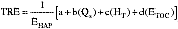
where:
TRE = TRE index value.
EHAP = Hourly emission rate of total organic HAP, kilograms per hour, as calculated in paragraph (d)(1) or (d)(2)(iv) of this section.
Qs = Vent stream flow rate, standard cubic meters per minute, at a standard temperature of 20 °C, as calculated in paragraph (d)(1) or (d)(2)(i) of this section.
HT = Vent stream net heating value, megaJoules per standard cubic meter, as calculated in paragraph (d)(1) or (d)(2)(iii) of this section.
ETOC = Emission rate of TOC (minus methane and ethane), kilograms per hour, as calculated in paragraph (d)(1) or (d)(2)(iv) of this section.
a,b,c,d = Coefficients presented in table 1 of this subpart, selected in accordance with paragraphs (d)(3)(ii) and (iii) of this section.
(ii) The owner or operator of a nonhalogenated vent stream shall calculate the TRE index value based on the use of a flare, a thermal incinerator with 0 percent heat recovery, and a thermal incinerator with 70 percent heat recovery and shall select the lowest TRE index value. The owner or operator shall use the applicable coefficients in table 1 of this subpart for nonhalogenated vent streams located within existing sources and the applicable coefficients in table 2 of this subpart for nonhalogenated vent streams located within new sources.
(iii) The owner or operator of a halogenated vent stream shall calculate the TRE index value based on the use of a thermal incinerator with 0 percent heat recovery, and a scrubber. The owner or operator shall use the applicable coefficients in table 1 of this subpart for halogenated vent streams located within existing sources and the applicable coefficients in table 2 of this subpart for halogenated vent streams located within new sources.
(e) The owner or operator of a Group 2 process vent shall recalculate the TRE index value, flow, or organic hazardous air pollutants concentration for each process vent, as necessary to determine whether the vent is Group 1 or Group 2, whenever process changes are made that could reasonably be expected to change the vent to a Group 1 vent. Examples of process changes include, but are not limited to, changes in production capacity, production rate, feedstock type, or catalyst type, or whenever there is replacement, removal, or addition of recovery equipment. For purposes of this paragraph, process changes do not include: Process upsets; unintentional, temporary process changes; and changes that are within the range on which the original TRE calculation was based.
(1) The TRE index value, flow rate, or organic HAP concentration shall be recalculated based on measurements of vent stream flow rate, TOC, and organic HAP concentrations, and heating values as specified in § 63.115 (a), (b), (c), and (d) of this subpart, as applicable, or on best engineering assessment of the effects of the change. Engineering assessments shall meet the specifications in paragraph (d)(1) of this section.
(2) Where the recalculated TRE index value is less than or equal to 1.0, or less than or equal to 4.0 but greater than 1.0, the recalculated flow rate is greater than or equal to 0.005 standard cubic meter per minute, or the recalculated concentration is greater than or equal to 50 parts per million by volume, the owner or operator shall submit a report as specified in § 63.118 (g), (h), (i), or (j) of this subpart and shall comply with the appropriate provisions in § 63.113 of this subpart by the dates specified in § 63.100 of subpart F of this part.
(f) Notwithstanding any other provisions of this subpart, in any case where a process vent includes one or more gas streams that are not from a source subject to this subpart (hereafter called “non-HON streams” for purposes of this paragraph), and one or more gas streams that meet the criteria in § 63.107(b) through (h) or the criteria in § 63.107(i) (hereafter called “HON streams” for purposes of this paragraph), the owner or operator may elect to comply with paragraphs (f)(1) through (3) of this section.
(1) The owner or operator may determine the characteristics (flow rate, total organic HAP concentration, and TRE index value) for each HON stream, or combination of HON streams, at a representative point as near as practical to, but before, the point at which it is combined with one or more non-HON streams.
(2) If one or more of the HON streams, or combinations of HON streams, has the characteristics (determined at the location specified in paragraph (f)(1) of this section) associated with a Group 1 process vent, the combined vent stream is a Group 1 process vent. Except as specified in paragraph (f)(3) of this section, if none of the HON streams, or combinations of HON streams, when determined at the location specified in paragraph (f)(1) of this section, has the characteristics associated with a Group 1 process vent, the combined vent stream is a Group 2 process vent regardless of the TRE index value determined at the location specified in § 63.115(a). If the combined vent stream is a Group 2 process vent as determined by the previous sentence, but one or more of the HON streams, or combinations of HON streams, has a TRE index value greater than 1 but less than or equal to 4, the combined vent stream is a process vent with a TRE index value greater than 1 but less than or equal to 4. In this case, the owner or operator shall monitor the combined vent stream as required by § 63.114(b).
(3) Paragraphs (f)(1) and (2) of this section are not intended to apply instead of any other subpart of this part. If another subpart of this part applies to one or more of the non-HON streams contributing to the combined vent stream, that subpart may impose emission control requirements such as, but not limited to, requiring the combined vent stream to be classified and controlled as a Group 1 process vent.
[59 FR 19468, Apr. 22, 1994, as amended at 62 FR 2746, Jan. 17, 1997; 66 FR 6931, Jan. 22, 2001]
§ 63.116 Process vent provisions—performance test methods and procedures to determine compliance.
(a) When a flare is used to comply with § 63.113(a)(1), the owner or operator shall comply with paragraphs (a)(1) through (3) of this section. The owner or operator is not required to conduct a performance test to determine percent emission reduction or outlet organic HAP or TOC concentration.
(1) Conduct a visible emission test using the techniques specified in § 63.11(b)(4).
(2) Determine the net heating value of the gas being combusted using the techniques specified in § 63.11(b)(6).
(3) Determine the exit velocity using the techniques specified in either § 63.11(b)(7)(i) (and § 63.11(b)(7)(iii), where applicable) or § 63.11(b)(8), as appropriate.
(b) An owner or operator is not required to conduct a performance test when any control device specified in paragraphs (b)(1) through (b)(5) of this section is used.
(1) A boiler or process heater with a design heat input capacity of 44 megawatts or greater.
(2) A boiler or process heater into which the gas stream is introduced with the primary fuel or is used as the primary fuel.
(3) A control device for which a performance test was conducted for determining compliance with a regulation promulgated by the EPA and the test was conducted using the same methods specified in this section and either no process changes have been made since the test, or the owner or operator can demonstrate that the results of the performance test, with or without adjustments, reliably demonstrate compliance despite process changes.
(4) A boiler or process heater burning hazardous waste for which the owner or operator:
(i) Has been issued a final permit under 40 CFR part 270 and complies with the requirements of 40 CFR part 266, subpart H, or
(ii) Has certified compliance with the interim status requirements of 40 CFR part 266, subpart H.
(5) A hazardous waste incinerator for which the owner or operator has been issued a final permit under 40 CFR part 270 and complies with the requirements of 40 CFR part 264, subpart O, or has certified compliance with the interim status requirements of 40 CFR part 265, subpart O.
(c) Except as provided in paragraphs (a) and (b) of this section, an owner or operator using a control device to comply with the organic HAP concentration limit or percent reduction efficiency requirements in § 63.113(a)(2) of this subpart shall conduct a performance test using the procedures in paragraphs (c)(1) through (c)(4) of this section. The organic HAP concentration and percent reduction may be measured as either total organic HAP or as TOC minus methane and ethane according to the procedures specified.
(1) Method 1 or 1A of 40 CFR part 60, appendix A, as appropriate, shall be used for selection of the sampling sites.
(i) For determination of compliance with the 98 percent reduction of total organic HAP requirement of § 63.113(a)(2) of this subpart, sampling sites shall be located at the inlet of the control device as specified in paragraphs (c)(1)(i)(A) and (c)(1)(i)(B) of this section, and at the outlet of the control device.
(A) The control device inlet sampling site shall be located after the final product recovery device.
(B) If a vent stream is introduced with the combustion air or as a secondary fuel into a boiler or process heater with a design capacity less than 44 megawatts, selection of the location of the inlet sampling sites shall ensure the measurement of total organic HAP or TOC (minus methane and ethane) concentrations in all vent streams and primary and secondary fuels introduced into the boiler or process heater.
(ii) For determination of compliance with the 20 parts per million by volume total organic HAP limit in § 63.113(a)(2) of this subpart, the sampling site shall be located at the outlet of the control device.
(2) The gas volumetric flow rate shall be determined using Method 2, 2A, 2C, or 2D of 40 CFR part 60, appendix A, as appropriate.
(3) To determine compliance with the 20 parts per million by volume total organic HAP limit in § 63.113(a)(2) of this subpart, the owner or operator shall use Method 18 of 40 CFR part 60, appendix A to measure either TOC minus methane and ethane or total organic HAP. Alternatively, any other method or data that has been validated according to the applicable procedures in Method 301 of appendix A of this part, may be used. The following procedures shall be used to calculate parts per million by volume concentration, corrected to 3 percent oxygen:
(i) The minimum sampling time for each run shall be 1 hour in which either an integrated sample or a minimum of four grab samples shall be taken. If grab sampling is used, then the samples shall be taken at approximately equal intervals in time, such as 15 minute intervals during the run.
(ii) The concentration of either TOC (minus methane or ethane) or total organic HAP shall be calculated according to paragraph (c)(3)(ii)(A) or (c)(3)(ii)(B) of this section.
(A) The TOC concentration (CTOC) is the sum of the concentrations of the individual components and shall be computed for each run using the following equation:

where:
CTOC = Concentration of TOC (minus methane and ethane), dry basis, parts per million by volume.
Cji = Concentration of sample components j of sample i, dry basis, parts per million by volume.
n = Number of components in the sample.
x = Number of samples in the sample run.
(B) The total organic HAP concentration (CHAP) shall be computed according to the equation in paragraph (c)(3)(ii)(A) of this section except that only the organic HAP species shall be summed. The list of organic HAP's is provided in table 2 of subpart F of this part.
(iii) The concentration of TOC or total organic HAP shall be corrected to 3 percent oxygen if a combustion device is the control device.
(A) The emission rate correction factor or excess air, integrated sampling and analysis procedures of Method 3B of 40 CFR part 60, appendix A shall be used to determine the oxygen concentration (%O2d). The samples shall be taken during the same time that the TOC (minus methane or ethane) or total organic HAP samples are taken.
(B) The concentration corrected to 3 percent oxygen (Cc) shall be computed using the following equation:

Where:
Cc = Concentration of TOC or organic HAP corrected to 3 percent oxygen, dry basis, parts per million by volume.
Cm = Concentration of TOC (minus methane and ethane) or organic HAP, dry basis, parts per million by volume.
%02d = Concentration of oxygen, dry basis, percent by volume.
(4) To determine compliance with the 98 percent reduction requirement of § 63.113(a)(2) of this subpart, the owner or operator shall use Method 18 of 40 CFR part 60, appendix A; alternatively, any other method or data that has been validated according to the applicable procedures in Method 301 of appendix A of this part may be used. The following procedures shall be used to calculate percent reduction efficiency:
(i) The minimum sampling time for each run shall be 1 hour in which either an integrated sample or a minimum of four grab samples shall be taken. If grab sampling is used, then the samples shall be taken at approximately equal intervals in time such as 15 minute intervals during the run.
(ii) The mass rate of either TOC (minus methane and ethane) or total organic HAP (Ei, Eo) shall be computed.
(A) The following equations shall be used:


where:
Cij, Coj = Concentration of sample component j of the gas stream at the inlet and outlet of the control device, respectively, dry basis, parts per million by volume.
Ei, Eo = Mass rate of TOC (minus methane and ethane) or total organic HAP at the inlet and outlet of the control device, respectively, dry basis, kilogram per hour.
Mij, Moj = Molecular weight of sample component j of the gas stream at the inlet and outlet of the control device, respectively, gram/gram-mole.
Qi, Qo = Flow rate of gas stream at the inlet and outlet of the control device, respectively, dry standard cubic meter per minute.
K2 = Constant, 2.494 × 10⁻⁶ (parts per million)−1 (gram-mole per standard cubic meter) (kilogram/gram) (minute/hour), where standard temperature (gram-mole per standard cubic meter) is 20 °C.
(B) Where the mass rate of TOC is being calculated, all organic compounds (minus methane and ethane) measured by Method 18 of 40 CFR part 60, appendix A are summed using the equation in paragraph (c)(4)(ii)(A) of this section.
(C) Where the mass rate of total organic HAP is being calculated, only the organic HAP species shall be summed using the equation in paragraph (c)(4)(ii)(A) of this section. The list of organic HAP's is provided in table 2 of subpart F of this part.
(iii) The percent reduction in TOC (minus methane and ethane) or total organic HAP shall be calculated as follows:

where:
R = Control efficiency of control device, percent.
Ei = Mass rate of TOC (minus methane and ethane) or total organic HAP at the inlet to the control device as calculated under paragraph (c)(4)(ii) of this section, kilograms TOC per hour or kilograms organic HAP per hour.
Eo = Mass rate of TOC (minus methane and ethane) or total organic HAP at the outlet of the control device, as calculated under paragraph (c)(4)(ii) of this section, kilograms TOC per hour or kilograms organic HAP per hour.
(iv) If the vent stream entering a boiler or process heater with a design capacity less than 44 megawatts is introduced with the combustion air or as a secondary fuel, the weight-percent reduction of total organic HAP or TOC (minus methane and ethane) across the device shall be determined by comparing the TOC (minus methane and ethane) or total organic HAP in all combusted vent streams and primary and secondary fuels with the TOC (minus methane and ethane) or total organic HAP exiting the combustion device, respectively.
(d) An owner or operator using a combustion device followed by a scrubber or other halogen reduction device to control halogenated vent streams in compliance with § 63.113(c)(1) shall conduct a performance test to determine compliance with the control efficiency or emission limits for hydrogen halides and halogens.
(1) For an owner or operator determining compliance with the percent reduction of total hydrogen halides and halogens, sampling sites shall be located at the inlet and outlet of the scrubber or other halogen reduction device used to reduce halogen emissions. For an owner or operator determining compliance with the less than 0.45 kilogram per hour outlet emission limit for total hydrogen halides and halogens, the sampling site shall be located at the outlet of the scrubber or other halogen reduction device and prior to any releases to the atmosphere.
(2) Except as provided in paragraph (d)(5) of this section, Method 26 or Method 26A of 40 CFR part 60, appendix A, shall be used to determine the concentration, in milligrams per dry standard cubic meter, of total hydrogen halides and halogens that may be present in the vent stream. The mass emissions of each hydrogen halide and halogen compound shall be calculated from the measured concentrations and the gas stream flow rate.
(3) To determine compliance with the percent removal efficiency, the mass emissions for any hydrogen halides and halogens present at the inlet of the scrubber or other halogen reduction device shall be summed together. The mass emissions of the compounds present at the outlet of the scrubber or other halogen reduction device shall be summed together. Percent reduction shall be determined by comparison of the summed inlet and outlet measurements.
(4) To demonstrate compliance with the less than 0.45 kilogram per hour outlet emission limit, the test results must show that the mass emission rate of total hydrogen halides and halogens measured at the outlet of the scrubber or other halogen reduction device is below 0.45 kilogram per hour.
(5) The owner or operator may use any other method to demonstrate compliance if the method or data has been validated according to the applicable procedures of Method 301 of appendix A of this part.
(e) An owner or operator using a scrubber or other halogen reduction device to reduce the vent stream halogen atom mass emission rate to less than 0.45 kilogram per hour prior to a combustion control device in compliance with § 63.113(c)(2) of this subpart shall determine the halogen atom mass emission rate prior to the combustor according to the procedures in § 63.115(d)(2)(v) of this subpart.
[59 FR 19468, Apr. 22, 1994, as amended at 62 FR 2746, Jan. 17, 1997; 64 FR 20191, Apr. 26, 1999; 66 FR 6931, Jan. 22, 2001]
§ 63.117 Process vent provisions—reporting and recordkeeping requirements for group and TRE determinations and performance tests.
(a) Each owner or operator subject to the control provisions for Group 1 process vents in § 63.113(a) or the provisions for Group 2 process vents with a TRE index value greater than 1.0 but less than or equal to 4.0 in § 63.113(d) shall:
(1) Keep an up-to-date, readily accessible record of the data specified in paragraphs (a)(4) through (a)(8) of this section, as applicable, and
(2) Include the data in paragraphs (a)(4) through (a)(8) of this section in the Notification of Compliance Status report as specified in § 63.152(b) of this subpart.
(3) If any subsequent TRE determinations or performance tests are conducted after the Notification of Compliance Status has been submitted, report the data in paragraphs (a)(4) through (a)(8) of this section in the next Periodic Report as specified in § 63.152(c) of this subpart.
(4) Record and report the following when using a combustion device to achieve a 98 weight percent reduction in organic HAP or an organic HAP concentration of 20 parts per million by volume, as specified in § 63.113(a)(2) of this subpart:
(i) The parameter monitoring results for incinerators, catalytic incinerators, boilers or process heaters specified in table 3 of this subpart, and averaged over the same time period of the performance testing.
(ii) For an incinerator, the percent reduction of organic HAP or TOC achieved by the incinerator determined as specified in § 63.116(c) of this subpart, or the concentration of organic HAP or TOC (parts per million by volume, by compound) determined as specified in § 63.116(c) of this subpart at the outlet of the incinerator on a dry basis corrected to 3 percent oxygen.
(iii) For a boiler or process heater, a description of the location at which the vent stream is introduced into the boiler or process heater.
(iv) For a boiler or process heater with a design heat input capacity of less than 44 megawatts and where the vent stream is introduced with combustion air or used as a secondary fuel and is not mixed with the primary fuel, the percent reduction of organic HAP or TOC, or the concentration of organic HAP or TOC (parts per million by volume, by compound) determined as specified in § 63.116(c) at the outlet of the combustion device on a dry basis corrected to 3 percent oxygen.
(5) Record and report the following when using a flare to comply with § 63.113(a)(1) of this subpart:
(i) Flare design (i.e., steam-assisted, air-assisted, or non-assisted);
(ii) All visible emission readings, heat content determinations, flow rate measurements, and exit velocity determinations made during the compliance determination required by § 63.116(a) of this subpart; and
(iii) All periods during the compliance determination when the pilot flame is absent.
(6) Record and report the following when using a scrubber following a combustion device to control a halogenated vent stream:
(i) The percent reduction or scrubber outlet mass emission rate of total hydrogen halides and halogens as specified in § 63.116(d) of this subpart;
(ii) The pH of the scrubber effluent; and
(iii) The scrubber liquid to gas ratio.
(7) Record and report the following when achieving and maintaining a TRE index value greater than 1.0 but less than 4.0 as specified in § 63.113(a)(3) or § 63.113(d) of this subpart:
(i) The parameter monitoring results for absorbers, condensers, or carbon adsorbers, as specified in table 4 of this subpart, and averaged over the same time period of the measurements of vent stream flow rate and concentration used in the TRE determination (both measured while the vent stream is normally routed and constituted), and
(ii) The measurements and calculations performed to determine the TRE index value of the vent stream.
(8) Record and report the halogen concentration in the vent stream determined according to the procedures specified in § 63.115(d)(2)(v).
(b) The owner or operator of a Group 2 process vent with a TRE index greater than 4.0 as specified in § 63.113(e) of this subpart, shall maintain records and submit as part of the Notification of Compliance Status specified in § 63.152 of this subpart, measurements, engineering assessments, and calculations performed to determine the TRE index value of the vent stream. Documentation of engineering assessments shall include all data, assumptions, and procedures used for the engineering assessments, as specified in § 63.115(d)(1) of this subpart.
(c) Each owner or operator who elects to demonstrate that a process vent is a Group 2 process vent based on a flow rate less than 0.005 standard cubic meter per minute must submit to the Administrator the flow rate measurement using methods and procedures specified in § 63.115 (a) and (b) of this subpart with the Notification of Compliance Status specified in § 63.152 of this subpart.
(d) Each owner or operator who elects to demonstrate that a process vent is a Group 2 process vent based on organic HAP or TOC concentration less than 50 parts per million by volume must submit to the Administrator an organic HAP or TOC concentration measurement using the methods and procedures specified in § 63.115 (a) and (c) of this subpart with the Notification of Compliance Status specified in § 63.152 of this subpart.
(e) If an owner or operator uses a control or recovery device other than those listed in tables 3 and 4 of this subpart or requests approval to monitor a parameter other than those specified in tables 3 and 4 of this subpart, the owner or operator shall submit a description of planned reporting and recordkeeping procedures as required under § 63.151(f) or § 63.152(e) of this subpart. The Administrator will specify appropriate reporting and recordkeeping requirements as part of the review of the permit application or by other appropriate means.
(f) For each parameter monitored according to tables 3 or 4 of this subpart or paragraph (e) of this section, the owner or operator shall establish a range for the parameter that indicates proper operation of the control or recovery device. In order to establish the range, the information required in § 63.152(b) of this subpart shall be submitted in the Notification of Compliance Status or the operating permit application or amendment.
[59 FR 19468, Apr. 22, 1994, as amended at 61 FR 64576, Dec. 5, 1996; 66 FR 6932, Jan. 22, 2001]
§ 63.118 Process vent provisions—periodic reporting and recordkeeping requirements.
(a) Each owner or operator using a control device to comply with § 63.113 (a)(1) or (a)(2) of this subpart shall keep the following records up-to-date and readily accessible:
(1) Continuous records of the equipment operating parameters specified to be monitored under § 63.114(a) of this subpart and listed in table 3 of this subpart or specified by the Administrator in accordance with § 63.114(c) and § 63.117(e) of this subpart. For flares, the hourly records and records of pilot flame outages specified in table 3 of this subpart shall be maintained in place of continuous records.
(2) Records of the daily average value of each continuously monitored parameter for each operating day determined according to the procedures specified in § 63.152(f). For flares, records of the times and duration of all periods during which all pilot flames are absent shall be kept rather than daily averages.
(3) Hourly records of whether the flow indicator specified under § 63.114(d)(1) was operating and whether a diversion was detected at any time during the hour, as well as records of the times and durations of all periods when the gas stream is diverted to the atmosphere or the monitor is not operating.
(4) Where a seal mechanism is used to comply with § 63.114(d)(2) of this subpart, hourly records of flow are not required. In such cases, the owner or operator shall record that the monthly visual inspection of the seals or closure mechanism has been done, and shall record the duration of all periods when the seal mechanism is broken, the bypass line valve position has changed, or the key for a lock-and-key type lock has been checked out, and records of any car-seal that has broken.
(b) Each owner or operator using a recovery device or other means to achieve and maintain a TRE index value greater than 1.0 but less than 4.0 as specified in § 63.113(a)(3) or § 63.113(d) of this subpart shall keep the following records up-to-date and readily accessible:
(1) Continuous records of the equipment operating parameters specified to be monitored under § 63.114(b) of this subpart and listed in table 4 of this subpart or specified by the Administrator in accordance with § 63.114(c) of this subpart and § 63.114(e) of this subpart and
(2) Records of the daily average value of each continuously monitored parameter for each operating day determined according to the procedures specified in § 63.152(f). If carbon adsorber regeneration stream flow and carbon bed regeneration temperature are monitored, the records specified in table 4 of this subpart shall be kept instead of the daily averages.
(c) Each owner or operator subject to the provisions of this subpart and who elects to demonstrate compliance with the TRE index value greater than 4.0 under § 63.113(e) of this subpart or greater than 1.0 under § 63.113(a)(3) or § 63.113(d) of this subpart shall keep up-to-date, readily accessible records of:
(1) Any process changes as defined in § 63.115(e) of this subpart; and
(2) Any recalculation of the TRE index value pursuant to § 63.115(e) of this subpart.
(d) Each owner or operator who elects to comply by maintining a flow rate less than 0.005 standard cubic meter per minute under § 63.113(f) of this subpart, shall keep up-to-date, readily accessible records of:
(1) Any process changes as defined in § 63.115(e) of this subpart that increase the vent stream flow rate,
(2) Any recalculation or measurement of the flow rate pursuant to § 63.115(e) of this subpart, and
(3) If the flow rate increases to 0.005 standard cubic meter per minute or greater as a result of the process change, the TRE determination performed according to the procedures of § 63.115(d) of this subpart.
(e) Each owner or operator who elects to comply by maintaining an organic HAP concentration less than 50 parts per million by volume organic HAP concentration under § 63.113(g) of this subpart shall keep up-to-date, readily accessible records of:
(1) Any process changes as defined in § 63.115(e) that increase the organic HAP concentration of the vent stream,
(2) Any recalculation or measurement of the concentration pursuant to § 63.115(e) of this subpart, and
(3) If the organic HAP concentration increases to 50 parts per million by volume or greater as a result of the process change, the TRE determination performed according to the procedures of § 63.115(d) of this subpart.
(f) Each owner or operator who elects to comply with the requirements of § 63.113 of this subpart shall submit to the Administrator Periodic Reports of the following recorded information according to the schedule in § 63.152 of this subpart.
(1) Reports of daily average values of monitored parameters for all operating days when the daily average values recorded under paragraphs (a) and (b) of this section were outside the ranges established in the Notification of Compliance Status or operating permit.
(2) For Group 1 points, reports of the duration of periods when monitoring data is not collected for each excursion caused by insufficient monitoring data as defined in § 63.152(c)(2)(ii)(A) of this subpart.
(3) Reports of the times and durations of all periods recorded under paragraph (a)(3) of this section when the gas stream is diverted to the atmosphere through a bypass line.
(4) Reports of all periods recorded under paragraph (a)(4) of this section in which the seal mechanism is broken, the bypass line valve position has changed, or the key to unlock the bypass line valve was checked out.
(5) Reports of the times and durations of all periods recorded under paragraph (a)(2) of this section in which all pilot flames of a flare were absent.
(6) Reports of all carbon bed regeneration cycles during which the parameters recorded under paragraph (b)(2)(v) of this section were outside the ranges established in the Notification of Compliance Status or operating permit.
(g) Whenever a process change, as defined in § 63.115(e) of this subpart, is made that causes a Group 2 process vent to become a Group 1 process vent, the owner or operator shall submit a report within 180 calendar days after the process change as specified in § 63.151(j) of this subpart. The report shall include:
(1) A description of the process change;
(2) The results of the recalculation of the flow rate, organic HAP concentration, and TRE index value required under § 63.115(e) of this subpart and recorded under paragraph (c), (d), or (e) of this section; and
(3) A statement that the owner or operator will comply with the provisions of § 63.113 of this subpart for Group 1 process vents by the dates specified in subpart F of this part.
(h) Whenever a process change, as defined in § 63.115(e) of this subpart, is made that causes a Group 2 process vent with a TRE greater than 4.0 to become a Group 2 process vent with a TRE less than 4.0, the owner or operator shall submit a report within 180 calendar days after the process change. The report may be submitted as part of the next periodic report. The report shall include:
(1) A description of the process change,
(2) The results of the recalculation of the TRE index value required under § 63.115(e) of this subpart and recorded under paragraph (c) of this section, and
(3) A statement that the owner or operator will comply with the requirements specified in § 63.113(d) of this subpart.
(i) Whenever a process change, as defined in § 63.115(e) of this subpart, is made that causes a Group 2 process vent with a flow rate less than 0.005 standard cubic meter per minute to become a Group 2 process vent with a flow rate of 0.005 standard cubic meter per minute or greater and a TRE index value less than or equal to 4.0, the owner or operator shall submit a report within 180 calendar days after the process change. The report may be submitted as part of the next periodic report. The report shall include:
(1) A description of the process change,
(2) The results of the recalculation of the flow rate and the TRE determination required under § 63.115(e) of this subpart and recorded under paragraph (d) of this section, and
(3) A statement that the owner or operator will comply with the requirements specified in § 63.113(d) of this subpart.
(j) Whenever a process change, as defined in § 63.115(e) of this subpart, is made that causes a Group 2 process vent with an organic HAP concentration less than 50 parts per million by volume to become a Group 2 process vent with an organic HAP concentration of 50 parts per million by volume or greater and a TRE index value less than or equal to 4.0, the owner or operator shall submit a report within 180 calendar days after the process change. The report may be submitted as part of the next periodic report. The report shall include:
(1) A description of the process change,
(2) The results of the recalculation of the organic HAP concentration and the TRE determination required under § 63.115(e) of this subpart and recorded under paragraph (e) of this section, and
(3) A statement that the owner or operator will comply with the requirements specified in § 63.113(d) of this subpart.
(k) The owner or operator is not required to submit a report of a process change if one of the conditions listed in paragraph (k)(1), (k)(2), (k)(3), or (k)(4) of this section is met.
(1) The process change does not meet the definition of a process change in § 63.115(e) of this subpart, or
(2) The vent stream flow rate is recalculated according to § 63.115(e) of this subpart and the recalculated value is less than 0.005 standard cubic meter per minute, or
(3) The organic HAP concentration of the vent stream is recalculated according to § 63.115(e) of this subpart and the recalculated value is less than 50 parts per million by volume, or
(4) The TRE index value is recalculated according to § 63.115(e) of this subpart and the recalculated value is greater than 4.0.
[59 FR 19468, Apr. 22, 1994, as amended at 62 FR 2747, Jan. 17, 1997; 66 FR 6932, Jan. 22, 2001]
§ 63.119 Storage vessel provisions—reference control technology.
(a) For each storage vessel to which this subpart applies, the owner or operator shall comply with the requirements of paragraphs (a)(1), (a)(2), (a)(3), and (a)(4) of this section according to the schedule provisions of § 63.100 of subpart F of this part.
(1) For each Group 1 storage vessel (as defined in table 5 of this subpart for existing sources and table 6 of the subpart for new sources) storing a liquid for which the maximum true vapor pressure of the total organic hazardous air pollutants in the liquid is less than 76.6 kilopascals, the owner or operator shall reduce hazardous air pollutants emissions to the atmosphere either by operating and maintaining a fixed roof and internal floating roof, an external floating roof, an external floating roof converted to an internal floating roof, a closed vent system and control device, routing the emissions to a process or a fuel gas system, or vapor balancing in accordance with the requirements in paragraph (b), (c), (d), (e), (f), or (g) of this section, or equivalent as provided in § 63.121 of this subpart.
(2) For each Group 1 storage vessel (as defined in table 5 of this subpart for existing sources and table 6 of this subpart for new sources) storing a liquid for which the maximum true vapor pressure of the total organic hazardous air pollutants in the liquid is greater than or equal to 76.6 kilopascals, the owner or operator shall operate and maintain a closed vent system and control device meeting the requirements specified in paragraph (e) of this section, route the emissions to a process or a fuel gas system as specified in paragraph (f) of this section, vapor balance as specified in paragraph (g) of this section, or equivalent as provided in § 63.121 of this subpart.
(3) For each Group 2 storage vessel that is not part of an emissions average as described in § 63.150 of this subpart, the owner or operator shall comply with the recordkeeping requirement in § 63.123(a) of this subpart and is not required to comply with any other provisions in §§ 63.119 through 63.123 of this subpart.
(4) For each Group 2 storage vessel that is part of an emissions average, the owner or operator shall comply with the emissions averaging provisions in § 63.150 of this subpart.
(b) The owner or operator who elects to use a fixed roof and an internal floating roof, as defined in § 63.111 of this subpart, to comply with the requirements of paragraph (a)(1) of this section shall comply with the requirements specified in paragraphs (b)(1) through (b)(6) of this section.
The intent of paragraphs (b)(1) and (b)(2) of this section is to avoid having a vapor space between the floating roof and the stored liquid for extended periods. Storage vessels may be emptied for purposes such as routine storage vessel maintenance, inspections, petroleum liquid deliveries, or transfer operations. Storage vessels where liquid is left on walls, as bottom clingage, or in pools due to floor irregularity are considered completely empty.
(1) The internal floating roof shall be floating on the liquid surface at all times except when the floating roof must be supported by the leg supports during the periods specified in paragraphs (b)(1)(i) through (b)(1)(iii) of this section.
(i) During the initial fill.
(ii) After the vessel has been completely emptied and degassed.
(iii) When the vessel is completely emptied before being subsequently refilled.
(2) When the floating roof is resting on the leg supports, the process of filling, emptying, or refilling shall be continuous and shall be accomplished as soon as practical.
(3) Each internal floating roof shall be equipped with a closure device between the wall of the storage vessel and the roof edge. Except as provided in paragraph (b)(3)(iv) of this section, the closure device shall consist of one of the devices listed in paragraph (b)(3)(i), (b)(3)(ii), or (b)(3)(iii) of this section.
(i) A liquid-mounted seal as defined in § 63.111 of this subpart.
(ii) A metallic shoe seal as defined in § 63.111 of this subpart.
(iii) Two seals mounted one above the other so that each forms a continuous closure that completely covers the space between the wall of the storage vessel and the edge of the internal floating roof. The lower seal may be vapor- mounted, but both must be continuous seals.
(iv) If the internal floating roof is equipped with a vapor-mounted seal as of December 31, 1992, the requirement for one of the seal options specified in paragraphs (b)(3)(i), (b)(3)(ii), and (b)(3)(iii) of this section does not apply until the earlier of the dates specified in paragraphs (b)(3)(iv)(A) and (b)(3)(iv)(B) of this section.
(A) The next time the storage vessel is emptied and degassed.
(B) No later than 10 years after April 22, 1994.
(4) Automatic bleeder vents are to be closed at all times when the roof is floating, except when the roof is being floated off or is being landed on the roof leg supports.
(5) Except as provided in paragraph (b)(5)(viii) of this section, each internal floating roof shall meet the specifications listed in paragraphs (b)(5)(i) through (b)(5)(vii) of this section.
(i) Each opening in a noncontact internal floating roof except for automatic bleeder vents (vacuum breaker vents) and rim space vents is to provide a projection below the liquid surface.
(ii) Each opening in the internal floating roof except for leg sleeves, automatic bleeder vents, rim space vents, column wells, ladder wells, sample wells, and stub drains shall be equipped with a cover or lid. The cover or lid shall be equipped with a gasket.
(iii) Each penetration of the internal floating roof for the purposes of sampling shall be a sample well. Each sample well shall have a slit fabric cover that covers at least 90 percent of the opening.
(iv) Each automatic bleeder vent shall be gasketed.
(v) Each rim space vent shall be gasketed.
(vi) Each penetration of the internal floating roof that allows for passage of a ladder shall have a gasketed sliding cover.
(vii) Each penetration of the internal floating roof that allows for passage of a column supporting the fixed roof shall have a flexible fabric sleeve seal or a gasketed sliding cover.
(viii) If the internal floating roof does not meet any one of the specifications listed in paragraphs (b)(5)(i) through (b)(5)(vii) of this section as of December 31, 1992, the requirement for meeting those specifications does not apply until the earlier of the dates specified in paragraphs (b)(5)(viii)(A) and (b)(5)(viii)(B) of this section.
(A) The next time the storage vessel is emptied and degassed.
(B) No later than 10 years after April 22, 1994.
(6) Each cover or lid on any opening in the internal floating roof shall be closed (i.e., no visible gaps), except when the cover or lid must be open for access. Covers on each access hatch and each gauge float well shall be bolted or fastened so as to be air-tight when they are closed. Rim space vents are to be set to open only when the internal floating roof is not floating or when the pressure beneath the rim seal exceeds the manufacturer's recommended setting.
(c) The owner or operator who elects to use an external floating roof, as defined in § 63.111 of this subpart, to comply with the requirements of paragraph (a)(1) of this section shall comply with the requirements specified in paragraphs (c)(1) through (c)(4) of this section.
(1) Each external floating roof shall be equipped with a closure device between the wall of the storage vessel and the roof edge.
(i) Except as provided in paragraph (c)(1)(iv) of this section, the closure device is to consist of two seals, one above the other. The lower seal is referred to as the primary seal and the upper seal is referred to as the secondary seal.
(ii) Except as provided in paragraph (c)(1)(v) of this section, the primary seal shall be either a metallic shoe seal or a liquid-mounted seal.
(iii) Except during the inspections required by § 63.120(b) of this subpart, both the primary seal and the secondary seal shall completely cover the annular space between the external floating roof and the wall of the storage vessel in a continuous fashion.
(iv) If the external floating roof is equipped with a liquid-mounted or metallic shoe primary seal as of December 31, 1992, the requirement for a secondary seal in paragraph (c)(1)(i) of this section does not apply until the earlier of the dates specified in paragraphs (c)(1)(iv)(A) and (c)(1)(iv)(B) of this section.
(A) The next time the storage vessel is emptied and degassed.
(B) No later than 10 years after April 22, 1994.
(v) If the external floating roof is equipped with a vapor-mounted primary seal and a secondary seal as of December 31, 1992, the requirement for a liquid-mounted or metallic shoe primary seal in paragraph (c)(1)(ii) of this section does not apply until the earlier of the dates specified in paragraphs (c)(1)(v)(A) and (c)(1)(v)(B) of this section.
(A) The next time the storage vessel is emptied and degassed.
(B) No later than 10 years after April 22, 1994.
(2) Each external floating roof shall meet the specifications listed in paragraphs (c)(2)(i) through (c)(2)(xii) of this section.
(i) Except for automatic bleeder vents (vacuum breaker vents) and rim space vents, each opening in the noncontact external floating roof shall provide a projection below the liquid surface except as provided in paragraph (c)(2)(xii) of this section.
(ii) Except for automatic bleeder vents, rim space vents, roof drains, and leg sleeves, each opening in the roof is to be equipped with a gasketed cover, seal or lid which is to be maintained in a closed position (i.e., no visible gap) at all times except when the cover or lid must be open for access. Covers on each access hatch and each gauge float well shall be bolted or fastened so as to be air-tight when they are closed.
(iii) Automatic bleeder vents are to be closed at all times when the roof is floating, except when the roof is being floated off or is being landed on the roof leg supports.
(iv) Rim space vents are to be set to open only when the roof is being floated off the roof leg supports or when the pressure beneath the rim seal exceeds the manufacturer's recommended setting.
(v) Automatic bleeder vents and rim space vents are to be gasketed.
(vi) Each roof drain that empties into the stored liquid is to be provided with a slotted membrane fabric cover that covers at least 90 percent of the area of the opening.
(vii) Each unslotted guide pole well shall have a gasketed sliding cover or a flexible fabric sleeve seal.
(viii) Each unslotted guide pole shall have on the end of the pole a gasketed cap which is closed at all times except when gauging the liquid level or taking liquid samples.
(ix) Each slotted guide pole well shall have a gasketed sliding cover or a flexible fabric sleeve seal.
(x) Each slotted guide pole shall have a gasketed float or other device which closes off the liquid surface from the atmosphere.
(xi) Each gauge hatch/sample well shall have a gasketed cover which is closed at all times except when the hatch or well must be open for access.
(xii) If each opening in a noncontact external floating roof except for automatic bleeder vents (vacuum breaker vents) and rim space vents does not provide a projection below the liquid surface as of December 31, 1992, the requirement for providing these projections below the liquid surface does not apply until the earlier of the dates specified in paragraphs (c)(2)(xii)(A) and (c)(2)(xii)(B) of this section.
(A) The next time the storage vessel is emptied and degassed.
(B) No later than 10 years after April 22, 1994.
The intent of paragraphs (c)(3) and (c)(4) of this section is to avoid having a vapor space between the floating roof and the stored liquid for extended periods. Storage vessels may be emptied for purposes such as routine storage vessel maintenance, inspections, petroleum liquid deliveries, or transfer operations. Storage vessels where liquid is left on walls, as bottom clingage, or in pools due to floor irregularity are considered completely empty.
(3) The external floating roof shall be floating on the liquid surface at all times except when the floating roof must be supported by the leg supports during the periods specified in paragraphs (c)(3)(i) through (c)(3)(iii) of this section.
(i) During the initial fill.
(ii) After the vessel has been completely emptied and degassed.
(iii) When the vessel is completely emptied before being subsequently refilled.
(4) When the floating roof is resting on the leg supports, the process of filling, emptying, or refilling shall be continuous and shall be accomplished as soon as practical.
(d) The owner or operator who elects to use an external floating roof converted to an internal floating roof (i.e., fixed roof installed above external floating roof) to comply with paragraph (a)(1) of this section shall comply with paragraphs (d)(1) and (d)(2) of this section.
(1) Comply with the requirements for internal floating roof vessels specified in paragraphs (b)(1), (2), and (3) of this section; and
(2) Comply with the requirements for deck fittings that are specified for external floating roof vessels in paragraphs (c)(2)(i) through (c)(2)(xii) of this section.
(e) The owner or operator who elects to use a closed vent system and control device, as defined in § 63.111 of this subpart, to comply with the requirements of paragraph (a)(1) or (a)(2) of this section shall comply with the requirements specified in paragraphs (e)(1) through (e)(5) of this section.
(1) Except as provided in paragraph (e)(2) of this section, the control device shall be designed and operated to reduce inlet emissions of total organic HAP by 95 percent or greater. If a flare is used as the control device, it shall meet the specifications described in the general control device requirements of § 63.11(b) of subpart A of this part.
(2) If the owner or operator can demonstrate that a control device installed on a storage vessel on or before December 31, 1992 is designed to reduce inlet emissions of total organic HAP by greater than or equal to 90 percent but less than 95 percent, then the control device is required to be operated to reduce inlet emissions of total organic HAP by 90 percent or greater.
(3) Periods of planned routine maintenance of the control device, during which the control device does not meet the specifications of paragraph (e)(1) or (e)(2) of this section, as applicable, shall not exceed 240 hours per year.
(4) The specifications and requirements in paragraphs (e)(1) and (e)(2) of this section for control devices do not apply during periods of planned routine maintenance.
(5) The specifications and requirements in paragraphs (e)(1) and (e)(2) of this section for control devices do not apply during a control system malfunction.
(6) An owner or operator may use a combination of control devices to achieve the required reduction of total organic hazardous air pollutants specified in paragraph (e)(1) of this section. An owner or operator may use a combination of control devices installed on a storage vessel on or before December 31, 1992 to achieve the required reduction of total organic hazardous air pollutants specified in paragraph (e)(2) of this section.
(f) The owner or operator who elects to route emissions to a fuel gas system or to a process, as defined in § 63.111 of this subpart, to comply with the requirements of paragraph (a)(1) or (a)(2) of this section shall comply with the requirements in paragraphs (f)(1) through (f)(3) of this section, as applicable.
(1) If emissions are routed to a fuel gas system, there is no requirement to conduct a performance test or design evaluation. If emissions are routed to a process, the organic hazardous air pollutants in the emissions shall predominantly meet one of, or a combination of, the ends specified in paragraphs (f)(1)(i) through (f)(1)(iv) of this section. The owner or operator shall comply with the compliance demonstration requirements in § 63.120(f).
(i) Recycled and/or consumed in the same manner as a material that fulfills the same function in that process;
(ii) Transformed by chemical reaction into materials that are not organic hazardous air pollutants;
(iii) Incorporated into a product; and/or
(iv) Recovered.
(2) If the emissions are conveyed by a system other than hard-piping, any conveyance system operated under positive pressure shall be subject to the requirements of § 63.148 of this subpart.
(3) The fuel gas system or process shall be operating at all times when organic hazardous air pollutants emissions are routed to it except as provided in § 63.102(a)(1) of subpart F of this part and in paragraphs (f)(3)(i) through (f)(3)(iii) of this section. Whenever the owner or operator by-passes the fuel gas system or process, the owner or operator shall comply with the recordkeeping requirement in § 63.123(h) of this subpart. Bypassing is permitted if the owner or operator complies with one or more of the conditions specified in paragraphs (f)(3)(i) through (f)(3)(iii) of this section.
(i) The liquid level in the storage vessel is not increased;
(ii) The emissions are routed through a closed-vent system to a control device complying with § 63.119(e) of this subpart; or
(iii) The total aggregate amount of time during which the emissions by-pass the fuel gas system or process during the calendar year without being routed to a control device, for all reasons (except start-ups/shutdowns/malfunctions or product changeovers of flexible operation units and periods when the storage vessel has been emptied and degassed), does not exceed 240 hours.
(g) The owner or operator who elects to vapor balance to comply with the requirements of paragraphs (a)(1) and (2) of this section shall comply with paragraphs (g)(1) through (7) of this section and the recordkeeping requirements of § 63.123(i).
(1) The vapor balancing system must be designed and operated to route organic HAP vapors displaced from loading of the storage tank to the railcar, tank truck, or barge from which the storage tank is filled.
(2) Tank trucks and railcars must have a current certification in accordance with the U.S. Department of Transportation pressure test requirements of 49 CFR part 180 for tank trucks and 49 CFR 173.31 for railcars. Barges must have a current certification of vapor-tightness through testing in accordance with 40 CFR 63.565.
(3) Hazardous air pollutants must only be unloaded from tank trucks or railcars when vapor collection systems are connected to the storage tank's vapor collection system.
(4) No pressure relief device on the storage tank, or on the railcar or tank truck, shall open during loading or as a result of diurnal temperature changes (breathing losses).
(5) Pressure relief devices must be set to no less than 2.5 psig at all times to prevent breathing losses. Pressure relief devices may be set at values less than 2.5 psig if the owner or operator provides rationale in the notification of compliance status report explaining why the alternative value is sufficient to prevent breathing losses at all times. The owner or operator shall comply with paragraphs (g)(5)(i) through (iii) of this section for each pressure relief valve.
(i) The pressure relief valve shall be monitored quarterly using the method described in § 63.180(b).
(ii) An instrument reading of 500 ppmv or greater defines a leak.
(iii) When a leak is detected, it shall be repaired as soon as practicable, but no later than 5 days after it is detected, and the owner or operator shall comply with the recordkeeping requirements of § 63.181(d)(1) through (4).
(6) Railcars, tank trucks, or barges that deliver HAP to a storage tank must be reloaded or cleaned at a facility that utilizes the control techniques specified in paragraph (g)(6)(i) or (ii) of this section.
(i) The railcar, tank truck, or barge must be connected to a closed-vent system with a control device that reduces inlet emissions of HAP by 95 percent by weight or greater.
(ii) A vapor balancing system designed and operated to collect organic HAP vapor displaced from the tank truck, railcar, or barge during reloading must be used to route the collected HAP vapor to the storage tank from which the liquid being transferred originated.
(7) The owner or operator of the facility where the railcar, tank truck, or barge is reloaded or cleaned must comply with paragraphs (g)(7)(i) through (iii) of this section.
(i) Submit to the owner or operator of the storage tank and to the Administrator a written certification that the reloading or cleaning facility will meet the requirements of this section. The certifying entity may revoke the written certification by sending a written statement to the owner or operator of the storage tank giving at least 90 days notice that the certifying entity is rescinding acceptance of responsibility for compliance with the requirements of this paragraph (g)(7).
(ii) If complying with paragraph (g)(6)(i) of this section, comply with the requirements for closed vent system and control device specified in §§ 63.119 through 63.123. The notification and reporting requirements in § 63.122 do not apply to the owner or operator of the offsite cleaning or reloading facility.
(iii) If complying with paragraph (g)(6)(ii) of this section, keep the records specified in § 63.123(i)(3).
(iv) After the compliance dates specified in § 63.100(k) at an offsite reloading or cleaning facility subject to paragraph (g) of this section, compliance with the monitoring, recordkeeping, and reporting provisions of any other subpart of this part 63 constitutes compliance with the monitoring, recordkeeping, and reporting provisions of paragraph (g)(7)(ii) or paragraph (g)(7)(iii) of this section. You must identify in your Notification of Compliance Status report required by § 63.152(b), the subpart to the part 63 with which the owner or operator of the reloading or cleaning facility complies.
[59 FR 19468, Apr. 22, 1994, as amended at 62 FR 2747, Jan. 17, 1997; 69 FR 76863, Dec. 23, 2004; 71 FR 76614, Dec. 21, 2006]
§ 63.120 Storage vessel provisions—procedures to determine compliance.
(a) To demonstrate compliance with § 63.119(b) of this subpart (storage vessel equipped with a fixed roof and internal floating roof) or with § 63.119(d) of this subpart (storage vessel equipped with an external floating roof converted to an internal floating roof), the owner or operator shall comply with the requirements in paragraphs (a)(1) through (a)(7) of this section.
(1) The owner or operator shall visually inspect the internal floating roof, the primary seal, and the secondary seal (if one is in service), according to the schedule specified in paragraphs (a)(2) and (a)(3) of this section.
(2) For vessels equipped with a single-seal system, the owner or operator shall perform the inspections specified in paragraphs (a)(2)(i) and (a)(2)(ii) of this section.
(i) Visually inspect the internal floating roof and the seal through manholes and roof hatches on the fixed roof at least once every 12 months after initial fill, or at least once every 12 months after the compliance date specified in § 63.100 of subpart F of this part.
(ii) Visually inspect the internal floating roof, the seal, gaskets, slotted membranes, and sleeve seals (if any) each time the storage vessel is emptied and degassed, and at least once every 10 years after the compliance date specified in § 63.100 of subpart F of this part.
(3) For vessels equipped with a double-seal system as specified in § 63.119(b)(3)(iii) of this subpart, the owner or operator shall perform either the inspection required in paragraph (a)(3)(i) of this section or the inspections required in both paragraphs (a)(3)(ii) and (a)(3)(iii) of this section.
(i) The owner or operator shall visually inspect the internal floating roof, the primary seal, the secondary seal, gaskets, slotted membranes, and sleeve seals (if any) each time the storage vessel is emptied and degassed and at least once every 5 years after the compliance date specified in § 63.100 of subpart F of this part; or
(ii) The owner or operator shall visually inspect the internal floating roof and the secondary seal through manholes and roof hatches on the fixed roof at least once every 12 months after initial fill, or at least once every 12 months after the compliance date specified in § 63.100 of subpart F of this part, and
(iii) Visually inspect the internal floating roof, the primary seal, the secondary seal, gaskets, slotted membranes, and sleeve seals (if any) each time the vessel is emptied and degassed and at least once every 10 years after the compliance date specified in § 63.100 of subpart F of this part.
(4) If during the inspections required by paragraph (a)(2)(i) or (a)(3)(ii) of this section, the internal floating roof is not resting on the surface of the liquid inside the storage vessel and is not resting on the leg supports; or there is liquid on the floating roof; or the seal is detached; or there are holes or tears in the seal fabric; or there are visible gaps between the seal and the wall of the storage vessel, the owner or operator shall repair the items or empty and remove the storage vessel from service within 45 calendar days. If a failure that is detected during inspections required by paragraph (a)(2)(i) or (a)(3)(ii) of this section cannot be repaired within 45 calendar days and if the vessel cannot be emptied within 45 calendar days, the owner or operator may utilize up to 2 extensions of up to 30 additional calendar days each. Documentation of a decision to utilize an extension shall include a description of the failure, shall document that alternate storage capacity is unavailable, and shall specify a schedule of actions that will ensure that the control equipment will be repaired or the vessel will be emptied as soon as practical.
(5) Except as provided in paragraph (a)(6) of this section, for all the inspections required by paragraphs (a)(2)(ii), (a)(3)(i), and (a)(3)(iii) of this section, the owner or operator shall notify the Administrator in writing at least 30 calendar days prior to the refilling of each storage vessel to afford the Administrator the opportunity to have an observer present.
(6) If the inspection required by paragraph (a)(2)(ii), (a)(3)(i), or (a)(3)(iii) of this section is not planned and the owner or operator could not have known about the inspection 30 calendar days in advance of refilling the vessel, the owner or operator shall notify the Administrator at least 7 calendar days prior to the refilling of the storage vessel. Notification may be made by telephone and immediately followed by written documentation demonstrating why the inspection was unplanned. Alternatively, the notification including the written documentation may be made in writing and sent so that it is received by the Administrator at least 7 calendar days prior to refilling.
(7) If during the inspections required by paragraph (a)(2)(ii), (a)(3)(i), or (a)(3)(iii) of this section, the internal floating roof has defects; or the primary seal has holes, tears, or other openings in the seal or the seal fabric; or the secondary seal has holes, tears, or other openings in the seal or the seal fabric; or the gaskets no longer close off the liquid surface from the atmosphere; or the slotted membrane has more than 10 percent open area, the owner or operator shall repair the items as necessary so that none of the conditions specified in this paragraph exist before refilling the storage vessel with organic HAP.
(b) To demonstrate compliance with § 63.119(c) of this subpart (storage vessel equipped with an external floating roof), the owner or operator shall comply with the requirements specified in paragraphs (b)(1) through (b)(10) of this section.
(1) Except as provided in paragraph (b)(7) of this section, the owner or operator shall determine the gap areas and maximum gap widths between the primary seal and the wall of the storage vessel, and the secondary seal and the wall of the storage vessel according to the frequency specified in paragraphs (b)(1)(i) through (b)(1)(iii) of this section.
(i) For an external floating roof vessel equipped with primary and secondary seals, measurements of gaps between the vessel wall and the primary seal shall be performed during the hydrostatic testing of the vessel or by the compliance date specified in § 63.100 of subpart F of this part, whichever occurs last, and at least once every 5 years thereafter.
(ii) For an external floating roof vessel equipped with a liquid-mounted or metallic shoe primary seal and without a secondary seal as provided for in § 63.119(c)(1)(iv) of this subpart, measurements of gaps between the vessel wall and the primary seal shall be performed by the compliance date specified in § 63.100 of subpart F of this part and at least once per year thereafter, until a secondary seal is installed. When a secondary seal is installed above the primary seal, measurements of gaps between the vessel wall and both the primary and secondary seals shall be performed within 90 calendar days of installation of the secondary seal, and according to the frequency specified in paragraphs (b)(1)(i) and (b)(1)(iii) of this section thereafter.
(iii) For an external floating roof vessel equipped with primary and secondary seals, measurements of gaps between the vessel wall and the secondary seal shall be performed by the compliance date specified in § 63.100 of subpart F of this part and at least once per year thereafter.
(iv) If any storage vessel ceases to store organic HAP for a period of 1 year or more, or if the maximum true vapor pressure of the total organic HAP's in the stored liquid falls below the values defining Group 1 storage vessels specified in table 5 or table 6 of this subpart for a period of 1 year or more, measurements of gaps between the vessel wall and the primary seal, and gaps between the vessel wall and the secondary seal shall be performed within 90 calendar days of the vessel being refilled with organic HAP.
(2) Except as provided in paragraph (b)(7) of this section, the owner or operator shall determine gap widths and gap areas in the primary and secondary seals (seal gaps) individually by the procedures described in paragraphs (b)(2)(i) through (b)(2)(iii) of this section.
(i) Seal gaps, if any, shall be measured at one or more floating roof levels when the roof is not resting on the roof leg supports.
(ii) Seal gaps, if any, shall be measured around the entire circumference of the vessel in each place where an 0.32 centimeter (1⁄8 inch) diameter uniform probe passes freely (without forcing or binding against the seal) between the seal and the wall of the storage vessel. The circumferential distance of each such location shall also be measured.
(iii) The total surface area of each gap described in paragraph (b)(2)(ii) of this section shall be determined by using probes of various widths to measure accurately the actual distance from the vessel wall to the seal and multiplying each such width by its respective circumferential distance.
(3) The owner or operator shall add the gap surface area of each gap location for the primary seal and divide the sum by the nominal diameter of the vessel. The accumulated area of gaps between the vessel wall and the primary seal shall not exceed 212 square centimeters per meter of vessel diameter and the width of any portion of any gap shall not exceed 3.81 centimeters.
(4) The owner or operator shall add the gap surface area of each gap location for the secondary seal and divide the sum by the nominal diameter of the vessel. The accumulated area of gaps between the vessel wall and the secondary seal shall not exceed 21.2 square centimeters per meter of vessel diameter and the width of any portion of any gap shall not exceed 1.27 centimeters. These seal gap requirements may be exceeded during the measurement of primary seal gaps as required by paragraph (b)(1)(i) and (b)(1)(ii) of this section.
(5) The primary seal shall meet the additional requirements specified in paragraphs (b)(5)(i) and (b)(5)(ii) of this section.
(i) Where a metallic shoe seal is in use, one end of the metallic shoe shall extend into the stored liquid and the other end shall extend a minimum vertical distance of 61 centimeters above the stored liquid surface.
(ii) There shall be no holes, tears, or other openings in the shoe, seal fabric, or seal envelope.
(6) The secondary seal shall meet the additional requirements specified in paragraphs (b)(6)(i) and (b)(6)(ii) of this section.
(i) The secondary seal shall be installed above the primary seal so that it completely covers the space between the roof edge and the vessel wall except as provided in paragraph (b)(4) of this section.
(ii) There shall be no holes, tears, or other openings in the seal or seal fabric.
(7) If the owner or operator determines that it is unsafe to perform the seal gap measurements required in paragraphs (b)(1) and (b)(2) of this section or to inspect the vessel to determine compliance with paragraphs (b)(5) and (b)(6) of this section because the floating roof appears to be structurally unsound and poses an imminent or potential danger to inspecting personnel, the owner or operator shall comply with the requirements in either paragraph (b)(7)(i) or (b)(7)(ii) of this section.
(i) The owner or operator shall measure the seal gaps or inspect the storage vessel no later than 30 calendar days after the determination that the roof is unsafe, or
(ii) The owner or operator shall empty and remove the storage vessel from service no later than 45 calendar days after determining that the roof is unsafe. If the vessel cannot be emptied within 45 calendar days, the owner or operator may utilize up to 2 extensions of up to 30 additional calendar days each. Documentation of a decision to utilize an extension shall include an explanation of why it was unsafe to perform the inspection or seal gap measurement, shall document that alternate storage capacity is unavailable, and shall specify a schedule of actions that will ensure that the vessel will be emptied as soon as practical.
(8) The owner or operator shall repair conditions that do not meet requirements listed in paragraphs (b)(3), (b)(4), (b)(5), and (b)(6) of this section (i.e., failures) no later than 45 calendar days after identification, or shall empty and remove the storage vessel from service no later than 45 calendar days after identification. If during seal gap measurements required in paragraph (b)(1) and (b)(2) of this section or during inspections necessary to determine compliance with paragraphs (b)(5) and (b)(6) of this section a failure is detected that cannot be repaired within 45 calendar days and if the vessel cannot be emptied within 45 calendar days, the owner or operator may utilize up to 2 extensions of up to 30 additional calendar days each. Documentation of a decision to utilize an extension shall include a description of the failure, shall document that alternate storage capacity is unavailable, and shall specify a schedule of actions that will ensure that the control equipment will be repaired or the vessel will be emptied as soon as practical.
(9) The owner or operator shall notify the Administrator in writing 30 calendar days in advance of any gap measurements required by paragraph (b)(1) or (b)(2) of this section to afford the Administrator the opportunity to have an observer present.
(10) The owner or operator shall visually inspect the external floating roof, the primary seal, secondary seal, and fittings each time the vessel is emptied and degassed.
(i) If the external floating roof has defects; the primary seal has holes, tears, or other openings in the seal or the seal fabric; or the secondary seal has holes, tears, or other openings in the seal or the seal fabric; or the gaskets no longer close off the liquid surface from the atmosphere; or the slotted membrane has more than 10 percent open area, the owner or operator shall repair the items as necessary so that none of the conditions specified in this paragraph exist before filling or refilling the storage vessel with organic HAP.
(ii) Except as provided in paragraph (b)(10)(iii) of this section, for all the inspections required by paragraph (b)(10) of this section, the owner or operator shall notify the Administrator in writing at least 30 calendar days prior to filling or refilling of each storage vessel with organic HAP to afford the Administrator the opportunity to inspect the storage vessel prior to refilling.
(iii) If the inspection required by paragraph (b)(10) of this section is not planned and the owner or operator could not have known about the inspection 30 calendar days in advance of refilling the vessel with organic HAP, the owner or operator shall notify the Administrator at least 7 calendar days prior to refilling of the storage vessel. Notification may be made by telephone and immediately followed by written documentation demonstrating why the inspection was unplanned. Alternatively, this notification including the written documentation may be made in writing and sent so that it is received by the Administrator at least 7 calendar days prior to the refilling.
(c) To demonstrate compliance with § 63.119(d) of this subpart (storage vessel equipped with an external floating roof converted to an internal floating roof), the owner or operator shall comply with the requirements of paragraph (a) of this section.
(d) To demonstrate compliance with § 63.119(e) of this subpart (storage vessel equipped with a closed vent system and control device) using a control device other than a flare, the owner or operator shall comply with the requirements in paragraphs (d)(1) through (d)(7) of this section, except as provided in paragraph (d)(8) of this section.
(1) The owner or operator shall either prepare a design evaluation, which includes the information specified in paragraph (d)(1)(i) of this section, or submit the results of a performance test as described in paragraph (d)(1)(ii) of this section.
(i) The design evaluation shall include documentation demonstrating that the control device being used achieves the required control efficiency during reasonably expected maximum filling rate. This documentation is to include a description of the gas stream which enters the control device, including flow and organic HAP content under varying liquid level conditions, and the information specified in paragraphs (d)(1)(i)(A) through (d)(1)(i)(E) of this section, as applicable.
(A) If the control device receives vapors, gases or liquids, other than fuels, from emission points other than storage vessels subject to this subpart, the efficiency demonstration is to include consideration of all vapors, gases, and liquids, other than fuels, received by the control device.
(B) If an enclosed combustion device with a minimum residence time of 0.5 seconds and a minimum temperature of 760 °C is used to meet the emission reduction requirement specified in § 63.119 (e)(1) or (e)(2), as applicable, documentation that those conditions exist is sufficient to meet the requirements of paragraph (d)(1)(i) of this section.
(C) Except as provided in paragraph (d)(1)(i)(B) of this section, for thermal incinerators, the design evaluation shall include the autoignition temperature of the organic HAP, the flow rate of the organic HAP emission stream, the combustion temperature, and the residence time at the combustion temperature.
(D) For carbon adsorbers, the design evaluation shall include the affinity of the organic HAP vapors for carbon, the amount of carbon in each bed, the number of beds, the humidity of the feed gases, the temperature of the feed gases, the flow rate of the organic HAP emission stream, the desorption schedule, the regeneration stream pressure or temperature, and the flow rate of the regeneration stream. For vacuum desorption, pressure drop shall be included.
(E) For condensers, the design evaluation shall include the final temperature of the organic HAP vapors, the type of condenser, and the design flow rate of the organic HAP emission stream.
(ii) If the control device used to comply with § 63.119(e) of this subpart is also used to comply with § 63.113(a)(2), § 63.126(b)(1), or § 63.139(c) of this subpart, the performance test required by § 63.116(c), § 63.128(a), or § 63.139(d)(1) of this subpart is acceptable to demonstrate compliance with § 63.119(e) of this subpart. The owner or operator is not required to prepare a design evaluation for the control device as described in paragraph (d)(1)(i) of this section, if the performance tests meets the criteria specified in paragraphs (d)(1)(ii)(A) and (d)(1)(ii)(B) of this section.
(A) The performance test demonstrates that the control device achieves greater than or equal to the required control efficiency specified in § 63.119 (e)(1) or (e)(2) of this subpart, as applicable; and
(B) The performance test is submitted as part of the Notification of Compliance Status required by § 63.151(b) of this subpart.
(2) The owner or operator shall submit, as part of the Notification of Compliance Status required by § 63.151 (b) of this subpart, a monitoring plan containing the information specified in paragraph (d)(2)(i) of this section and in either (d)(2)(ii) or (d)(2)(iii) of this section.
(i) A description of the parameter or parameters to be monitored to ensure that the control device is being properly operated and maintained, an explanation of the criteria used for selection of that parameter (or parameters), and the frequency with which monitoring will be performed (e.g., when the liquid level in the storage vessel is being raised); and either
(ii) The documentation specified in paragraph (d)(1)(i) of this section, if the owner or operator elects to prepare a design evaluation; or
(iii) The information specified in paragraph (d)(2)(iii) (A) and (B) of this section if the owner or operator elects to submit the results of a performance test.
(A) Identification of the storage vessel and control device for which the performance test will be submitted, and
(B) Identification of the emission point(s) that share the control device with the storage vessel and for which the performance test will be conducted.
(3) The owner or operator shall submit, as part of the Notification of Compliance Status required by § 63.152(b) of this subpart, the information specified in paragraphs (d)(3)(i) and, if applicable, (d)(3)(ii) of this section.
(i) The operating range for each monitoring parameter identified in the monitoring plan. The specified operating range shall represent the conditions for which the control device is being properly operated and maintained.
(ii) Results of the performance test described in paragraph (d)(1)(ii) of this section.
(4) The owner or operator shall demonstrate compliance with the requirements of § 63.119(e)(3) of this subpart (planned routine maintenance of a control device, during which the control device does not meet the specifications of § 63.119 (e)(1) or (e)(2) of this subpart, as applicable, shall not exceed 240 hours per year) by including in each Periodic Report required by § 63.152(c) of this subpart the information specified in § 63.122(g)(1) of this subpart.
(5) The owner or operator shall monitor the parameters specified in the Notification of Compliance Status required in § 63.152(b) of this subpart or in the operating permit and shall operate and maintain the control device such that the monitored parameters remain within the ranges specified in the Notification of Compliance Status.
(6) Except as provided in paragraph (d)(7) of this section, each closed vent system shall be inspected as specified in § 63.148 of this subpart. The initial and annual inspections required by § 63.148(b) of this subpart shall be done during filling of the storage vessel.
(7) For any fixed roof tank and closed vent system that are operated and maintained under negative pressure, the owner or operator is not required to comply with the requirements specified in § 63.148 of this subpart.
(8) A design evaluation or performance test is not required, if the owner or operator uses a combustion device meeting the criteria in paragraph (d)(8)(i), (d)(8)(ii), (d)(8)(iii), or (d)(8)(iv) of this section.
(i) A boiler or process heater with a design heat input capacity of 44 megawatts or greater.
(ii) A boiler or process heater burning hazardous waste for which the owner or operator:
(A) Has been issued a final permit under 40 CFR part 270 and complies with the requirements of 40 CFR part 266, subpart H, or
(B) Has certified compliance with the interim status requirements of 40 CFR part 266, subpart H.
(iii) A hazardous waste incinerator for which the owner or operator has been issued a final permit under 40 CFR part 270 and complies with the requirements of 40 CFR part 264, subpart O or has certified compliance with the interim status requirements of 40 CFR part 265, subpart O.
(iv) A boiler or process heater into which the vent stream is introduced with the primary fuel.
(e) To demonstrate compliance with § 63.119(e) of this subpart (storage vessel equipped with a closed vent system and control device) using a flare, the owner or operator shall comply with the requirements in paragraphs (e)(1) through (e)(6) of this section.
(1) The owner or operator shall perform the compliance determination specified in § 63.11(b) of subpart A of this part.
(2) The owner or operator shall submit, as part of the Notification of Compliance Status required by § 63.152(b) of this subpart, the information specified in paragraphs (e)(2)(i) through (e)(2)(iii) of this section.
(i) Flare design (i.e., steam-assisted, air-assisted, or non-assisted);
(ii) All visible emission readings, heat content determinations, flow rate measurements, and exit velocity determinations made during the compliance determination required by paragraph (e)(1) of this section; and
(iii) All periods during the compliance determination when the pilot flame is absent.
(3) The owner or operator shall demonstrate compliance with the requirements of § 63.119(e)(3) of this subpart (planned routine maintenance of a flare, during which the flare does not meet the specifications of § 63.119(e)(1) of this subpart, shall not exceed 240 hours per year) by including in each Periodic Report required by § 63.152(c) of this subpart the information specified in § 63.122(g)(1) of this subpart.
(4) The owner or operator shall continue to meet the general control device requirements specified in § 63.11(b) of subpart A of this part.
(5) Except as provided in paragraph (e)(6) of this section, each closed vent system shall be inspected as specified in § 63.148 of this subpart. The inspections required to be performed in accordance with § 63.148(c) of this subpart shall be done during filling of the storage vessel.
(6) For any fixed roof tank and closed vent system that is operated and maintained under negative pressure, the owner or operator is not required to comply with the requirements specified in § 63.148 of this subpart.
(f) To demonstrate compliance with § 63.119(f) of this subpart (storage vessel routed to a process), the owner or operator shall prepare a design evaluation (or engineering assessment) that demonstrates the extent to which one or more of the ends specified in § 63.119(f)(1)(i) through (f)(1)(iv) are being met. The owner or operator shall submit the design evaluation as part of the Notification of Compliance Status required by § 63.152(b) of this subpart.
[59 FR 19468, Apr. 22, 1994, as amended at 61 FR 64576, Dec. 5, 1996; 62 FR 2748, Jan. 17, 1997]
§ 63.121 Storage vessel provisions—alternative means of emission limitation.
(a) Determination of equivalence to the reduction in emissions achieved by the requirements of § 63.119 (b), (c), or (d) of this subpart will be evaluated according to § 63.102(b) of subpart F of this part.
(b) The determination of equivalence referred to in paragraph (a) of this section will be based on the application to the Administrator which shall include the information specified in either paragraph (b)(1) or (b)(2) of this section.
(1) Actual emissions tests that use full-size or scale-model storage vessels that accurately collect and measure all organic HAP emissions from a given control technique, and that accurately simulate wind and account for other emission variables such as temperature and barometric pressure, or
(2) An engineering analysis that the Administrator determines is an accurate method of determining equivalence.
§ 63.122 Storage vessel provisions—reporting.
(a) For each Group 1 storage vessel, the owner or operator shall comply with the requirements of paragraphs (a)(1) through (a)(5) of this section.
(1) The owner or operator shall submit an Initial Notification as required by § 63.151(b) of this subpart.
(2) [Reserved]
(3) The owner or operator shall submit a Notification of Compliance Status as required by § 63.152(b) of this subpart and shall submit as part of the Notification of Compliance Status the information specified in paragraph (c) of this section.
(4) The owner or operator shall submit Periodic Reports as required by § 63.152(c) of this subpart and shall submit as part of the Periodic Reports the information specified in paragraphs (d), (e), (f), and (g) of this section.
(5) The owner or operator shall submit, as applicable, other reports as required by § 63.152(d) of this subpart, containing the information specified in paragraph (h) of this section.
(b) An owner or operator who elects to comply with § 63.119(e) of this subpart by using a closed vent system and a control device other than a flare shall submit, as part of the Monitoring Plan, the information specified in § 63.120(d)(2)(i) of this subpart and the information specified in either § 63.120(d)(2)(ii) of this subpart or § 63.120(d)(2)(iii) of this subpart.
(c) An owner or operator who elects to comply with § 63.119(e) of this subpart by using a closed vent system and a control device shall submit, as part of the Notification of Compliance Status required by § 63.152(b) of this subpart, the information specified in either paragraph (c)(1) or (c)(2) of this section. An owner or operator who elects to comply with § 63.119(f) of this subpart by routing emissions to a process or to a fuel gas system shall submit, as part of the Notification of Compliance Status required by § 63.152(b) of this subpart, the information specified in paragraph (c)(3) of this section.
(1) If a control device other than a flare is used, the owner or operator shall submit the information specified in § 63.120(d)(3)(i) and, if applicable, (d)(3)(ii) of this subpart.
(2) If a flare is used, the owner or operator shall submit the information specified in § 63.120(e)(2)(i), (e)(2)(ii), and (e)(2)(iii) of this subpart.
(3) If emissions are routed to a process, the owner or operator shall submit the information specified in § 63.120(f). If emissions are routed to a fuel gas system, the owner or operator shall submit a statement that the emission stream is connected to the fuel gas system and whether the conveyance system is subject to the requirements of § 63.148.
(d) An owner or operator who elects to comply with § 63.119(b) of this subpart by using a fixed roof and an internal floating roof or with § 63.119(d) of this subpart by using an external floating roof converted to an internal floating roof shall submit, as part of the Periodic Report required under § 63.152(c) of this subpart, the results of each inspection conducted in accordance with § 63.120(a) of this subpart in which a failure is detected in the control equipment.
(1) For vessels for which annual inspections are required under § 63.120 (a)(2)(i) or (a)(3)(ii) of this subpart, the specifications and requirements listed in paragraphs (d)(1)(i) through (d)(1)(iii) of this section apply.
(i) A failure is defined as any time in which the internal floating roof is not resting on the surface of the liquid inside the storage vessel and is not resting on the leg supports; or there is liquid on the floating roof; or the seal is detached from the internal floating roof; or there are holes, tears, or other openings in the seal or seal fabric; or there are visible gaps between the seal and the wall of the storage vessel.
(ii) Except as provided in paragraph (d)(1)(iii) of this section, each Periodic Report shall include the date of the inspection, identification of each storage vessel in which a failure was detected, and a description of the failure. The Periodic Report shall also describe the nature of and date the repair was made or the date the storage vessel was emptied.
(iii) If an extension is utilized in accordance with § 63.120(a)(4) of this subpart, the owner or operator shall, in the next Periodic Report, identify the vessel; include the documentation specified in § 63.120(a)(4) of this subpart; and describe the date the storage vessel was emptied and the nature of and date the repair was made.
(2) For vessels for which inspections are required under § 63.120 (a)(2)(ii), (a)(3)(i), or (a)(3)(iii) of this subpart, the specifications and requirements listed in paragraphs (d)(2)(i) and (d)(2)(ii) of this section apply.
(i) A failure is defined as any time in which the internal floating roof has defects; or the primary seal has holes, tears, or other openings in the seal or the seal fabric; or the secondary seal (if one has been installed) has holes, tears, or other openings in the seal or the seal fabric; or the gaskets no longer close off the liquid surface from the atmosphere; or the slotted membrane has more than 10 percent open area.
(ii) Each Periodic Report required under § 63.152(c) of this subpart shall include the date of the inspection, identification of each storage vessel in which a failure was detected, and a description of the failure. The Periodic Report shall also describe the nature of and date the repair was made.
(e) An owner or operator who elects to comply with § 63.119(c) of this subpart by using an external floating roof shall meet the periodic reporting requirements specified in paragraphs (e)(1), (e)(2), and (e)(3) of this section.
(1) The owner or operator shall submit, as part of the Periodic Report required under § 63.152(c) of this subpart, documentation of the results of each seal gap measurement made in accordance with § 63.120(b) of this subpart in which the requirements of § 63.120 (b)(3), (b)(4), (b)(5), or (b)(6) of this subpart are not met. This documentation shall include the information specified in paragraphs (e)(1)(i) through (e)(1)(iv) of this section.
(i) The date of the seal gap measurement.
(ii) The raw data obtained in the seal gap measurement and the calculations described in § 63.120 (b)(3) and (b)(4) of this subpart.
(iii) A description of any condition specified in § 63.120 (b)(5) or (b)(6) of this subpart that is not met.
(iv) A description of the nature of and date the repair was made, or the date the storage vessel was emptied.
(2) If an extension is utilized in accordance with § 63.120(b)(7)(ii) or (b)(8) of this subpart, the owner or operator shall, in the next Periodic Report, identify the vessel; include the documentation specified in § 63.120(b)(7)(ii) or (b)(8) of this subpart, as applicable; and describe the date the vessel was emptied and the nature of and date the repair was made.
(3) The owner or operator shall submit, as part of the Periodic Report required under § 63.152(c) of this subpart, documentation of any failures that are identified during visual inspections required by § 63.120(b)(10) of this subpart. This documentation shall meet the specifications and requirements in paragraphs (e)(3)(i) and (e)(3)(ii) of this section.
(i) A failure is defined as any time in which the external floating roof has defects; or the primary seal has holes, or other openings in the seal or the seal fabric; or the secondary seal has holes, tears, or other openings in the seal or the seal fabric; or the gaskets no longer close off the liquid surface from the atmosphere; or the slotted membrane has more than 10 percent open area.
(ii) Each Periodic Report required under § 63.152(c) of this subpart shall include the date of the inspection, identification of each storage vessel in which a failure was detected, and a description of the failure. The periodic report shall also describe the nature of and date the repair was made.
(f) An owner or operator who elects to comply with § 63.119(d) of this subpart by using an external floating roof converted to an internal floating roof shall comply with the periodic reporting requirements of paragraph (d) of this section.
(g) An owner or operator who elects to comply with § 63.119(e) of this subpart by installing a closed vent system and control device shall submit, as part of the next Periodic Report required by § 63.152(c) of this subpart, the information specified in paragraphs (g)(1) through (g)(3) of this section.
(1) As required by § 63.120(d)(4) and § 63.120(e)(3) of this subpart, the Periodic Report shall include the information specified in paragraphs (g)(1)(i) and (g)(1)(ii) of this section for those planned routine maintenance operations that would require the control device not to meet the requirements of § 63.119 (e)(1) or (e)(2) of this subpart, as applicable.
(i) A description of the planned routine maintenance that is anticipated to be performed for the control device during the next 6 months. This description shall include the type of maintenance necessary, planned frequency of maintenance, and lengths of maintenance periods.
(ii) A description of the planned routine maintenance that was performed for the control device during the previous 6 months. This description shall include the type of maintenance performed and the total number of hours during those 6 months that the control device did not meet the requirements of § 63.119 (e)(1) or (e)(2) of this subpart, as applicable, due to planned routine maintenance.
(2) If a control device other than a flare is used, the Periodic Report shall describe each occurrence when the monitored parameters were outside of the parameter ranges documented in the Notification of Compliance Status in accordance with § 63.120(d)(3)(i) of this subpart. The description shall include the information specified in paragraphs (g)(2)(i) and (g)(2)(ii) of this section.
(i) Identification of the control device for which the measured parameters were outside of the established ranges, and
(ii) Cause for the measured parameters to be outside of the established ranges.
(3) If a flare is used, the Periodic Report shall describe each occurrence when the flare does not meet the general control device requirements specified in § 63.11(b) of subpart A of this part and shall include the information specified in paragraphs (g)(3)(i) and (g)(3)(ii) of this section.
(i) Identification of the flare which does not meet the general requirements specified in § 63.11(b) of subpart A of this part, and
(ii) Reason the flare did not meet the general requirements specified in § 63.11(b) of subpart A of this part.
(h) An owner or operator who elects to comply with § 63.119 (b), (c), or (d) of this subpart shall submit, as applicable, the reports specified in paragraphs (h)(1) and (h)(2) of this section.
(1) In order to afford the Administrator the opportunity to have an observer present, the owner or operator shall notify the Administrator of the refilling of a storage vessel that has been emptied and degassed.
(i) If the storage vessel is equipped with an internal floating roof as specified in § 63.119(b) of this subpart, the notification shall meet the requirements of either § 63.120 (a)(5) or (a)(6) of this subpart, as applicable.
(ii) If the storage vessel is equipped with an external floating roof as specified in § 63.119(c) of this subpart, the notification shall meet the requirements of either § 63.120 (b)(10)(ii) or (b)(10)(iii) of this subpart, as applicable.
(iii) If the storage vessel is equipped with an external floating roof converted into an internal floating roof as specified in § 63.119(d) of this subpart, the notification shall meet the requirements of either § 63.120 (a)(5) or (a)(6) of this subpart, as applicable.
(2) In order to afford the Administrator the opportunity to have an observer present, the owner or operator of a storage vessel equipped with an external floating roof as specified in § 63.119(c) of this subpart shall notify the Administrator of any seal gap measurements. This notification shall meet the requirements of § 63.120(b)(9) of this subpart.
[59 FR 19468, Apr. 22, 1996, as amended at 61 FR 64576, Dec. 5, 1996; 62 FR 2748, Jan. 17, 1997]
§ 63.123 Storage vessel provisions—recordkeeping.
(a) Each owner or operator of a Group 1 or Group 2 storage vessel shall keep readily accessible records showing the dimensions of the storage vessel and an analysis showing the capacity of the storage vessel. This record shall be kept as long as the storage vessel retains Group 1 or Group 2 status and is in operation. For each Group 2 storage vessel, the owner or operator is not required to comply with any other provisions of §§ 63.119 through 63.123 of this subpart other than those required by this paragraph unless such vessel is part of an emissions average as described in § 63.150 of this subpart.
(b) [Reserved]
(c) An owner or operator who elects to comply with § 63.119(b) of this subpart shall keep a record that each inspection required by § 63.120(a) of this subpart was performed.
(d) An owner or operator who elects to comply with § 63.119(c) of this subpart shall keep records describing the results of each seal gap measurement made in accordance with § 63.120(b) of this subpart. The records shall include the date of the measurement, the raw data obtained in the measurement, and the calculations described in § 63.120(b) (3) and (4) of this subpart.
(e) An owner or operator who elects to comply with § 63.119(d) of this subpart shall keep a record that each inspection required by § 63.120 (a) and (c) of this subpart was performed.
(f) An owner or operator who elects to comply with § 63.119(e) of this subpart shall keep in a readily accessible location the records specified in paragraphs (f)(1) and (f)(2) of this section.
(1) A record of the measured values of the parameters monitored in accordance with § 63.120(d)(5) of this subpart.
(2) A record of the planned routine maintenance performed on the control device including the duration of each time the control device does not meet the specifications of § 63.119 (e)(1) or (e)(2) of this subpart, as applicable, due to the planned routine maintenance. Such a record shall include the information specified in paragraphs (f)(2)(i) and (f)(2)(ii) of this section.
(i) The first time of day and date the requirements of § 63.119 (e)(1) or (e)(2) of this subpart, as applicable, were not met at the beginning of the planned routine maintenance, and
(ii) The first time of day and date the requirements of § 63.119 (e)(1) or (e)(2) of this subpart, as applicable, were met at the conclusion of the planned routine maintenance.
(g) An owner or operator who elects to utilize an extension in emptying a storage vessel in accordance with § 63.120 (a)(4), (b)(7)(ii), or (b)(8) of this subpart shall keep in a readily accessible location, the documentation specified in § 63.120 (a)(4), (b)(7)(ii), or (b)(8), as applicable.
(h) An owner or operator who uses the by-pass provisions of § 63.119(f)(3) of this subpart shall keep in a readily accessible location the records specified in paragraphs (h)(1) through (h)(3) of this section.
(1) The reason it was necessary to by-pass the process equipment or fuel gas system;
(2) The duration of the period when the process equipment or fuel gas system was by-passed;
(3) Documentation or certification of compliance with the applicable provisions of § 63.119(f)(3)(i) through § 63.119(f)(3)(iii).
(i) An owner or operator who elects to comply with § 63.119(g) shall keep the records specified in paragraphs (i)(1) through (3) of this section.
(1) A record of the U.S. Department of Transportation certification required by § 63.119(g)(2).
(2) A record of the pressure relief vent setting specified in § 63.119(g)(5).
(3) If complying with § 63.119(g)(6)(ii), keep the records specified in paragraphs (i)(3)(i) and (ii) of this section.
(i) A record of the equipment to be used and the procedures to be followed when reloading the railcar, tank truck, or barge and displacing vapors to the storage tank from which the liquid originates.
(ii) A record of each time the vapor balancing system is used to comply with § 63.119(g)(6)(ii).
[59 FR 19468, Apr. 22, 1996, as amended at 61 FR 64576, Dec. 5, 1996; 62 FR 2748, Jan. 17, 1997; 69 FR 76863, Dec. 23, 2004]
§§ 63.124-63.125 [Reserved]
§ 63.126 Transfer operations provisions—reference control technology.
(a) For each Group 1 transfer rack the owner or operator shall equip each transfer rack with a vapor collection system and control device.
(1) Each vapor collection system shall be designed and operated to collect the organic hazardous air pollutants vapors displaced from tank trucks or railcars during loading, and to route the collected hazardous air pollutants vapors to a process, or to a fuel gas system, or to a control device as provided in paragraph (b) of this section.
(2) Each vapor collection system shall be designed and operated such that organic HAP vapors collected at one loading arm will not pass through another loading arm in the rack to the atmosphere.
(3) Whenever organic hazardous air pollutants emissions are vented to a process, fuel gas system, or control device used to comply with the provisions of this subpart, the process, fuel gas system, or control device shall be operating.
(b) For each Group 1 transfer rack the owner or operator shall comply with paragraph (b)(1), (b)(2), (b)(3), or (b)(4) of this section.
(1) Use a control device to reduce emissions of total organic hazardous air pollutants by 98 weight-percent or to an exit concentration of 20 parts per million by volume, whichever is less stringent. For combustion devices, the emission reduction or concentration shall be calculated on a dry basis, corrected to 3-percent oxygen. If a boiler or process heater is used to comply with the percent reduction requirement, then the vent stream shall be introduced into the flame zone of such a device. Compliance may be achieved by using any combination of combustion, recovery, and/or recapture devices.
(2) Reduce emissions of organic HAP's using a flare.
(i) The flare shall comply with the requirements of § 63.11(b) of subpart A of this part.
(ii) Halogenated vent streams, as defined in § 63.111 of this subpart, shall not be vented to a flare.
(3) Reduce emissions of organic hazardous air pollutants using a vapor balancing system designed and operated to collect organic hazardous air pollutants vapors displaced from tank trucks or railcars during loading; and to route the collected hazardous air pollutants vapors to the storage vessel from which the liquid being loaded originated, or to another storage vessel connected to a common header, or to compress and route to a process collected hazardous air pollutants vapors.
(4) Route emissions of organic hazardous air pollutants to a fuel gas system or to a process where the organic hazardous air pollutants in the emissions shall predominantly meet one of, or a combination of, the ends specified in paragraphs (b)(4)(i) through (b)(4)(iv) of this section.
(i) Recycled and/or consumed in the same manner as a material that fulfills the same function in that process;
(ii) Transformed by chemical reaction into materials that are not organic hazardous air pollutants;
(iii) Incorporated into a product; and/or
(iv) Recovered.
(c) For each Group 2 transfer rack, the owner or operator shall maintain records as required in § 63.130(f). No other provisions for transfer racks apply to the Group 2 transfer rack.
(d) Halogenated emission streams from Group 1 transfer racks that are combusted shall be controlled according to paragraph (d)(1) or (d)(2) of this section. Determination of whether a vent stream is halogenated shall be made using procedures in (d)(3).
(1) If a combustion device is used to comply with paragraph (b)(1) of this section for a halogenated vent stream, then the vent stream exiting the combustion device shall be ducted to a halogen reduction device, including, but not limited to, a scrubber before it is discharged to the atmosphere.
(i) Except as provided in paragraph (d)(1)(ii) of this section, the halogen reduction device shall reduce overall emissions of hydrogen halides and halogens, as defined in § 63.111 of this subpart, by 99 percent or shall reduce the outlet mass emission rate of total hydrogen halides and halogens to 0.45 kilograms per hour or less, whichever is less stringent.
(ii) If a scrubber or other halogen reduction device was installed prior to December 31, 1992, the halogen reduction device shall reduce overall emissions of hydrogen halides and halogens, as defined in § 63.111 of this subpart, by 95 percent or shall reduce the outlet mass of total hydrogen halides and halogens to less than 0.45 kilograms per hour, whichever is less stringent.
(2) A halogen reduction device, such as a scrubber, or other technique may be used to make the vent stream non-halogenated by reducing the vent stream halogen atom mass emission rate to less than 0.45 kilograms per hour prior to any combustion control device used to comply with the requirements of paragraphs (b)(1) or (b)(2) of this section.
(3) In order to determine whether a vent stream is halogenated, the mass emission rate of halogen atoms contained in organic compounds shall be calculated.
(i) The vent stream concentration of each organic compound containing halogen atoms (parts per million by volume by compound) shall be determined based on the following procedures:
(A) Process knowledge that no halogen or hydrogen halides are present in the process, or
(B) Applicable engineering assessment as specified in § 63.115(d)(1)(iii) of this subpart, or
(C) Concentration of organic compounds containing halogens measured by Method 18 of 40 CFR part 60, appendix A, or
(D) Any other method or data that has been validated according to the applicable procedures in Method 301 of appendix A of this part.
(ii) The following equation shall be used to calculate the mass emission rate of halogen atoms:

where:
E = Mass of halogen atoms, dry basis, kilograms per hour.
K2 = Constant, 2.494 × 10⁻⁶ (parts per million)−1 (kilogram-mole per standard cubic meter) (minute/hour), where standard temperature is 20 °C.
Cj = Concentration of halogenated compound j in the gas stream, dry basis, parts per million by volume.
Mji = Molecular weight of halogen atom i in compound j of the gas stream, kilogram per kilogram-mole.
Lji = Number of atoms of halogen i in compound j of the gas stream.
Vs = Flow rate of gas stream, dry standard cubic meters per minute, determined according to § 63.128(a)(8) of this subpart.
j = Halogenated compound j in the gas stream.
i = Halogen atom i in compound j of the gas stream.
n = Number of halogenated compounds j in the gas stream.
m = Number of different halogens i in each compound j of the gas stream.
(e) For each Group 1 transfer rack the owner or operator shall load organic HAP's into only tank trucks and railcars which:
(1) Have a current certification in accordance with the U. S. Department of Transportation pressure test requirements of 49 CFR part 180 for tank trucks and 49 CFR 173.31 for railcars; or
(2) Have been demonstrated to be vapor-tight within the preceding 12 months, as determined by the procedures in § 63.128(f) of this subpart. Vapor-tight means that the truck or railcar tank will sustain a pressure change of not more than 750 pascals within 5 minutes after it is pressurized to a minimum of 4,500 pascals.
(f) The owner or operator of a transfer rack subject to the provisions of this subpart shall load organic HAP's to only tank trucks or railcars equipped with vapor collection equipment that is compatible with the transfer rack's vapor collection system.
(g) The owner or operator of a transfer rack subject to this subpart shall load organic HAP's to only tank trucks or railcars whose collection systems are connected to the transfer rack's vapor collection systems.
(h) The owner or operator of a transfer rack subject to the provisions of this subpart shall ensure that no pressure-relief device in the transfer rack's vapor collection system or in the organic hazardous air pollutants loading equipment of each tank truck or railcar shall begin to open during loading. Pressure relief devices needed for safety purposes are not subject to this paragraph.
(i) Each valve in the vent system that would divert the vent stream to the atmosphere, either directly or indirectly, shall be secured in a non-diverting position using a carseal or a lock-and-key type configuration, or shall be equipped with a flow indicator. Equipment such as low leg drains, high point bleeds, analyzer vents, open-ended valves or lines, and pressure relief devices needed for safety purposes is not subject to this paragraph.
[59 FR 19468, Apr. 22, 1994, as amended at 62 FR 2749, Jan. 17, 1997]
§ 63.127 Transfer operations provisions—monitoring requirements.
(a) Each owner or operator of a Group 1 transfer rack equipped with a combustion device used to comply with the 98 percent total organic hazardous air pollutants reduction or 20 parts per million by volume outlet concentration requirements in § 63.126(b)(1) of this subpart shall install, calibrate, maintain, and operate according to the manufacturers' specifications (or other written procedures that provide adequate assurance that the equipment would reasonably be expected to monitor accurately) the monitoring equipment specified in paragraph (a)(1), (a)(2), (a)(3), or (a)(4) of this section, as appropriate.
(1) Where an incinerator is used, a temperature monitoring device equipped with a continuous recorder is required.
(i) Where an incinerator other than a catalytic incinerator is used, a temperature monitoring device shall be installed in the firebox or in the ductwork immediately downstream of the firebox in a position before any substantial heat exchange occurs.
(ii) Where a catalytic incinerator is used, temperature monitoring devices shall be installed in the gas stream immediately before and after the catalyst bed.
(2) Where a flare is used, a device (including but not limited to a thermocouple, infrared sensor, or an ultra-violet beam sensor) capable of continuously detecting the presence of a pilot flame is required.
(3) Where a boiler or process heater with a design heat input capacity less than 44 megawatts is used, a temperature monitoring device in the firebox equipped with a continuous recorder is required. Any boiler or process heater in which all vent streams are introduced with the primary fuel or are used as the primary fuel is exempt from this requirement.
(4) Where a scrubber is used with an incinerator, boiler, or process heater in the case of halogenated vent streams, the following monitoring equipment is required for the scrubber:
(i) A pH monitoring device equipped with a continuous recorder shall be installed to monitor the pH of the scrubber effluent.
(ii) A flow meter equipped with a continuous recorder shall be located at the scrubber influent for liquid flow. Gas stream flow shall be determined using one of the procedures specified in paragraphs (a)(4)(ii)(A) through (a)(4)(ii)(C) of this section.
(A) The owner or operator may determine gas stream flow using the design blower capacity, with appropriate adjustments for pressure drop.
(B) If the scrubber is subject to regulations in 40 CFR parts 264 through 266 that have required a determination of the liquid to gas (L/G) ratio prior to the applicable compliance date for this subpart specified in § 63.100(k) of subpart F of this part, the owner or operator may determine gas stream flow by the method that had been utilized to comply with those regulations. A determination that was conducted prior to the compliance date for this subpart may be utilized to comply with this subpart if it is still representative.
(C) The owner or operator may prepare and implement a gas stream flow determination plan that documents an appropriate method which will be used to determine the gas stream flow. The plan shall require determination of gas stream flow by a method which will at least provide a value for either a representative or the highest gas stream flow anticipated in the scrubber during representative operating conditions other than start-ups, shutdowns, or malfunctions. The plan shall include a description of the methodology to be followed and an explanation of how the selected methodology will reliably determine the gas stream flow, and a description of the records that will be maintained to document the determination of gas stream flow. The owner or operator shall maintain the plan as specified in § 63.103(c).
(b) Each owner or operator of a Group 1 transfer rack that uses a recovery device or recapture device to comply with the 98-percent organic hazardous air pollutants reduction or 20 parts per million by volume hazardous air pollutants concentration requirements in § 63.126(b)(1) of this subpart shall install either an organic monitoring device equipped with a continuous recorder, or the monitoring equipment specified in paragraph (b)(1), (b)(2), or (b)(3) of this section, depending on the type of recovery device or recapture device used. All monitoring equipment shall be installed, calibrated, and maintained according to the manufacturer's specifications or other written procedures that provide adequate assurance that the equipment would reasonably be expected to monitor accurately.
(1) Where an absorber is used, a scrubbing liquid temperature monitoring device equipped with a continuous recorder shall be used; and a specific gravity monitoring device equipped with a continuous recorder shall be used.
(2) Where a condenser is used, a condenser exit (product side) temperature monitoring device equipped with a continuous recorder shall be used.
(3) Where a carbon adsorber is used, an integrating regeneration stream flow monitoring device having an accuracy of ±10 percent or better, capable of recording the total regeneration stream mass flow for each regeneration cycle; and a carbon bed temperature monitoring device, capable of recording the temperature of the carbon bed after regeneration and within 15 minutes of completing any cooling cycle shall be used.
(c) An owner or operator of a Group 1 transfer rack may request approval to monitor parameters other than those listed in paragraph (a) or (b) of this section. The request shall be submitted according to the procedures specified in § 63.151(f) or § 63.152(e) of this subpart. Approval shall be requested if the owner or operator:
(1) Seeks to demonstrate compliance with the standards specified in § 63.126(b) of this subpart with a control device other than an incinerator, boiler, process heater, flare, absorber, condenser, or carbon adsorber; or
(2) Uses one of the control devices listed in paragraphs (a) and (b) of this section, but seeks to monitor a parameter other than those specified in paragraphs (a) and (b) of this subpart.
(d) The owner or operator of a Group 1 transfer rack using a vent system that contains by-pass lines that could divert a vent stream flow away from the control device used to comply with § 63.126(b) of this subpart shall comply with paragraph (d)(1) or (d)(2) of this section. Equipment such as low leg drains, high point bleeds, analyzer vents, open-ended valves or lines, and pressure relief valves needed for safety purposes are not subject to this paragraph.
(1) Properly install, maintain, and operate a flow indicator that takes a reading at least once every 15 minutes. Records shall be generated as specified in § 63.130(b) of this subpart. The flow indicator shall be installed at the entrance to any by-pass line that could divert the vent stream away from the control device to the atmosphere; or
(2) Secure the by-pass line valve in the closed position with a car-seal or a lock-and-key type configuration.
(i) A visual inspection of the seal or closure mechanism shall be performed at least once every month to ensure that the valve is maintained in the closed position and the vent stream is not diverted through the by-pass line.
(ii) If a car-seal has been broken or a valve position changed, the owner or operator shall record that the vent stream has been diverted. The car-seal or lock-and-key combination shall be returned to the secured position as soon as practicable but not later than 15 calendar days after the change in position is detected.
(e) The owner or operator shall establish a range that indicates proper operation of the control device for each parameter monitored under paragraphs (a), (b), and (c) of this section. In order to establish the range, the information required in § 63.152(b)(2) of this subpart shall be submitted in the Notification of Compliance Status or the operating permit application or amendment.
[59 FR 19468, Apr. 22, 1994, as amended at 62 FR 2749, Jan. 17, 1997]
§ 63.128 Transfer operations provisions—test methods and procedures.
(a) A performance test is required for determining compliance with the reduction of total organic HAP emissions in § 63.126(b) of this subpart for all control devices except as specified in paragraph (c) of this section. Performance test procedures are as follows:
(1) For control devices shared between transfer racks and process vents, the performance test procedures in § 63.116(c) of this subpart shall be followed.
(2) A performance test shall consist of three runs.
(3) All testing equipment shall be prepared and installed as specified in the appropriate test methods.
(4) For control devices shared between multiple arms that load simultaneously, the minimum sampling time for each run shall be 1 hour in which either an integrated sample or a minimum of four grab samples shall be taken. If grab sampling is used, then the samples shall be taken at approximately equal intervals in time, such as 15-minute intervals during the run.
(5) For control devices that are capable of continuous vapor processing but do not meet the conditions in (a)(7)(i)(B) of this section.
(A) Sampling sites shall be located at the inlet and outlet of the control device, except as provided in paragraph (a)(7)(i)(B) of this section.
(B) If a vent stream is introduced with the combustion air or as a secondary fuel into a boiler or process heater with a design capacity less than 44 megawatts, selection of paragraph (a)(1) or (a)(4) of this section, each run shall represent at least one complete filling period, during which liquid organic HAP's are loaded, and samples shall be collected using integrated sampling or grab samples taken at least four times per hour at approximately equal intervals of time, such as 15-minute intervals.
(6) For intermittent vapor processing systems that do not meet the conditions in paragraph (a)(1) or (a)(4) of this section, each run shall represent at least one complete control device cycle, and samples shall be collected using integrated sampling or grab samples taken at least four times per hour at approximately equal intervals of time, such as 15-minute intervals.
(7) Method 1 or 1A of 40 CFR part 60, appendix A, as appropriate, shall be used for selection of sampling sites.
(i) For an owner or operator complying with the 98-percent total organic HAP reduction requirements in § 63.126(b)(1) of this subpart, sampling sites shall be located as specified in paragraph (a)(7)(i)(A) or (a)(7)(i)(B) of this section.
(A) Sampling sites shall be located at the inlet and outlet of the control device, except as provided in paragraph (a)(7)(i)(B) of this section.
(B) If a vent stream is introduced with the combustion air or as a secondary fuel into a boiler or process heater with a design capacity less than 44 megawatts, selection of the location of the inlet sampling sites shall ensure the measurement of total organic HAP or TOC (minus methane and ethane) concentrations in all vent streams and primary and secondary fuels introduced into the boiler or process heater. A sampling site shall also be located at the outlet of the boiler or process heater.
(ii) For an owner or operator complying with the 20 parts per million by volume limit in § 63.126(b)(1) of this subpart, the sampling site shall be located at the outlet of the control device.
(8) The volumetric flow rate, in standard cubic meters per minute at 20 °C, shall be determined using Method 2, 2A, 2C, or 2D of 40 CFR part 60, appendix A as appropriate.
(9) For the purpose of determining compliance with the 20 parts per million by volume limit in § 63.126(b)(1), Method 18 or Method 25A of 40 CFR part 60, appendix A shall be used to measure either organic compound concentration or organic HAP concentration, except as provided in paragraph (a)(11) of this section.
(i) If Method 25A of 40 CFR part 60, appendix A is used, the following procedures shall be used to calculate the concentration of organic compounds (CT):
(A) The principal organic HAP in the vent stream shall be used as the calibration gas.
(B) The span value for Method 25A of 40 CFR part 60, appendix A shall be between 1.5 and 2.5 times the concentration being measured.
(C) Use of Method 25A of 40 CFR part 60, appendix A is acceptable if the response from the high-level calibration gas is at least 20 times the standard deviation of the response from the zero calibration gas when the instrument is zeroed on the most sensitive scale.
(D) The concentration of TOC shall be corrected to 3 percent oxygen using the procedures and equation in paragraph (a)(9)(v) of this section.
(ii) If Method 18 of 40 CFR part 60, appendix A is used to measure the concentration of organic compounds, the organic compound concentration (CT) is the sum of the individual components and shall be computed for each run using the following equation:

where:
CT = Total concentration of organic compounds (minus methane and ethane), dry basis, parts per million by volume.
Cj = Concentration of sample components j, dry basis, parts per million by volume.
n = Number of components in the sample.
(iii) If an owner or operator uses Method 18 of 40 CFR part 60, appendix A to compute total organic HAP concentration rather than organic compounds concentration, the equation in paragraph (a)(9)(ii) of this section shall be used except that only organic HAP species shall be summed. The list of organic HAP's is provided in table 2 of subpart F of this part.
(iv) The emission rate correction factor or excess air, integrated sampling and analysis procedures of Method 3B of 40 CFR part 60, appendix A shall be used to determine the oxygen concentration. The sampling site shall be the same as that of the organic hazardous air pollutants or organic compound samples, and the samples shall be taken during the same time that the organic hazardous air pollutants or organic compound samples are taken.
(v) The organic compound concentration corrected to 3 percent oxygen (Cc) shall be calculated using the following equation:

where:
Cc = Concentration of organic compounds corrected to 3 percent oxygen, dry basis, parts per million by volume.
CT = Total concentration of organic compounds, dry basis, parts per million by volume.
%O2d = Concentration of oxygen, dry basis, percent by volume.
(10) For the purpose of determining compliance with the 98-percent reduction requirement in § 63.126(b)(1) of this subpart, Method 18 or Method 25A of 40 CFR part 60, appendix A shall be used, except as provided in paragraph (a)(11) of this section.
(i) For the purpose of determining compliance with the reduction efficiency requirement, organic compound concentration may be measured in lieu of organic HAP concentration.
(ii) If Method 25A of 40 CFR part 60, appendix A is used to measure the concentration of organic compounds (CT), the principal organic HAP in the vent stream shall be used as the calibration gas.
(A) An emission testing interval shall consist of each 15-minute period during the performance test. For each interval, a reading from each measurement shall be recorded.
(B) The average organic compound concentration and the volume measurement shall correspond to the same emissions testing interval.
(C) The mass at the inlet and outlet of the control device during each testing interval shall be calculated as follows:
Mj = FKVs CT
where:
Mj = Mass of organic compounds emitted during testing interval j, kilograms.
Vs = Volume of air-vapor mixture exhausted at standard conditions, 20 °C and 760 millimeters mercury, standard cubic meters.
CT = Total concentration of organic compounds (as measured) at the exhaust vent, parts per million by volume, dry basis.
K = Density, kilograms per standard cubic meter organic HAP. 659 kilograms per standard cubic meter organic HAP. (Note: The density term cancels out when the percent reduction is calculated. Therefore, the density used has no effect. The density of hexane is given so that it can be used to maintain the units of Mj.)
F = 10−6 = Conversion factor, (cubic meters organic HAP per cubic meters air) * (parts per million by volume)−1.
(D) The organic compound mass emission rates at the inlet and outlet of the control device shall be calculated as follows:


where:
Ei, Eo = Mass flow rate of organic compounds at the inlet (i) and outlet (o) of the combustion or recovery device, kilograms per hour.
Mij, Moj = Mass of organic compounds at the inlet (i) or outlet (o) during testing interval j, kilograms.
T = Total time of all testing intervals, hours.
n = Number of testing intervals.
(iii) If Method 18 of 40 CFR part 60, appendix A is used to measure organic compounds, the mass rates of organic compounds (Ei, Eo) shall be computed using the following equations:


where:
Cij, Coj = Concentration of sample component j of the gas stream at the inlet and outlet of the control device, respectively, dry basis, parts per million by volume.
MWij, MWoj = Molecular weight of sample component j of the gas stream at the inlet and outlet of the control device, respectively, gram/gram-mole.
Qi, Qo = Flow rate of gas stream at the inlet and outlet of the control device, respectively, dry standard cubic meter per minute.
K2 = Constant, 2.494 × 10⁻⁶ (parts per million)−1 (gram-mole per standard cubic meter) (kilogram/gram) (minute/hour), where standard temperature for (gram-mole per standard cubic meter) is 20 °C.
(iv) Where Method 18 or 25A of 40 CFR part 60, appendix A is used to measure the percent reduction in organic compounds, the percent reduction across the control device shall be calculated as follows:

where:
R = Control efficiency of control device, percent.
Ei = Mass emitted or mass flow rate of organic compounds at the inlet to the combustion or recovery device as calculated under paragraph (a)(10)(ii)(D) or (a)(10)(iii) of this section, kilogram per hour.
Eo = Mass emitted or mass flow rate of organic compounds at the outlet of the combustion or recovery device, as calculated under paragraph (a)(10)(ii)(D) or (a)(10)(iii) of this section, kilogram per hour.
(11) The owner or operator may use any methods or data other than Method 18 or Method 25A of 40 CFR part 60, appendix A, if the method or data has been validated according to Method 301 of appendix A of this part.
(b) When a flare is used to comply with § 63.126(b)(2), the owner or operator shall comply with paragraphs (b)(1) through (3) of this section. The owner or operator is not required to conduct a performance test to determine percent emission reduction or outlet organic HAP or TOC concentration.
(1) Conduct a visible emission test using the techniques specified in § 63.11(b)(4). The observation period shall be as specified in paragraph (b)(1)(i) or (ii) of this section instead of the 2-hour period specified in § 63.11(b)(4).
(i) If the loading cycle is less than 2 hours, then the observation period for that run shall be for the entire loading cycle.
(ii) If additional loading cycles are initiated within the 2-hour period, then visible emission observations shall be conducted for the additional cycles.
(2) Determine the net heating value of the gas being combusted, using the techniques specified in § 63.11(b)(6).
(3) Determine the exit velocity using the techniques specified in either § 63.11(b)(7)(i) (and § 63.11(b)(7)(iii), where applicable) or § 63.11(b)(8), as appropriate.
(c) An owner or operator is not required to conduct a performance test when any of the conditions specified in paragraphs (c)(1) through (c)(7) of this section are met.
(1) When a boiler or process heater with a design heat input capacity of 44 megawatts or greater is used.
(2) When a boiler or process heater burning hazardous waste is used for which the owner or operator:
(i) Has been issued a final permit under 40 CFR part 270 and complies with the requirements of 40 CFR part 266, subpart H, or
(ii) Has certified compliance with the interim status requirements of 40 CFR part 266 subpart H.
(3) When emissions are routed to a fuel gas system or when a boiler or process heater is used and the vent stream is introduced with the primary fuel.
(4) When a vapor balancing system is used.
(5) When emissions are recycled to a chemical manufacturing process unit.
(6) When a transfer rack transfers less than 11.8 million liters per year and the owner or operator complies with the requirements in paragraph (h) of this section or uses a flare to comply with § 63.126(b)(2) of this subpart.
(7) When a hazardous waste incinerator is used for which the owner or operator has been issued a final permit under 40 CFR part 270 and complies with the requirements of 40 CFR part 264, subpart O, or has certified compliance with the interim status requirements 40 CFR part 265, subpart O.
(d) An owner or operator using a combustion device followed by a scrubber or other halogen reduction device to control a halogenated transfer vent stream in compliance with § 63.126(d) of this subpart shall conduct a performance test to determine compliance with the control efficiency or emission limits for hydrogen halides and halogens.
(1) For an owner or operator determining compliance with the percent reduction of total hydrogen halides and halogens, sampling sites shall be located at the inlet and outlet of the scrubber or other halogen reduction device used to reduce halogen emissions. For an owner or operator complying with the 0.45 kilogram per hour outlet mass emission rate limit for total hydrogen halides and halogens, the sampling site shall be located at the outlet of the scrubber or other halogen reduction device and prior to release to the atmosphere.
(2) Except as provided in paragraph (d)(5) of this section, Method 26 or 26A of 40 CFR part 60, appendix A, shall be used to determine the concentration in milligrams per dry standard cubic meter of the hydrogen halides and halogens that may be present in the stream. The mass emission rate of each hydrogen halide and halogen compound shall be calculated from the concentrations and the gas stream flow rate.
(3) To determine compliance with the percent emissions reduction limit, the mass emission rate for any hydrogen halides and halogens present at the scrubber inlet shall be summed together. The mass emission rate of the compounds present at the scrubber outlet shall be summed together. Percent reduction shall be determined by comparison of the summed inlet and outlet measurements.
(4) To demonstrate compliance with the 0.45 kilograms per hour mass emission rate limit, the test results must show that the mass emission rate of the total hydrogen halides and halogens measured at the scrubber outlet is below 0.45 kilograms per hour.
(5) The owner or operator may use any other method or data to demonstrate compliance if the method or data has been validated according to the protocol of Method 301 of appendix A of this part.
(e) The owner or operator shall inspect the vapor collection system and vapor balancing system, according to the requirements for vapor collection systems in § 63.148 of this subpart.
(1) Inspections shall be performed only while a tank truck or railcar is being loaded.
(2) For vapor collection systems only, an inspection shall be performed prior to each performance test required to demonstrate compliance with § 63.126(b)(1) of this subpart.
(3) For each vapor collection system that is operated and maintained under negative pressure, the owner or operator is not required to comply with the requirements specified in § 63.148 of this subpart.
(f) For the purposes of demonstrating vapor tightness to determine compliance with § 63.126(e)(2) of this subpart, the following procedures and equipment shall be used:
(1) The pressure test procedures specified in Method 27 of 40 CFR part 60, appendix A; and
(2) A pressure measurement device which has a precision of #1B2.5 millimeters of mercury or better and which is capable of measuring above the pressure at which the tank truck or railcar is to be tested for vapor tightness.
(g) An owner or operator using a scrubber or other halogen reduction device to reduce the vent stream halogen atom mass emission rate to less than 0.45 kilograms per hour prior to a combustion device used to comply with § 63.126(d)(2) shall determine the halogen atom mass emission rate prior to the combustor according to the procedures in paragraph (d)(3) of this section.
(h) For transfer racks that transfer less than 11.8 million liters per year of liquid organic HAP's, the owner or operator may comply with the requirements in paragraphs (h)(1) through (h)(3) of this section instead of the requirements in paragraph (a) or (b) of this section.
(1) The owner or operator shall prepare, as part of the Notification of Compliance Status required by § 63.152(b) of this subpart, a design evaluation that shall document that the control device being used achieves the required control efficiency during reasonably expected maximum loading conditions. This documentation is to include a description of the gas stream which enters the control device, including flow and organic HAP content, and the information specified in paragraphs (h)(1)(i) through (h)(1)(v) of this section, as applicable.
(i) If the control device receives vapors, gases, or liquids, other than fuels, from emission points other than transfer racks subject to this subpart, the efficiency demonstration is to include consideration of all vapors, gases, and liquids, other than fuels, received by the control device.
(ii) If an enclosed combustion device with a minimum residence time of 0.5 seconds and a minimum temperature of 760 degrees Celsius is used to meet the 98-percent emission reduction requirement, documentation that those conditions exist is sufficient to meet the requirements of paragraph (h)(1) of this section.
(iii) Except as provided in paragraph (h)(1)(ii) of this section, for thermal incinerators, the design evaluation shall include the autoignition temperature of the organic HAP, the flow rate of the organic HAP emission stream, the combustion temperature, and the residence time at the combustion temperature.
(iv) For carbon adsorbers, the design evaluation shall include the affinity of the organic HAP vapors for carbon, the amount of carbon in each bed, the number of beds, the humidity of the feed gases, the temperature of the feed gases, the flow rate of the organic HAP emission stream, the desorption schedule, the regeneration stream pressure or temperature, and the flow rate of the regeneration stream. For vacuum desorption, pressure drop shall be included.
(v) For condensers, the design evaluation shall include the final temperature of the organic HAP vapors, the type of condenser, and the design flow rate of the organic HAP emission stream.
(2) The owner or operator shall submit, as part of the Notification of Compliance Status required by § 63.152(b) of this subpart, the operating range for each monitoring parameter identified for each control device. The specified operating range shall represent the conditions for which the control device can achieve the 98-percent-or-greater emission reduction required by § 63.126(b)(1) of this subpart.
(3) The owner or operator shall monitor the parameters specified in the Notification of Compliance Status required in § 63.152(b) of this subpart or operating permit and shall operate and maintain the control device such that the monitored parameters remain within the ranges specified in the Notification of Compliance Status, except as provided in §§ 63.152(c) and 63.152(f) of this subpart.
[59 FR 19468, Apr. 22, 1994, as amended at 61 FR 64576, Dec. 5, 1996; 62 FR 2750, Jan. 17, 1997; 66 FR 6932, Jan. 22, 2001]
§ 63.129 Transfer operations provisions—reporting and recordkeeping for performance tests and notification of compliance status.
(a) Each owner or operator of a Group 1 transfer rack shall:
(1) Keep an up-to-date, readily accessible record of the data specified in paragraphs (a)(4) through (a)(8) of this section, as applicable.
(2) Include the data specified in paragraphs (a)(4) through (a)(7) of this section in the Notification of Compliance Status report as specified in § 63.152(b) of this subpart.
(3) If any subsequent performance tests are conducted after the Notification of Compliance Status has been submitted, report the data in paragraphs (a)(4) through (a)(7) of this section in the next Periodic Report as specified in § 63.152(c) of this subpart.
(4) Record and report the following when using a control device other than a flare to achieve a 98 weight percent reduction in total organic HAP or a total organic HAP concentration of 20 parts per million by volume, as specified in § 63.126(b)(1) of this subpart:
(i) The parameter monitoring results for thermal incinerators, catalytic incinerators, boilers or process heaters, absorbers, condensers, or carbon adsorbers specified in table 7 of this subpart, recorded during the performance test, and averaged over the time period of the performance testing.
(ii) The percent reduction of total organic HAP or TOC achieved by the control device determined as specified in § 63.128(a) of this subpart, or the concentration of total organic HAP or TOC (parts per million by volume, by compound) determined as specified in § 63.128(a) of this subpart at the outlet of the control device. For combustion devices, the concentration shall be reported on a dry basis corrected to 3 percent oxygen.
(iii) The parameters shall be recorded at least every 15 minutes.
(iv) For a boiler or process heater, a description of the location at which the vent stream is introduced into the boiler or process heater.
(5) Record and report the following when using a flare to comply with § 63.126(b)(2) of this subpart:
(i) Flare design (i.e., steam-assisted, air-assisted, or non-assisted);
(ii) All visible emission readings, heat content determinations, flow rate measurements, and exit velocity determinations made during the compliance determination required by § 63.128(b) of this subpart; and
(iii) All periods during the compliance determination when the pilot flame is absent.
(6) Record and report the following when using a scrubber following a combustion device to control a halogenated vent stream, as specified in § 63.126(d) of this subpart:
(i) The percent reduction or scrubber outlet mass emission rate of total hydrogen halides and halogens determined according to the procedures in § 63.128(d) of this subpart;
(ii) The parameter monitoring results for scrubbers specified in table 7 of this subpart, and averaged over the time period of the performance test; and
(iii) The parameters shall be recorded at least every 15 minutes.
(7) Record and report the halogen concentration in the vent stream determined according to the procedures as specified in § 63.128(d) of this subpart.
(8) Report that the emission stream is being routed to a fuel gas system or a process, when complying using § 63.126(b)(4).
(b) If an owner or operator requests approval to use a control device other than those listed in table 7 of this subpart or to monitor a parameter other than those specified in table 7 of this subpart, the owner or operator shall submit a description of planned reporting and recordkeeping procedures as required under § 63.151(f) or § 63.152(e) of this subpart. The Administrator will specify appropriate reporting and recordkeeping requirements as part of the review of the permit application or by other appropriate means.
(c) For each parameter monitored according to table 7 of this subpart or paragraph (b) of this section, the owner or operator shall establish a range for the parameter that indicates proper operation of the control device. In order to establish the range, the information required in § 63.152(b)(2) of this subpart shall be submitted in the Notification of Compliance Status or the operating permit application or amendment.
(d) Each owner or operator shall maintain a record describing in detail the vent system used to vent each affected transfer vent stream to a control device. This document shall list all valves and vent pipes that could vent the stream to the atmosphere, thereby by-passing the control device; identify which valves are secured by car-seals or lock-and-key type configurations; and indicate the position (open or closed) of those valves which have car-seals. Equipment leaks such as low leg drains, high point bleeds, analyzer vents, open-ended valves or lines, and pressure relief valves needed for safety purposes are not subject to this paragraph.
(e) An owner or operator meeting the requirements of § 63.128(h) of this subpart shall submit, as part of the Notification of Compliance Status required by § 63.152(b) of this subpart, the information specified in § 63.128(h)(1) of this subpart.
(f) An owner or operator meeting the requirements of § 63.128(h) of this subpart shall submit, as part of the Notification of Compliance Status required by § 63.152(b) of this subpart, the operating range for each monitoring parameter identified for each control device.
[59 FR 19468, Apr. 22, 1994, as amended at 61 FR 64576, Dec. 5, 1996; 62 FR 2750, Jan. 17, 1997; 64 FR 20191, Apr. 26, 1999]
§ 63.130 Transfer operations provisions—periodic recordkeeping and reporting.
(a) Each owner or operator using a control device to comply with § 63.126(b)(1) or (b)(2) of this subpart shall keep the following up-to-date, readily accessible records:
(1) While the transfer vent stream is being vented to the control device, continuous records of the equipment operating parameters specified to be monitored under § 63.127 of this subpart, and listed in table 7 of this subpart or specified by the Administrator in accordance with §§ 63.127(c) and 63.129(b). For flares, the hourly records and records of pilot flame outages specified in table 7 shall be maintained in place of continuous records.
(2) Records of the daily average value of each monitored parameter for each operating day determined according to the procedures specified in § 63.152(f), except as provided in paragraphs (a)(2)(i) through (a)(2)(iii) of this section.
(i) For flares, records of the times and duration of all periods during which the pilot flame is absent shall be kept rather than daily averages.
(ii) If carbon adsorber regeneration stream flow and carbon bed regeneration temperature are monitored, the records specified in table 7 of this subpart shall be kept instead of the daily averages.
(iii) Records of the duration of all periods when the vent stream is diverted through by-pass lines shall be kept rather than daily averages.
(3) For boilers or process heaters, records of any changes in the location at which the vent stream is introduced into the flame zone as required under the reduction of total organic HAP emissions in § 63.126(b)(1) of this subpart.
(b) If a vapor collection system containing valves that could divert the emission stream away from the control device is used, each owner or operator of a Group 1 transfer rack subject to the provisions of § 63.127(d) of this subpart shall keep up-to-date, readily accessible records of:
(1) Hourly records of whether the flow indicator specified under § 63.127(d)(1) was operating and whether a diversion was detected at any time during the hour, as well as records of the times of all periods when the vent stream is diverted from the control device or the flow indicator is not operating.
(2) Where a seal mechanism is used to comply with § 63.127(d)(2), hourly records of flow are not required. In such cases, the owner or operator shall record that the monthly visual inspection of the seals or closure mechanisms has been done, and shall record the occurrence of all periods when the seal mechanism is broken, the by-pass line valve position has changed, or the key for a lock-and-key type lock has been checked out, and records of any car-seal that has broken, as listed in table 7 of this subpart.
(c) Each owner or operator of a Group 1 transfer rack who uses a flare to comply with § 63.126(b)(2) of this subpart shall keep up-to-date, readily accessible records of the flare pilot flame monitoring specified under § 63.127(a)(2) of this subpart.
(d) Each owner or operator of a transfer rack subject to the requirements of § 63.126 of this subpart shall submit to the Administrator Periodic Reports of the following information according to the schedule in § 63.152(c) of this subpart:
(1) Reports of daily average values of monitored parameters for all operating days when the daily average values were outside the range established in the Notification of Compliance Status or operating permit.
(2) Reports of the duration of periods when monitoring data are not collected for each excursion caused by insufficient monitoring data as defined in § 63.152(c)(2)(ii)(A) of this subpart.
(3) Reports of the times and durations of all periods recorded under paragraph (b)(1) of this section when the vent stream was diverted from the control device.
(4) Reports of all times recorded under paragraph (b)(2) of this section when maintenance is performed on car-sealed valves, when the car seal is broken, when the by-pass line valve position is changed, or the key for a lock-and-key type configuration has been checked out.
(5) Reports of the times and durations of all periods recorded under paragraph (a)(2)(i) of this section in which all pilot flames of a flare were absent.
(6) Reports of all carbon bed regeneration cycles during which the parameters recorded under paragraph (a)(2)(vi) of this section were outside the ranges established in the Notification of Compliance Status or operating permit.
(e) The owner or operator of a Group 1 transfer rack shall record that the verification of DOT tank certification or Method 27 testing, required in § 63.126(e) of this subpart, has been performed. Various methods for the record of verification can be used, such as: A check off on a log sheet; a list of DOT serial numbers or Method 27 data; or a position description for gate security, showing that the security guard will not allow any trucks on site that do not have the appropriate documentation.
(f) Each owner or operator of a Group 1 or Group 2 transfer rack shall record, update annually, and maintain the information specified in paragraphs (f)(1) through (f)(3) of this section in a readily accessible location on site:
(1) An analysis demonstrating the design and actual annual throughput of the transfer rack;
(2) An analysis documenting the weight-percent organic HAP's in the liquid loaded. Examples of acceptable documentation include but are not limited to analyses of the material and engineering calculations.
(3) An analysis documenting the annual rack weighted average HAP partial pressure of the transfer rack.
(i) For Group 2 transfer racks that are limited to transfer of organic HAP's with partial pressures less than 10.3 kilopascals, documentation is required of the organic HAP's (by compound) that are transferred. The rack weighted average partial pressure does not need to be calculated.
(ii) For racks transferring one or more organic HAP's with partial pressures greater than 10.3 kilopascals, as well as one or more organic HAP's with partial pressures less than 10.3 kilopascals, a rack weighted partial pressure shall be documented. The rack weighted average HAP partial pressure shall be weighted by the annual throughput of each chemical transferred.
[59 FR 19468, Apr. 22, 1994, as amended at 62 FR 2750, Jan. 17, 1997; 66 FR 6932, Jan. 22, 2001]
§ 63.131 [Reserved]
§ 63.132 Process wastewater provisions—general.
(a) Existing sources. This paragraph specifies the requirements applicable to process wastewater streams located at existing sources. The owner or operator shall comply with the requirements in paragraphs (a)(1) through (a)(3) of this section, no later than the applicable dates specified in § 63.100 of subpart F of this part.
(1) Determine wastewater streams to be controlled for Table 9 compounds. Determine whether each wastewater stream requires control for Table 9 compounds by complying with the requirements in either paragraph (a)(1)(i) or (a)(1)(ii) of this section, and comply with the requirements in paragraph (a)(1)(iii) of this section.
(i) Comply with paragraph (c) of this section, determining whether the wastewater stream is Group 1 or Group 2 for Table 9 compounds; or
(ii) Comply with paragraph (e) of this section, designating the wastewater stream as a Group 1 wastewater stream.
(iii) Comply with paragraph (f) of this section.
(2) Requirements for Group 1 wastewater streams. For wastewater streams that are Group 1 for Table 9 compounds, comply with paragraphs (a)(2)(i) through (a)(2)(iv) of this section.
(i) Comply with the applicable requirements for wastewater tanks, surface impoundments, containers, individual drain systems, and oil/water separators as specified in § 63.133 through § 63.137 of this subpart, except as provided in paragraphs (a)(2)(i)(A) and (a)(2)(i)(B) of this section and § 63.138(a)(3) of this subpart.
(A) The waste management units may be equipped with pressure relief devices that vent directly to the atmosphere provided the pressure relief device is not used for planned or routine venting of emissions.
(B) The pressure relief device remains in a closed position at all times except when it is necessary for the pressure relief device to open for the purpose of preventing physical damage or permanent deformation of the waste management unit in accordance with good engineering and safety practices.
(ii) Comply with the applicable requirements for control of Table 9 compounds as specified in § 63.138 of this subpart. Alternatively, the owner or operator may elect to comply with the treatment provisions specified in § 63.132(g) of this subpart.
(iii) Comply with the applicable monitoring and inspection requirements specified in § 63.143 of this subpart.
(iv) Comply with the applicable recordkeeping and reporting requirements specified in §§ 63.146 and 63.147 of this subpart.
(3) Requirements for Group 2 wastewater streams. For wastewater streams that are Group 2 for table 9 compounds, comply with the applicable recordkeeping and reporting requirements specified in §§ 63.146(b)(1) and 63.147(b)(8).
(b) New sources. This paragraph specifies the requirements applicable to process wastewater streams located at new sources. The owner or operator shall comply with the requirements in paragraphs (b)(1) through (b)(4) of this section, no later than the applicable dates specified in § 63.100 of subpart F of this part.
(1) Determine wastewater streams to be controlled for Table 8 compounds. Determine whether each wastewater stream requires control for Table 8 compounds by complying with the requirements in either paragraph (b)(1)(i) or (b)(1)(ii) of this section, and comply with the requirements in paragraph (b)(1)(iii) of this section.
(i) Comply with paragraph (d) of this section, determining whether the wastewater stream is Group 1 or Group 2 for Table 8 compounds; or
(ii) Comply with paragraph (e) of this section, designating the wastewater stream as a Group 1 wastewater stream for Table 8 compounds.
(iii) Comply with paragraph (f) of this section.
(2) Determine wastewater streams to be controlled for Table 9 compounds. Determine whether each wastewater stream requires control for Table 9 compounds by complying with the requirements in either paragraph (b)(2)(i) or (b)(2)(ii) of this section, and comply with the requirements in paragraph (b)(2)(iii) of this section.
(i) Comply with paragraph (c) of this section, determining whether the wastewater stream is Group 1 or Group 2 for Table 9 compounds; or
(ii) Comply with paragraph (e) of this section, designating the wastewater stream as a Group 1 wastewater stream.
(iii) Comply with paragraph (f) of this section.
(3) Requirements for Group 1 wastewater streams. For wastewater streams that are Group 1 for Table 8 compounds and/or Table 9 compounds, comply with paragraphs (b)(3)(i) through (b)(3)(iv) of this section.
(i) Comply with the applicable requirements for wastewater tanks, surface impoundments, containers, individual drain systems, and oil/water separators specified in the requirements of § 63.133 through § 63.137 of this subpart, except as provided in paragraphs (b)(3)(i)(A) and (b)(3)(i)(B) of this section and § 63.138(a)(3) of this subpart.
(A) The waste management units may be equipped with pressure relief devices that vent directly to the atmosphere provided the pressure relief device is not used for planned or routine venting of emissions.
(B) The pressure relief device remains in a closed position at all times except when it is necessary for the pressure relief device to open for the purpose of preventing physical damage or permanent deformation of the waste management unit in accordance with good engineering and safety practices.
(ii) Comply with the applicable requirements for control of Table 8 compounds specified in § 63.138 of this subpart. Alternatively, the owner or operator may elect to comply with the provisions specified in § 63.132(g) of this subpart.
(iii) Comply with the applicable monitoring and inspection requirements specified in § 63.143 of this subpart.
(iv) Comply with the applicable recordkeeping and reporting requirements specified in §§ 63.146 and 63.147 of this subpart.
(4) Requirements for Group 2 wastewater streams. For wastewater streams that are Group 2 for both table 8 and table 9 compounds, comply with the applicable recordkeeping and reporting requirements specified in §§ 63.146(b)(1) and 63.147(b)(8).
(c) How to determine Group 1 or Group 2 status for Table 9 compounds. This paragraph provides instructions for determining whether a wastewater stream is Group 1 or Group 2 for Table 9 compounds. Total annual average concentration shall be determined according to the procedures specified in § 63.144(b) of this subpart. Annual average flow rate shall be determined according to the procedures specified in § 63.144(c) of this subpart.
(1) A wastewater stream is a Group 1 wastewater stream for Table 9 compounds if:
(i) The total annual average concentration of Table 9 compounds is greater than or equal to 10,000 parts per million by weight at any flow rate; or
(ii) The total annual average concentration of Table 9 compounds is greater than or equal to 1,000 parts per million by weight and the annual average flow rate is greater than or equal to 10 liters per minute.
(2) A wastewater stream is a Group 2 wastewater stream for Table 9 compounds if it is not a Group 1 wastewater stream for Table 9 compounds by the criteria in paragraph (c)(1) of this section.
(3) The owner or operator of a Group 2 wastewater shall re-determine group status for each Group 2 stream, as necessary, to determine whether the stream is Group 1 or Group 2 whenever process changes are made that could reasonably be expected to change the stream to a Group 1 stream. Examples of process changes include, but are not limited to, changes in production capacity, production rate, feedstock type, or whenever there is a replacement, removal, or addition of recovery or control equipment. For purposes of this paragraph (c)(3), process changes do not include: Process upsets; unintentional, temporary process changes; and changes that are within the range on which the original determination was based.
(d) How to determine Group 1 or Group 2 status for Table 8 compounds. This paragraph provides instructions for determining whether a wastewater sream is Group 1 or Group 2 for Table 8 compounds. Annual average concentration for each Table 8 compound shall be determined according to the procedures specified in § 63.144(b) of this subpart. Annual average flow rate shall be determined according to the procedures specified in § 63.144(c) of this subpart.
(1) A wastewater stream is a Group 1 wastewater stream for Table 8 compounds if the annual average flow rate is 0.02 liter per minute or greater and the annual average concentration of any individual table 8 compound is 10 parts per million by weight or greater.
(2) A wastewater stream is a Group 2 wastewater stream for Table 8 compounds if the annual average flow rate is less than 0.02 liter per minute or the annual average concentration for each individual Table 8 compound is less than 10 parts per million by weight.
(3) The owner or operator of a Group 2 wastewater shall re-determine group status for each Group 2 stream, as necessary, to determine whether the stream is Group 1 or Group 2 whenever process changes are made that could reasonably be expected to change the stream to a Group 1 stream. Examples of process changes include, but are not limited to, changes in production capacity, production rate, feedstock type, or whenever there is a replacement, removal, or addition of recovery or control equipment. For purposes of this paragraph (d)(3), process changes do not include: Process upsets; unintentional, temporary process changes; and changes that are within the range on which the original determination was based.
(e) How to designate a Group 1 wastewater stream. The owner or operator may elect to designate a wastewater stream a Group 1 wastewater stream in order to comply with paragraph (a)(1) or (b)(1) of this section. To designate a wastewater stream or a mixture of wastewater streams a Group 1 wastewater stream, the procedures specified in paragraphs (e)(1) and (e)(2) of this section and § 63.144(a)(2) of this subpart shall be followed.
(1) From the point of determination for each wastewater stream that is included in the Group 1 designation to the location where the owner or operator elects to designate such wastewater stream(s) as a Group 1 wastewater stream, the owner or operator shall comply with all applicable emission suppression requirements specified in §§ 63.133 through 63.137.
(2) From the location where the owner or operator designates a wastewater stream or mixture of wastewater streams to be a Group 1 wastewater stream, such Group 1 wastewater stream shall be managed in accordance with all applicable emission suppression requirements specified in §§ 63.133 through 63.137 and with the treatment requirements in § 63.138 of this part.
(f) Owners or operators of sources subject to this subpart shall not discard liquid or solid organic materials with a concentration of greater than 10,000 parts per million of Table 9 compounds (as determined by analysis of the stream composition, engineering calculations, or process knowledge, according to the provisions of § 63.144(b) of this subpart) from a chemical manufacturing process unit to water or wastewater, unless the receiving stream is managed and treated as a Group 1 wastewater stream. This prohibition does not apply to materials from the activities listed in paragraphs (f)(1) through (f)(4) of this section.
(1) Equipment leaks;
(2) Activities included in maintenance or startup/shutdown/malfunction plans;
(3) Spills; or
(4) Samples of a size not greater than reasonably necessary for the method of analysis that is used.
(g) Off-site treatment or on-site treatment not owned or operated by the source. The owner or operator may elect to transfer a Group 1 wastewater stream or residual removed from a Group 1 wastewater stream to an on-site treatment operation not owned or operated by the owner or operator of the source generating the wastewater stream or residual, or to an off-site treatment operation.
(1) The owner or operator transferring the wastewater stream or residual shall:
(i) Comply with the provisions specified in §§ 63.133 through 63.137 of this subpart for each waste management unit that receives or manages a Group 1 wastewater stream or residual removed from a Group 1 wastewater stream prior to shipment or transport.
(ii) Include a notice with the shipment or transport of each Group 1 wastewater stream or residual removed from a Group 1 wastewater stream. The notice shall state that the wastewater stream or residual contains organic hazardous air pollutants that are to be treated in accordance with the provisions of this subpart. When the transport is continuous or ongoing (for example, discharge to a publicly-owned treatment works), the notice shall be submitted to the treatment operator initially and whenever there is a change in the required treatment.
(2) The owner or operator may not transfer the wastewater stream or residual unless the transferee has submitted to the EPA a written certification that the transferee will manage and treat any Group 1 wastewater stream or residual removed from a Group 1 wastewater stream received from a source subject to the requirements of this subpart in accordance with the requirements of either §§ 63.133 through 63.147, or § 63.102(b) of subpart F, or subpart D of this part if alternative emission limitations have been granted the transferor in accordance with those provisions. The certifying entity may revoke the written certification by sending a written statement to the EPA and the owner or operator giving at least 90 days notice that the certifying entity is rescinding acceptance of responsibility for compliance with the regulatory provisions listed in this paragraph. Upon expiration of the notice period, the owner or operator may not transfer the wastewater stream or residual to the treatment operation.
(3) By providing this written certification to the EPA, the certifying entity accepts responsibility for compliance with the regulatory provisions listed in paragraph (g)(2) of this section with respect to any shipment of wastewater or residual covered by the written certification. Failure to abide by any of those provisions with respect to such shipments may result in enforcement action by the EPA against the certifying entity in accordance with the enforcement provisions applicable to violations of these provisions by owners or operators of sources.
(4) Written certifications and revocation statements, to the EPA from the transferees of wastewater or residuals shall be signed by the responsible official of the certifying entity, provide the name and address of the certifying entity, and be sent to the appropriate EPA Regional Office at the addresses listed in 40 CFR 63.13. Such written certifications are not transferable by the treater.
[62 FR 2751, Jan. 17, 1997, as amended at 66 FR 6933, Jan. 22, 2001; 71 FR 76614, Dec. 21, 2006]
§ 63.133 Process wastewater provisions—wastewater tanks.
(a) For each wastewater tank that receives, manages, or treats a Group 1 wastewater stream or a residual removed from a Group 1 wastewater stream, the owner or operator shall comply with the requirements of either paragraph (a)(1) or (a)(2) of this section as specified in table 10 of this subpart.
(1) The owner or operator shall operate and maintain a fixed roof except that if the wastewater tank is used for heating wastewater, or treating by means of an exothermic reaction or the contents of the tank is sparged, the owner or operator shall comply with the requirements specified in paragraph (a)(2) of this section.
(2) The owner or operator shall comply with the requirements in paragraphs (b) through (h) of this section and shall operate and maintain one of the emission control techniques listed in paragraphs (a)(2)(i) through (a)(2)(iv) of this section.
(i) A fixed roof and a closed-vent system that routes the organic hazardous air pollutants vapors vented from the wastewater tank to a control device.
(ii) A fixed roof and an internal floating roof that meets the requirements specified in § 63.119(b) of this subpart;
(iii) An external floating roof that meets the requirements specified in §§ 63.119(c), 63.120(b)(5), and 63.120(b)(6) of this subpart; or
(iv) An equivalent means of emission limitation. Determination of equivalence to the reduction in emissions achieved by the requirements of paragraphs (a)(2)(i) through (a)(2)(iii) of this section will be evaluated according to § 63.102(b) of subpart F of this part. The determination will be based on the application to the Administrator which shall include the information specified in either paragraph (a)(2)(iv)(A) or (a)(2)(iv)(B) of this section.
(A) Actual emissions tests that use full-size or scale-model wastewater tanks that accurately collect and measure all organic hazardous air pollutants emissions from a given control technique, and that accurately simulate wind and account for other emission variables such as temperature and barometric pressure, or
(B) An engineering evaluation that the Administrator determines is an accurate method of determining equivalence.
(b) If the owner or operator elects to comply with the requirements of paragraph (a)(2)(i) of this section, the fixed roof shall meet the requirements of paragraph (b)(1) of this section, the control device shall meet the requirements of paragraph (b)(2) of this section, and the closed-vent system shall meet the requirements of paragraph (b)(3) of this section.
(1) The fixed-roof shall meet the following requirements:
(i) Except as provided in paragraph (b)(4) of this section, the fixed roof and all openings (e.g., access hatches, sampling ports, and gauge wells) shall be maintained in accordance with the requirements specified in § 63.148 of this subpart.
(ii) Each opening shall be maintained in a closed position (e.g., covered by a lid) at all times that the wastewater tank contains a Group 1 wastewater stream or residual removed from a Group 1 wastewater stream except when it is necessary to use the opening for wastewater sampling, removal, or for equipment inspection, maintenance, or repair.
(2) The control device shall be designed, operated, and inspected in accordance with the requirements of § 63.139 of this subpart.
(3) Except as provided in paragraph (b)(4) of this section, the closed-vent system shall be inspected in accordance with the requirements of § 63.148 of this subpart.
(4) For any fixed roof tank and closed-vent system that is operated and maintained under negative pressure, the owner or operator is not required to comply with the requirements specified in § 63.148 of this subpart.
(c) If the owner or operator elects to comply with the requirements of paragraph (a)(2)(ii) of this section, the floating roof shall be inspected according to the procedures specified in § 63.120(a)(2) and (a)(3) of this subpart.
(d) Except as provided in paragraph (e) of this section, if the owner or operator elects to comply with the requirements of paragraph (a)(2)(iii) of this section, seal gaps shall be measured according to the procedures specified in § 63.120(b)(2)(i) through (b)(4) of this subpart and the wastewater tank shall be inspected to determine compliance with § 63.120(b)(5) and (b)(6) of this subpart.
(e) If the owner or operator determines that it is unsafe to perform the seal gap measurements specified in § 63.120(b)(2)(i) through (b)(4) of this subpart or to inspect the wastewater tank to determine compliance with § 63.120(b)(5) and (b)(6) of this subpart because the floating roof appears to be structurally unsound and poses an imminent or potential danger to inspecting personnel, the owner or operator shall comply with the requirements in either paragraph (e)(1) or (e)(2) of this section.
(1) The owner or operator shall measure the seal gaps or inspect the wastewater tank within 30 calendar days of the determination that the floating roof is unsafe, or
(2) The owner or operator shall empty and remove the wastewater tank from service within 45 calendar days of determining that the roof is unsafe. If the wastewater tank cannot be emptied within 45 calendar days, the owner or operator may utilize up to two extensions of up to 30 additional calendar days each. Documentation of a decision to utilize an extension shall include an explanation of why it was unsafe to perform the inspection or seal gap measurement, shall document that alternate storage capacity is unavailable, and shall specify a schedule of actions that will ensure that the wastewater tank will be emptied as soon as practical.
(f) Except as provided in paragraph (e) of this section, each wastewater tank shall be inspected initially, and semi-annually thereafter, for improper work practices in accordance with § 63.143 of this subpart. For wastewater tanks, improper work practice includes, but is not limited to, leaving open any access door or other opening when such door or opening is not in use.
(g) Except as provided in paragraph (e) of this section, each wastewater tank shall be inspected for control equipment failures as defined in paragraph (g)(1) of this section according to the schedule in paragraphs (g)(2) and (g)(3) of this section.
(1) Control equipment failures for wastewater tanks include, but are not limited to, the conditions specified in paragraphs (g)(1)(i) through (g)(1)(ix) of this section.
(i) The floating roof is not resting on either the surface of the liquid or on the leg supports.
(ii) There is stored liquid on the floating roof.
(iii) A rim seal is detached from the floating roof.
(iv) There are holes, tears, cracks or gaps in the rim seal or seal fabric of the floating roof.
(v) There are visible gaps between the seal of an internal floating roof and the wall of the wastewater tank.
(vi) There are gaps between the metallic shoe seal or the liquid mounted primary seal of an external floating roof and the wall of the wastewater tank that exceed 212 square centimeters per meter of tank diameter or the width of any portion of any gap between the primary seal and the tank wall exceeds 3.81 centimeters.
(vii) There are gaps between the secondary seal of an external floating roof and the wall of the wastewater tank that exceed 21.2 square centimeters per meter of tank diameter or the width of any portion of any gap between the secondary seal and the tank wall exceeds 1.27 centimeters.
(viii) Where a metallic shoe seal is used on an external floating roof, one end of the metallic shoe does not extend into the stored liquid or one end of the metallic shoe does not extend a minimum vertical distance of 61 centimeters above the surface of the stored liquid.
(ix) A gasket, joint, lid, cover, or door has a crack or gap, or is broken.
(2) The owner or operator shall inspect for the control equipment failures in paragraphs (g)(1)(i) through (g)(1)(viii) of this section according to the schedule specified in paragraphs (c) and (d) of this section.
(3) The owner or operator shall inspect for the control equipment failures in paragraph (g)(1)(ix) of this section initially, and semi-annually thereafter.
(h) Except as provided in § 63.140 of this subpart, when an improper work practice or a control equipment failure is identified, first efforts at repair shall be made no later than 5 calendar days after identification and repair shall be completed within 45 calendar days after identification. If a failure that is detected during inspections required by this section cannot be repaired within 45 calendar days and if the vessel cannot be emptied within 45 calendar days, the owner or operator may utilize up to 2 extensions of up to 30 additional calendar days each. Documentation of a decision to utilize an extension shall include a description of the failure, shall document that alternate storage capacity is unavailable, and shall specify a schedule of actions that will ensure that the control equipment will be repaired or the vessel will be emptied as soon as practical.
[62 FR 2753, Jan. 17, 1997, as amended at 64 FR 20191, Apr. 26, 1999]
§ 63.134 Process wastewater provisions—surface impoundments.
(a) For each surface impoundment that receives, manages, or treats a Group 1 wastewater stream or a residual removed from a Group 1 wastewater stream, the owner or operator shall comply with the requirements of paragraphs (b), (c), and (d) of this section.
(b) The owner or operator shall operate and maintain on each surface impoundment either a cover (e.g., air-supported structure or rigid cover) and a closed-vent system that routes the organic hazardous air pollutants vapors vented from the surface impoundment to a control device in accordance with paragraph (b)(1) of this section, or a floating flexible membrane cover as specified in paragraph (b)(2) of this section.
(1) The cover and all openings shall meet the following requirements:
(i) Except as provided in paragraph (b)(4) of this section, the cover and all openings (e.g., access hatches, sampling ports, and gauge wells) shall be maintained in accordance with the requirements specified in § 63.148 of this subpart.
(ii) Each opening shall be maintained in a closed position (e.g., covered by a lid) at all times that a Group 1 wastewater stream or residual removed from a Group 1 wastewater stream is in the surface impoundment except when it is necessary to use the opening for sampling, removal, or for equipment inspection, maintenance, or repair.
(iii) The cover shall be used at all times that a Group 1 wastewater stream or residual removed from a Group 1 wastewater stream is in the surface impoundment except during removal of treatment residuals in accordance with 40 CFR 268.4 or closure of the surface impoundment in accordance with 40 CFR 264.228.
(2) Floating flexible membrane covers shall meet the requirements specified in paragraphs (b)(2)(i) through (b)(2)(vii) of this section.
(i) The floating flexible cover shall be designed to float on the liquid surface during normal operations, and to form a continuous barrier over the entire surface area of the liquid.
(ii) The cover shall be fabricated from a synthetic membrane material that is either:
(A) High density polyethylene (HDPE) with a thickness no less than 2.5 millimeters (100 mils); or
(B) A material or a composite of different materials determined to have both organic permeability properties that are equivalent to those of the material listed in paragraph (b)(2)(ii)(A) of this section, and chemical and physical properties that maintain the material integrity for the intended service life of the material.
(iii) The cover shall be installed in a manner such that there are no visible cracks, holes, gaps, or other open spaces between cover section seams or between the interface of the cover edge and its foundation mountings.
(iv) Except as provided for in paragraph (b)(2)(v) of this section, each opening in the floating membrane cover shall be equipped with a closure device designed to operate such that when the closure device is secured in the closed position there are no visible cracks, holes, gaps, or other open spaces in the closure device or between the perimeter of the cover opening and the closure device.
(v) The floating membrane cover may be equipped with one or more emergency cover drains for removal of stormwater. Each emergency cover drain shall be equipped with a slotted membrane fabric cover that covers at least 90 percent of the area of the opening or a flexible fabric sleeve seal.
(vi) The closure devices shall be made of suitable materials that will minimize exposure of organic hazardous air pollutants to the atmosphere, to the extent practical, and will maintain the integrity of the equipment throughout its intended service life. Factors to be considered in designing the closure devices shall include: The effects of any contact with the liquid and its vapor managed in the surface impoundment; the effects of outdoor exposure to wind, moisture, and sunlight; and the operating practices used for the surface impoundment on which the floating membrane cover is installed.
(vii) Whenever a Group 1 wastewater stream or residual from a Group 1 wastewater stream is in the surface impoundment, the floating membrane cover shall float on the liquid and each closure device shall be secured in the closed position. Opening of closure devices or removal of the cover is allowed to provide access to the surface impoundment for performing routine inspection, maintenance, or other activities needed for normal operations and/or to remove accumulated sludge or other residues from the bottom of surface impoundment. Openings shall be maintained in accordance with § 63.148 of this subpart.
(3) The control device shall be designed, operated, and inspected in accordance with § 63.139 of this subpart.
(4) Except as provided in paragraph (b)(5) of this section, the closed-vent system shall be inspected in accordance with § 63.148 of this subpart.
(5) For any cover and closed-vent system that is operated and maintained under negative pressure, the owner or operator is not required to comply with the requirements specified in § 63.148 of this subpart.
(c) Each surface impoundment shall be inspected initially, and semi-annually thereafter, for improper work practices and control equipment failures in accordance with § 63.143 of this subpart.
(1) For surface impoundments, improper work practice includes, but is not limited to, leaving open any access hatch or other opening when such hatch or opening is not in use.
(2) For surface impoundments, control equipment failure includes, but is not limited to, any time a joint, lid, cover, or door has a crack or gap, or is broken.
(d) Except as provided in § 63.140 of this subpart, when an improper work practice or a control equipment failure is identified, first efforts at repair shall be made no later than 5 calendar days after identification and repair shall be completed within 45 calendar days after identification.
[62 FR 2754, Jan. 17, 1997, as amended at 64 FR 20191, Apr. 26, 1999]
§ 63.135 Process wastewater provisions—containers.
(a) For each container that receives, manages, or treats a Group 1 wastewater stream or a residual removed from a Group 1 wastewater stream, the owner or operator shall comply with the requirements of paragraphs (b) through (f) of this section.
(b) The owner or operator shall operate and maintain a cover on each container used to handle, transfer, or store a Group 1 wastewater stream or residual removed from a Group 1 wastewater stream in accordance with the following requirements:
(1) Except as provided in paragraph (d)(4) of this section, if the capacity of the container is greater than 0.42 m3, the cover and all openings (e.g., bungs, hatches, sampling ports, and pressure relief devices) shall be maintained in accordance with the requirements specified in § 63.148 of this subpart.
(2) If the capacity of the container is less than or equal to 0.42 m3, the owner or operator shall comply with either paragraph (b)(2)(i) or (b)(2)(ii) of this section.
(i) The container must meet existing Department of Transportation specifications and testing requirements under 49 CFR part 178; or
(ii) Except as provided in paragraph (d)(4) of this section, the cover and all openings shall be maintained without leaks as specified in § 63.148 of this subpart.
(3) The cover and all openings shall be maintained in a closed position (e.g., covered by a lid) at all times that a Group 1 wastewater stream or residual removed from a Group 1 wastewater stream is in the container except when it is necessary to use the opening for filling, removal, inspection, sampling, or pressure relief events related to safety considerations.
(c) For containers with a capacity greater than or equal to 0.42 m3, a submerged fill pipe shall be used when a container is being filled by pumping with a Group 1 wastewater stream or residual removed from a Group 1 wastewater stream.
(1) The submerged fill pipe outlet shall extend to no more than 6 inches or within two fill pipe diameters of the bottom of the container while the container is being filled.
(2) The cover shall remain in place and all openings shall be maintained in a closed position except for those openings required for the submerged fill pipe and for venting of the container to prevent physical damage or permanent deformation of the container or cover.
(d) During treatment of a Group 1 wastewater stream or residual removed from a Group 1 wastewater stream, including aeration, thermal or other treatment, in a container, whenever it is necessary for the container to be open, the container shall be located within an enclosure with a closed-vent system that routes the organic hazardous air pollutants vapors vented from the container to a control device.
(1) Except as provided in paragraph (d)(4) of this section, the enclosure and all openings (e.g., doors, hatches) shall be maintained in accordance with the requirements specified in § 63.148 of this subpart.
(2) The control device shall be designed, operated, and inspected in accordance with § 63.139 of this subpart.
(3) Except as provided in paragraph (d)(4) of this section, the closed-vent system shall be inspected in accordance with § 63.148 of this subpart.
(4) For any enclosure and closed-vent system that is operated and maintained under negative pressure, the owner or operator is not required to comply with the requirements specified in § 63.148 of this subpart.
(e) Each container shall be inspected initially, and semi-annually thereafter, for improper work practices and control equipment failures in accordance with § 63.143 of this subpart.
(1) For containers, improper work practice includes, but is not limited to, leaving open any access hatch or other opening when such hatch or opening is not in use.
(2) For containers, control equipment failure includes, but is not limited to, any time a cover or door has a gap or crack, or is broken.
(f) Except as provided in § 63.140 of this subpart, when an improper work practice or a control equipment failure is identified, first efforts at repair shall be made no later than 5 calendar days after identification and repair shall be completed within 15 calendar days after identification.
[62 FR 2755, Jan. 17, 1997]
§ 63.136 Process wastewater provisions—individual drain systems.
(a) For each individual drain system that receives or manages a Group 1 wastewater stream or a residual removed from a Group 1 wastewater stream, the owner or operator shall comply with the requirements of paragraphs (b), (c), and (d) or with paragraphs (e), (f), and (g) of this section.
(b) If the owner or operator elects to comply with this paragraph, the owner or operator shall operate and maintain on each opening in the individual drain system a cover and if vented, route the vapors to a process or through a closed vent system to a control device. The owner or operator shall comply with the requirements of paragraphs (b)(1) through (b)(5) of this section.
(1) The cover and all openings shall meet the following requirements:
(i) Except as provided in paragraph (b)(4) of this section, the cover and all openings (e.g., access hatches, sampling ports) shall be maintained in accordance with the requirements specified in § 63.148 of this subpart.
(ii) The cover and all openings shall be maintained in a closed position at all times that a Group 1 wastewater stream or residual removed from a Group 1 wastewater stream is in the drain system except when it is necessary to use the opening for sampling or removal, or for equipment inspection, maintenance, or repair.
(2) The control device shall be designed, operated, and inspected in accordance with § 63.139 of this subpart.
(3) Except as provided in paragraph (b)(4) of this section, the closed-vent system shall be inspected in accordance with § 63.148 of this subpart.
(4) For any cover and closed-vent system that is operated and maintained under negative pressure, the owner or operator is not required to comply with the requirements specified in § 63.148 of this subpart.
(5) The individual drain system shall be designed and operated to segregate the vapors within the system from other drain systems and the atmosphere.
(c) Each individual drain system shall be inspected initially, and semi- annually thereafter, for improper work practices and control equipment failures, in accordance with the inspection requirements specified in table 11 of this subpart.
(1) For individual drain systems, improper work practice includes, but is not limited to, leaving open any access hatch or other opening when such hatch or opening is not in use for sampling or removal, or for equipment inspection, maintenance, or repair.
(2) For individual drain systems, control equipment failure includes, but is not limited to, any time a joint, lid, cover, or door has a gap or crack, or is broken.
(d) Except as provided in § 63.140 of this subpart, when an improper work practice or a control equipment failure is identified, first efforts at repair shall be made no later than 5 calendar days after identification and repair shall be completed within 15 calendar days after identification.
(e) If the owner or operator elects to comply with this paragraph, the owner or operator shall comply with the requirements in paragraphs (e)(1) through (e)(3) of this section:
(1) Each drain shall be equipped with water seal controls or a tightly fitting cap or plug. The owner or operator shall comply with paragraphs (e)(1)(i) and (e)(1)(ii) of this section.
(i) For each drain equipped with a water seal, the owner or operator shall ensure that the water seal is maintained. For example, a flow-monitoring device indicating positive flow from a main to a branch water line supplying a trap or water being continuously dripped into the trap by a hose could be used to verify flow of water to the trap. Visual observation is also an acceptable alternative.
(ii) If a water seal is used on a drain receiving a Group 1 wastewater, the owner or operator shall either extend the pipe discharging the wastewater below the liquid surface in the water seal of the receiving drain, or install a flexible shield (or other enclosure which restricts wind motion across the open area between the pipe and the drain) that encloses the space between the pipe discharging the wastewater to the drain receiving the wastewater. (Water seals which are used on hubs receiving Group 2 wastewater for the purpose of eliminating cross ventilation to drains carrying Group 1 wastewater are not required to have a flexible cap or extended subsurface discharging pipe.)
(2) Each junction box shall be equipped with a tightly fitting solid cover (i.e., no visible gaps, cracks, or holes) which shall be kept in place at all times except during inspection and maintenance. If the junction box is vented, the owner or operator shall comply with the requirements in paragraph (e)(2)(i) or (e)(2)(ii) of this section.
(i) The junction box shall be vented to a process or through a closed vent system to a control device. The closed vent system shall be inspected in accordance with the requirements of § 63.148 and the control device shall be designed, operated, and inspected in accordance with the requirements of § 63.139.
(ii) If the junction box is filled and emptied by gravity flow (i.e., there is no pump) or is operated with no more than slight fluctuations in the liquid level, the owner or operator may vent the junction box to the atmosphere provided that the junction box complies with the requirements in paragraphs (e)(2)(ii)(A) and (e)(2)(ii)(B) of this section.
(A) The vent pipe shall be at least 90 centimeters in length and no greater than 10.2 centimeters in nominal inside diameter.
(B) Water seals shall be installed and maintained at the wastewater entrance(s) to or exit from the junction box restricting ventilation in the individual drain system and between components in the individual drain system. The owner or operator shall demonstrate (e.g., by visual inspection or smoke test) upon request by the Administrator that the junction box water seal is properly designed and restricts ventilation.
(3) Each sewer line shall not be open to the atmosphere and shall be covered or enclosed in a manner so as to have no visible gaps or cracks in joints, seals, or other emission interfaces.
(f) Equipment used to comply with paragraphs (e)(1), (e)(2), or (e)(3) of this section shall be inspected as follows:
(1) Each drain using a tightly fitting cap or plug shall be visually inspected initially, and semi-annually thereafter, to ensure caps or plugs are in place and that there are no gaps, cracks, or other holes in the cap or plug.
(2) Each junction box shall be visually inspected initially, and semi-annually thereafter, to ensure that there are no gaps, cracks, or other holes in the cover.
(3) The unburied portion of each sewer line shall be visually inspected initially, and semi-annually thereafter, for indication of cracks or gaps that could result in air emissions.
(g) Except as provided in § 63.140 of this subpart, when a gap, hole, or crack is identified in a joint or cover, first efforts at repair shall be made no later than 5 calendar days after identification, and repair shall be completed within 15 calendar days after identification.
[62 FR 2755, Jan. 17, 1997]
§ 63.137 Process wastewater provisions—oil-water separators.
(a) For each oil-water separator that receives, manages, or treats a Group 1 wastewater stream or a residual removed from a Group 1 wastewater stream, the owner or operator shall comply with the requirements of paragraphs (c) and (d) of this section and shall operate and maintain one of the following:
(1) A fixed roof and a closed vent system that routes the organic hazardous air pollutants vapors vented from the oil-water separator to a control device. The fixed roof, closed-vent system, and control device shall meet the requirements specified in paragraph (b) of this section;
(2) A floating roof meeting the requirements in 40 CFR part 60, subpart QQQ § 60.693-2 (a)(1)(i), (a)(1)(ii), (a)(2), (a)(3), and (a)(4). For portions of the oil-water separator where it is infeasible to construct and operate a floating roof, such as over the weir mechanism, the owner or operator shall operate and maintain a fixed roof, closed vent system, and control device that meet the requirements specified in paragraph (b) of this section.
(3) An equivalent means of emission limitation. Determination of equivalence to the reduction in emissions achieved by the requirements of paragraphs (a)(1) and (a)(2) of this section will be evaluated according to § 63.102(b) of subpart F of this part. The determination will be based on the application to the Administrator which shall include the information specified in either paragraph (a)(3)(i) or (a)(3)(ii) of this section.
(i) Actual emissions tests that use full-size or scale-model oil-water separators that accurately collect and measure all organic hazardous air pollutants emissions from a given control technique, and that accurately simulate wind and account for other emission variables such as temperature and barometric pressure, or
(ii) An engineering evaluation that the Administrator determines is an accurate method of determining equivalence.
(b) If the owner or operator elects to comply with the requirements of paragraphs (a)(1) or (a)(2) of this section, the fixed roof shall meet the requirements of paragraph (b)(1) of this section, the control device shall meet the requirements of paragraph (b)(2) of this section, and the closed-vent system shall meet the requirements of paragraph (b)(3) of this section.
(1) The fixed-roof shall meet the following requirements:
(i) Except as provided in paragraph (b)(4) of this section, the fixed roof and all openings (e.g., access hatches, sampling ports, and gauge wells) shall be maintained in accordance with the requirements specified in § 63.148 of this subpart.
(ii) Each opening shall be maintained in a closed, sealed position (e.g., covered by a lid that is gasketed and latched) at all times that the oil-water separator contains a Group 1 wastewater stream or residual removed from a Group 1 wastewater stream except when it is necessary to use the opening for sampling or removal, or for equipment inspection, maintenance, or repair.
(2) The control device shall be designed, operated, and inspected in accordance with the requirements of § 63.139 of this subpart.
(3) Except as provided in paragraph (b)(4) of this section, the closed-vent system shall be inspected in accordance with the requirements of § 63.148 of this subpart.
(4) For any fixed roof and closed-vent system that is operated and maintained under negative pressure, the owner or operator is not required to comply with the requirements of § 63.148 of this subpart.
(c) If the owner or operator elects to comply with the requirements of paragraph (a)(2) of this section, seal gaps shall be measured according to the procedures specified in 40 CFR part 60, subpart QQQ § 60.696(d)(1) and the schedule specified in paragraphs (c)(1) and (c)(2) of this section.
(1) Measurement of primary seal gaps shall be performed within 60 calendar days after installation of the floating roof and introduction of a Group 1 wastewater stream or residual removed from a Group 1 wastewater stream and once every 5 years thereafter.
(2) Measurement of secondary seal gaps shall be performed within 60 calendar days after installation of the floating roof and introduction of a Group 1 wastewater stream or residual removed from a Group 1 wastewater stream and once every year thereafter.
(d) Each oil-water separator shall be inspected initially, and semi-annually thereafter, for improper work practices in accordance with § 63.143 of this subpart. For oil-water separators, improper work practice includes, but is not limited to, leaving open or ungasketed any access door or other opening when such door or opening is not in use.
(e) Each oil-water separator shall be inspected for control equipment failures as defined in paragraph (e)(1) of this section according to the schedule specified in paragraphs (e)(2) and (e)(3) of this section.
(1) For oil-water separators, control equipment failure includes, but is not limited to, the conditions specified in paragraphs (e)(1)(i) through (e)(1)(vii) of this section.
(i) The floating roof is not resting on either the surface of the liquid or on the leg supports.
(ii) There is stored liquid on the floating roof.
(iii) A rim seal is detached from the floating roof.
(iv) There are holes, tears, or other open spaces in the rim seal or seal fabric of the floating roof.
(v) There are gaps between the primary seal and the separator wall that exceed 67 square centimeters per meter of separator wall perimeter or the width of any portion of any gap between the primary seal and the separator wall exceeds 3.8 centimeters.
(vi) There are gaps between the secondary seal and the separator wall that exceed 6.7 square centimeters per meter of separator wall perimeter or the width of any portion of any gap between the secondary seal and the separator wall exceeds 1.3 centimeters.
(vii) A gasket, joint, lid, cover, or door has a gap or crack, or is broken.
(2) The owner or operator shall inspect for the control equipment failures in paragraphs (e)(1)(i) through (e)(1)(vi) of this section according to the schedule specified in paragraph (c) of this section.
(3) The owner or operator shall inspect for control equipment failures in paragraph (e)(1)(vii) of this section initially, and semi-annually thereafter.
(f) Except as provided in § 63.140 of this subpart, when an improper work practice or a control equipment failure is identified, first efforts at repair shall be made no later than 5 calendar days after identification and repair shall be completed within 45 calendar days after identification.
[62 FR 2756, Jan. 17, 1997]
§ 63.138 Process wastewater provisions—performance standards for treatment processes managing Group 1 wastewater streams and/or residuals removed from Group 1 wastewater streams.
(a) General requirements. This section specifies the performance standards for treating Group 1 wastewater streams. The owner or operator shall comply with the requirements as specified in paragraphs (a)(1) through (a)(6) of this section. Where multiple compliance options are provided, the options may be used in combination for different wastewater streams and/or for different compounds (e.g., Table 8 versus Table 9 compounds) in the same wastewater streams, except where otherwise provided in this section. Once a Group 1 wastewater stream or residual removed from a Group 1 wastewater stream has been treated in accordance with this subpart, it is no longer subject to the requirements of this subpart.
(1) Existing source. If the wastewater stream, at an existing source, is Group 1 for Table 9 compounds, comply with § 63.138(b).
(2) New source. If the wastewater stream, at a new source, is Group 1 for Table 8 compounds, comply with § 63.138(c). If the wastewater stream, at a new source, is Group 1 for Table 9 compounds, comply with § 63.138(b). If the wastewater stream, at a new source, is Group 1 for Table 8 and Table 9 compounds, comply with both § 63.138(b) and § 63.138(c).
The requirements for Table 8 and/or Table 9 compounds are similar and often identical.
(3) Biological treatment processes. Biological treatment processes in compliance with this section may be either open or closed biological treatment processes as defined in § 63.111. An open biological treatment process in compliance with this section need not be covered and vented to a control device as required in § 63.133 through § 63.137 of this subpart. An open or a closed biological treatment process in compliance with this section and using § 63.145(f) or § 63.145(g) of this subpart to demonstrate compliance is not subject to the requirements of § 63.133 through § 63.137 of this subpart. A closed biological treatment process in compliance with this section and using § 63.145(e) of this subpart to demonstrate compliance shall comply with the requirements of § 63.133 through § 63.137 of this subpart. Waste management units upstream of an open or closed biological treatment process shall meet the requirements of § 63.133 through § 63.137 of this subpart, as applicable.
(4) Performance tests and design evaluations. If design steam stripper option (§ 63.138(d)) or Resource Conservation and Recovery Act (RCRA) option (§ 63.138(h)) is selected to comply with this section, neither a design evaluation nor a performance test is required. For any other non-biological treatment process, and for closed biological treatment processes as defined in § 63.111 of this subpart, the owner or operator shall conduct either a design evaluation as specified in § 63.138(j), or a performance test as specified in § 63.145, of this subpart. For each open biological treatment process as defined in § 63.111 of this subpart, the owner or operator shall conduct a performance test as specified in § 63.145 of this subpart.
Some open biological treatment processes may not require a performance test. Refer to § 63.145(h) and table 36 of this subpart to determine whether the biological treatment process meets the criteria that exempt the owner or operator from conducting a performance test.
(5) Control device requirements. When gases are vented from the treatment process, the owner or operator shall comply with the applicable control device requirements specified in § 63.139 and § 63.145 (i) and (j), and the applicable leak inspection provisions specified in § 63.148, of this subpart. This requirement does not apply to any open biological treatment process that meets the mass removal requirements. Vents from anaerobic biological treatment processes may be routed through hard-piping to a fuel gas system.
(6) Residuals: general. When residuals result from treating Group 1 wastewater streams, the owner or operator shall comply with the requirements for residuals specified in § 63.138(k) of this subpart.
(7) Treatment using a series of treatment processes. In all cases where the wastewater provisions in this subpart allow or require the use of a treatment process or control device to comply with emissions limitations, the owner or operator may use multiple treatment processes or control devices, respectively. For combinations of treatment processes where the wastewater stream is conveyed by hard-piping, the owner or operator shall comply with either the requirements of paragraph (a)(7)(i) or (a)(7)(ii) of this section. For combinations of treatment processes where the wastewater stream is not conveyed by hard-piping, the owner or operator shall comply with the requirements of paragraph (a)(7)(ii) of this section. For combinations of control devices, the owner or operator shall comply with the requirements of paragraph (a)(7)(i) of this section.
(i)
(A) For combinations of treatment processes, the wastewater stream shall be conveyed by hard-piping between the treatment processes. For combinations of control devices, the vented gas stream shall be conveyed by hard-piping between the control devices.
(B) For combinations of treatment processes, each treatment process shall meet the applicable requirements of § 63.133 through § 63.137 of this subpart except as provided in paragraph (a)(3) of this section.
(C) The owner or operator shall identify, and keep a record of, the combination of treatment processes or of control devices, including identification of the first and last treatment process or control device. The owner or operator shall include this information as part of the treatment process description reported in the Notification of Compliance Status.
(D) The performance test or design evaluation shall determine compliance across the combination of treatment processes or control devices. If a performance test is conducted, the “inlet” shall be the point at which the wastewater stream or residual enters the first treatment process, or the vented gas stream enters the first control device. The “outlet” shall be the point at which the treated wastewater stream exits the last treatment process, or the vented gas stream exits the last control device.
(ii)
(A) For combinations of treatment processes, each treatment process shall meet the applicable requirements of § 63.133 through § 63.137 of this subpart except as provided in paragraph (a)(3) of this section.
(B) The owner or operator shall identify, and keep a record of, the combination of treatment processes, including identification of the first and last treatment process. The owner or operator shall include this information as part of the treatment process description reported in the Notification of Compliance Status.
(C) The owner or operator shall determine the mass removed or destroyed by each treatment process. The performance test or design evaluation shall determine compliance for the combination of treatment processes by adding together the mass removed or destroyed by each treatment process.
(b) Control options: Group 1 wastewater streams for Table 9 compounds. The owner or operator shall comply with either paragraph (b)(1) or (b)(2) of this section for the control of Table 9 compounds at new or existing sources.
(1) 50 ppmw concentration option. The owner or operator shall comply with paragraphs (b)(1)(i) and (b)(1)(ii) of this section.
(i) Reduce, by removal or destruction, the total concentration of Table 9 compounds to a level less than 50 parts per million by weight as determined by the procedures specified in § 63.145(b) of this subpart.
(ii) This option shall not be used when the treatment process is a biological treatment process. This option shall not be used when the wastewater stream is designated as a Group 1 wastewater stream as specified in § 63.132(e). Dilution shall not be used to achieve compliance with this option.
(c) Control options: Group 1 wastewater streams for Table 8 compounds. The owner or operator shall comply with either paragraph (c)(1) or (c)(2) of this section for the control of Table 8 compounds at new sources.
(1) 10 ppmw concentration option. The owner or operator shall comply with paragraphs (c)(1)(i) and (c)(1)(ii) of this section.
(i) Reduce, by removal or destruction, the concentration of the individual Table 8 compounds to a level less than 10 parts per million by weight as determined in the procedures specified in § 63.145(b) of this subpart.
(ii) This option shall not be used when the treatment process is a biological treatment process. This option shall not be used when the wastewater stream is designated as a Group 1 wastewater stream as specified in § 63.132(e). Dilution shall not be used to achieve compliance with this option.
(d) Design steam stripper option. The owner or operator shall operate and maintain a steam stripper that meets the requirements of paragraphs (d)(1) through (d)(6) of this section.
(1) Minimum active column height of 5 meters,
(2) Countercurrent flow configuration with a minimum of 10 actual trays,
(3) Minimum steam flow rate of 0.04 kilograms of steam per liter of wastewater feed within the column,
(4) Minimum wastewater feed temperature to the steam stripper of 95 °C, or minimum column operating temperature of 95 °C,
(5) Maximum liquid loading of 67,100 liters per hour per square meter, and
(6) Operate at nominal atmospheric pressure.
(e) Percent mass removal/destruction option. The owner or operator of a new or existing source shall comply with paragraph (e)(1) or (e)(2) of this section for control of Table 8 and/or Table 9 compounds for Group 1 wastewater streams. This option shall not be used for biological treatment processes.
(1) Reduce mass flow rate of Table 8 and/or Table 9 compounds by 99 percent. For wastewater streams that are Group 1, the owner or operator shall reduce, by removal or destruction, the mass flow rate of Table 8 and/or Table 9 compounds by 99 percent or more. The removal/destruction efficiency shall be determined by the procedures specified in § 63.145(c), for noncombustion processes, or § 63.145(d), for combustion processes.
(2) Reduce mass flow rate of Table 8 and/or Table 9 compounds by Fr value. For wastewater streams that are Group 1 for Table 8 and/or Table 9 compounds, the owner or operator shall reduce, by removal or destruction, the mass flow rate by at least the fraction removal (Fr) values specified in Table 9 of this subpart. (The Fr values for Table 8 compounds are all 0.99.) The removal/destruction efficiency shall be determined by the procedures specified in § 63.145(c), for noncombustion treatment processes, or § 63.145(d), for combustion treatment processes.
(f) Required mass removal (RMR) option. The owner or operator shall achieve the required mass removal (RMR) of Table 8 compounds at a new source for a wastewater stream that is Group 1 for Table 8 compounds and/or of Table 9 compounds at a new or existing source for a wastewater stream that is Group 1 for Table 9 compounds. For nonbiological treatment processes compliance shall be determined using the procedures specified in § 63.145(e) of this subpart. For aerobic biological treatment processes compliance shall be determined using the procedures specified in § 63.145 (e) or (f) of this subpart. For closed anaerobic biological treatment processes compliance shall be determined using the procedures specified in § 63.145(e) of this subpart. For open biological treatment processes compliance shall be determined using the procedures specified in § 63.145(f) of this subpart.
(g) 95-percent RMR option, for biological treatment processes. The owner or operator of a new or existing source using biological treatment for at least one wastewater stream that is Group 1 for Table 9 compounds shall achieve a RMR of at least 95 percent for all Table 9 compounds. The owner or operator of a new source using biological treatment for at least one wastewater stream that is Group 1 for Table 8 compounds shall achieve a RMR of at least 95 percent for all Table 8 compounds. All Group 1 and Group 2 wastewater streams entering a biological treatment unit that are from chemical manufacturing process units subject to subpart F shall be included in the demonstration of the 95-percent mass removal. The owner or operator shall comply with paragraphs (g)(1) through (g)(4) of this section.
(1) Except as provided in paragraph (g)(4) of this section, the owner or operator shall ensure that all Group 1 and Group 2 wastewater streams from chemical manufacturing process units subject to this rule entering a biological treatment unit are treated to destroy at least 95-percent total mass of all Table 8 and/or Table 9 compounds.
(2) For open biological treatment processes compliance shall be determined using the procedures specified in § 63.145(g) of this subpart. For closed aerobic biological treatment processes compliance shall be determined using the procedures specified in § 63.145 (e) or (g) of this subpart. For closed anaerobic biological treatment processes compliance shall be determined using the procedures specified in § 63.145(e) of this subpart.
(3) For each treatment process or waste management unit that receives, manages, or treats wastewater streams subject to this paragraph, from the point of determination of each Group 1 or Group 2 wastewater stream to the biological treatment unit, the owner or operator shall comply with §§ 63.133 through § 63.137 of this subpart for control of air emissions. When complying with this paragraph, the term Group 1, whether used alone or in combination with other terms, in § 63.133 through § 63.137 of this subpart shall mean both Group 1 and Group 2.
(4) If a wastewater stream is in compliance with the requirements in paragraph (b)(1), (c)(1), (d), (e), (f), or (h) of this section before entering the biological treatment unit, the hazardous air pollutants mass of that wastewater is not required to be included in the total mass flow rate entering the biological treatment unit for the purpose of demonstrating compliance.
(h) Treatment in a RCRA unit option. The owner or operator shall treat the wastewater stream or residual in a unit identified in, and complying with, paragraph (h)(1), (h)(2), or (h)(3) of this section. These units are exempt from the design evaluation or performance tests requirements specified in § 63.138(a)(3) and § 63.138(j) of this subpart, and from the monitoring requirements specified in § 63.132(a)(2)(iii) and § 63.132(b)(3)(iii) of this subpart, as well as recordkeeping and reporting requirements associated with monitoring and performance tests.
(1) The wastewater stream or residual is discharged to a hazardous waste incinerator for which the owner or operator has been issued a final permit under 40 CFR part 270 and complies with the requirements of 40 CFR part 264, subpart O, or has certified compliance with the interim status requirements of 40 CFR part 265, subpart O;
(2) The wastewater stream or residual is discharged to a process heater or boiler burning hazardous waste for which the owner or operator:
(i) Has been issued a final permit under 40 CFR part 270 and complies with the requirements of 40 CFR part 266, subpart H; or
(ii) Has certified compliance with the interim status requirements of 40 CFR part 266, subpart H.
(3) The wastewater stream or residual is discharged to an underground injection well for which the owner or operator has been issued a final permit under 40 CFR part 270 or 40 CFR part 144 and complies with the requirements of 40 CFR part 122. The owner or operator shall comply with all applicable requirements of this subpart prior to the point where the wastewater enters the underground portion of the injection well.
(i) One megagram total source mass flow rate option. A wastewater stream is exempt from the requirements of paragraphs (b) and (c) of this section if the owner or operator elects to comply with either paragraph (i)(1) or (2) of this section, and complies with paragraph (i)(3) of this section.
(1) All Group 1 wastewater streams at the source. The owner or operator shall demonstrate that the total source mass flow rate for Table 8 and/or Table 9 compounds is less than 1 megagram per year using the procedures in paragraphs (i)(1)(i) and (i)(1)(ii) of this section. The owner or operator shall include all Group 1 wastewater streams at the source in the total source mass flow rate. The total source mass flow rate shall be based on the mass as calculated before the wastewater stream is treated. The owner or operator who meets the requirements of this paragraph (i)(1) is exempt from the requirements of §§ 63.133 through 63.137.
(i) Calculate the annual average mass flow rate for each Group 1 wastewater stream by multiplying the annual average flow rate of the wastewater stream, as determined by procedures specified in § 63.144(c), times the total annual average concentration of Table 8 and/or Table 9 compounds, as determined by procedures specified in § 63.144(b) of this subpart. (The mass flow rate of compounds in a wastewater stream that is Group 1 for both Table 8 and Table 9 compounds should be included in the annual average mass flow rate only once.)
(ii) Calculate the total source mass flow rate from all Group 1 wastewater streams by adding together the annual average mass flow rate calculated for each Group 1 wastewater stream.
(2) Untreated and partially treated Group 1 wastewater streams. The owner or operator shall demonstrate that the total source mass flow rate for untreated Group 1 wastewater streams and Group 1 wastewater streams treated to levels less stringent than required in paragraph (b) or (c) of this section is less than 1 megagram per year using the procedures in paragraphs (i)(2)(i) and (i)(2)(ii) of this section. The owner or operator shall manage these wastewater streams in accordance with paragraph (i)(2)(iii) of this section, and shall comply with paragraph (i)(3) of this section.
(i) Calculate the annual average mass flow rate in each wastewater stream by multiplying the annual average flow rate of the wastewater stream, as determined by procedures specified in § 63.144(c), times the total annual average concentration of Table 8 and/or Table 9 compounds, as determined by procedures specified in § 63.144(b). (The mass flow rate of compounds in a wastewater stream that are Group 1 for both Table 8 and Table 9 compounds should be included in the annual average mass flow rate only once.) When determining the total source mass flow rate for the purposes of paragraph (i)(2)(i)(B) of this section, the concentration and flow rate shall be determined at the location specified in paragraph (i)(2)(i)(B) of this section and not at the location specified in § 63.144(b) and (c).
(A) For each untreated Group 1 wastewater stream, the annual average flow rate and the total annual average concentration shall be determined for that stream's point of determination.
(B) For each Group 1 wastewater stream that is treated to levels less stringent than those required by paragraph (b) or (c) of this section, the annual average flow rate and total annual average concentration shall be determined at the discharge from the treatment process or series of treatment processes.
(C) The annual average mass flow rate for Group 1 wastewater streams treated to the levels required by paragraph (b) or (c) of this section is not included in the calculation of the total source mass flow rate.
(ii) The total source mass flow rate shall be calculated by summing the annual average mass flow rates from all Group 1 wastewater streams, except those excluded by paragraph (i)(2)(i)(C) of this section.
(iii) The owner or operator of each waste management unit that receives, manages, or treats a partially treated wastewater stream prior to or during treatment shall comply with the requirements of §§ 63.133 through 63.137, as applicable. For a partially treated wastewater stream that is stored, conveyed, treated, or managed in a waste management unit meeting the requirements of §§ 63.133 through 63.137, the owner or operator shall follow the procedures in paragraph (i)(2)(i)(B) of this section to calculate mass flow rate. A wastewater stream, either untreated or partially treated, where the mass flow rate has been calculated following the procedures in paragraph (i)(2)(i)(A) of this section, is exempt from the requirements of §§ 63.133 through 63.137.
(3) Wastewater streams included in this option shall be identified in the Notification of Compliance Status required by § 63.152(b).
(j) Design evaluations or performance tests for treatment processes. Except as provided in paragraph (j)(3) or (h) of this section, the owner or operator shall demonstrate by the procedures in either paragraph (j)(1) or (j)(2) of this section that each nonbiological treatment process used to comply with paragraphs (b)(1), (c)(1), (e), and/or (f) of this section achieves the conditions specified for compliance. The owner or operator shall demonstrate by the procedures in either paragraph (j)(1) or (j)(2) of this section that each closed biological treatment process used to comply with paragraphs (f) or (g) of this section achieves the conditions specified for compliance. If an open biological treatment unit is used to comply with paragraph (f) or (g) of this section, the owner or operator shall comply with § 63.145(f) or § 63.145(g), respectively, of this subpart. Some biological treatment processes may not require a performance test. Refer to § 63.145(h) and table 36 of this subpart to determine whether the open biological treatment process meets the criteria that exempt the owner or operator from conducting a performance test.
(1) A design evaluation and supporting documentation that addresses the operating characteristics of the treatment process and that is based on operation at a representative wastewater stream flow rate and a concentration under which it would be most difficult to demonstrate compliance. For closed biological treatment processes, the actual mass removal shall be determined by a mass balance over the unit. The mass flow rate of Table 8 or Table 9 compounds exiting the treatment process shall be the sum of the mass flow rate of Table 8 or Table 9 compounds in the wastewater stream exiting the biological treatment process and the mass flow rate of the vented gas stream exiting the control device. The mass flow rate entering the treatment process minus the mass flow rate exiting the process determines the actual mass removal.
(2) Performance tests conducted using test methods and procedures that meet the applicable requirements specified in § 63.145 of this subpart.
(3) The provisions of paragraphs (j)(1) and (j)(2) of this section do not apply to design stream strippers which meet the requirements of paragraph (d) of this section.
(k) Residuals. For each residual removed from a Group 1 wastewater stream, the owner or operator shall control for air emissions by complying with §§ 63.133-137 of this subpart and by complying with one of the provisions in paragraphs (k)(1) through (k)(4) of this section.
(1) Recycle the residual to a production process or sell the residual for the purpose of recycling. Once a residual is returned to a production process, the residual is no longer subject to this section.
(2) Return the residual to the treatment process.
(3) Treat the residual to destroy the total combined mass flow rate of Table 8 and/or Table 9 compounds by 99 percent or more, as determined by the procedures specified in § 63.145(c) or (d) of this subpart.
(4) Comply with the requirements for RCRA treatment options specified in § 63.138(h) of this subpart.
[62 FR 2757, Jan. 17, 1997, as amended at 66 FR 6933, Jan. 22, 2001]
§ 63.139 Process wastewater provisions—control devices.
(a) For each control device or combination of control devices used to comply with the provisions in §§ 63.133 through 63.138 of this subpart, the owner or operator shall operate and maintain the control device or combination of control devices in accordance with the requirements of paragraphs (b) through (f) of this section.
(b) Whenever organic hazardous air pollutants emissions are vented to a control device which is used to comply with the provisions of this subpart, such control device shall be operating.
(c) The control device shall be designed and operated in accordance with paragraph (c)(1), (c)(2), (c)(3), (c)(4), or (c)(5) of this section.
(1) An enclosed combustion device (including but not limited to a vapor incinerator, boiler, or process heater) shall meet the conditions in paragraph (c)(1)(i), (c)(1)(ii), or (c)(1)(iii) of this section, alone or in combination with other control devices. If a boiler or process heater is used as the control device, then the vent stream shall be introduced into the flame zone of the boiler or process heater.
(i) Reduce the total organic compound emissions, less methane and ethane, or total organic hazardous air pollutants emissions vented to the control device by 95 percent by weight or greater;
(ii) Achieve an outlet total organic compound concentration, less methane and ethane, or total organic hazardous air pollutants concentration of 20 parts per million by volume on a dry basis corrected to 3 percent oxygen. The owner or operator shall use either Method 18 of 40 CFR part 60, appendix A, or any other method or data that has been validated according to the applicable procedures in Method 301 of appendix A of this part; or
(iii) Provide a minimum residence time of 0.5 seconds at a minimum temperature of 760 °C.
(2) A vapor recovery system (including but not limited to a carbon adsorption system or condenser), alone or in combination with other control devices, shall reduce the total organic compound emissions, less methane and ethane, or total organic hazardous air pollutants emissions vented to the control device of 95 percent by weight or greater or achieve an outlet total organic compound concentration, less methane and ethane, or total organic hazardous air pollutants concentration of 20 parts per million by volume, whichever is less stringent. The 20 parts per million by volume performance standard is not applicable to compliance with the provisions of § 63.134 or § 63.135 of this subpart.
(3) A flare shall comply with the requirements of § 63.11(b) of subpart A of this part.
(4) A scrubber, alone or in combination with other control devices, shall reduce the total organic compound emissions, less methane and ethane, or total organic hazardous air pollutants emissions in such a manner that 95 weight-percent is either removed, or destroyed by chemical reaction with the scrubbing liquid or achieve an outlet total organic compound concentration, less methane and ethane, or total organic hazardous air pollutants concentration of 20 parts per million by volume, whichever is less stringent. The 20 parts per million by volume performance standard is not applicable to compliance with the provisions of § 63.134 or § 63.135 of this subpart.
(5) Any other control device used shall, alone or in combination with other control devices, reduce the total organic compound emissions, less methane and ethane, or total organic hazardous air pollutants emissions vented to the control device by 95 percent by weight or greater or achieve an outlet total organic compound concentration, less methane and ethane, or total organic hazardous air pollutants concentration of 20 parts per million by volume, whichever is less stringent. The 20 parts per million by volume performance standard is not applicable to compliance with the provisions of § 63.134 or § 63.135 of this subpart.
(d) Except as provided in paragraph (d)(4) of this section, an owner or operator shall demonstrate that each control device or combination of control devices achieves the appropriate conditions specified in paragraph (c) of this section by using one or more of the methods specified in paragraphs (d)(1), (d)(2), or (d)(3) of this section.
(1) Performance tests conducted using the test methods and procedures specified in § 63.145(i) of this subpart for control devices other than flares; or
(2) A design evaluation that addresses the vent stream characteristics and control device operating parameters specified in paragraphs (d)(2)(i) through (d)(2)(vii) of this section.
(i) For a thermal vapor incinerator, the design evaluation shall consider the vent stream composition, constituent concentrations, and flow rate and shall establish the design minimum and average temperature in the combustion zone and the combustion zone residence time.
(ii) For a catalytic vapor incinerator, the design evaluation shall consider the vent stream composition, constituent concentrations, and flow rate and shall establish the design minimum and average temperatures across the catalyst bed inlet and outlet.
(iii) For a boiler or process heater, the design evaluation shall consider the vent stream composition, constituent concentrations, and flow rate; shall establish the design minimum and average flame zone temperatures and combustion zone residence time; and shall describe the method and location where the vent stream is introduced into the flame zone.
(iv) For a condenser, the design evaluation shall consider the vent stream composition, constituent concentrations, flow rate, relative humidity, and temperature and shall establish the design outlet organic compound concentration level, design average temperature of the condenser exhaust vent stream, and the design average temperatures of the coolant fluid at the condenser inlet and outlet.
(v) For a carbon adsorption system that regenerates the carbon bed directly on-site in the control device such as a fixed-bed adsorber, the design evaluation shall consider the vent stream composition, constituent concentrations, flow rate, relative humidity, and temperature and shall establish the design exhaust vent stream organic compound concentration level, adsorption cycle time, number and capacity of carbon beds, type and working capacity of activated carbon used for carbon beds, design total regeneration stream mass or volumetric flow over the period of each complete carbon bed regeneration cycle, design carbon bed temperature after regeneration, design carbon bed regeneration time, and design service life of carbon.
(vi) For a carbon adsorption system that does not regenerate the carbon bed directly on-site in the control device such as a carbon canister, the design evaluation shall consider the vent stream composition, constituent concentrations, mass or volumetric flow rate, relative humidity, and temperature and shall establish the design exhaust vent stream organic compound concentration level, capacity of carbon bed, type and working capacity of activated carbon used for carbon bed, and design carbon replacement interval based on the total carbon working capacity of the control device and source operating schedule.
(vii) For a scrubber, the design evaluation shall consider the vent stream composition; constituent concentrations; liquid-to-vapor ratio; scrubbing liquid flow rate and concentration; temperature; and the reaction kinetics of the constituents with the scrubbing liquid. The design evaluation shall establish the design exhaust vent stream organic compound concentration level and will include the additional information in paragraphs (d)(2)(vii)(A) and (d)(2)(vii)(B) of this section for trays and a packed column scrubber.
(A) Type and total number of theoretical and actual trays;
(B) Type and total surface area of packing for entire column, and for individual packed sections if column contains more than one packed section.
(3) For flares, the compliance determination specified in § 63.11(b) of subpart A of this part and § 63.145(j) of this subpart.
(4) An owner or operator using any control device specified in paragraphs (d)(4)(i) through (d)(4)(iv) of this section is exempt from the requirements in paragraphs (d)(1) through (d)(3) of this section and from the requirements in § 63.6(f) of subpart A of this part, and from the requirements of paragraph (e) of this section.
(i) A boiler or process heater with a design heat input capacity of 44 megawatts or greater.
(ii) A boiler or process heater into which the emission stream is introduced with the primary fuel.
(iii) A boiler or process heater burning hazardous waste for which the owner or operator:
(A) Has been issued a final permit under 40 CFR part 270 and complies with the requirements of 40 CFR part 266, subpart H, or
(B) Has certified compliance with the interim status requirements of 40 CFR part 266, subpart H.
(iv) A hazardous waste incinerator for which the owner or operator has been issued a final permit under 40 CFR part 270 and complies with the requirements of 40 CFR part 264, subpart O, or has certified compliance with the interim status requirements of 40 CFR part 265, subpart O.
(e) The owner or operator of a control device that is used to comply with the provisions of this section shall monitor the control device in accordance with § 63.143 of this subpart.
(f) Except as provided in § 63.140 of this subpart, if gaps, cracks, tears, or holes are observed in ductwork, piping, or connections to covers and control devices during an inspection, a first effort to repair shall be made as soon as practical but no later than 5 calendar days after identification. Repair shall be completed no later than 15 calendar days after identification or discovery of the defect.
[62 FR 2760, Jan. 17, 1997, as amended at 64 FR 20192, Apr. 26, 1999]
§ 63.140 Process wastewater provisions—delay of repair.
(a) Delay of repair of equipment for which a control equipment failure or a gap, crack, tear, or hole has been identified, is allowed if the repair is technically infeasible without a shutdown, as defined in § 63.101 of subpart F of this part, or if the owner or operator determines that emissions of purged material from immediate repair would be greater than the emissions likely to result from delay of repair. Repair of this equipment shall occur by the end of the next shutdown.
(b) Delay of repair of equipment for which a control equipment failure or a gap, crack, tear, or hole has been identified, is allowed if the equipment is emptied or is no longer used to treat or manage Group 1 wastewater streams or residuals removed from Group 1 wastewater streams.
(c) Delay of repair of equipment for which a control equipment failure or a gap, crack, tear, or hole has been identified is also allowed if additional time is necessary due to the unavailability of parts beyond the control of the owner or operator. Repair shall be completed as soon as practical. The owner or operator who uses this provision shall comply with the requirements of § 63.147(b)(7) to document the reasons that the delay of repair was necessary.
[62 FR 2762, Jan. 17, 1997, as amended at 66 FR 6933, Jan. 22, 2001]
§§ 63.141-63.142 [Reserved]
§ 63.143 Process wastewater provisions—inspections and monitoring of operations.
(a) For each wastewater tank, surface impoundment, container, individual drain system, and oil-water separator that receives, manages, or treats a Group 1 wastewater stream, a residual removed from a Group 1 wastewater stream, a recycled Group 1 wastewater stream, or a recycled residual removed from a Group 1 wastewater stream, the owner or operator shall comply with the inspection requirements specified in table 11 of this subpart.
(b) For each design steam stripper and biological treatment unit used to comply with § 63.138 of this subpart, the owner or operator shall comply with the monitoring requirements specified in table 12 of this subpart.
(c) If the owner or operator elects to comply with Item 1 in table 12 of this subpart, the owner or operator shall request approval to monitor appropriate parameters that demonstrate proper operation of the biological treatment unit. The request shall be submitted according to the procedures specified in § 63.151(f) of this subpart, and shall include a discription of planned reporting and recordkeeping procedures. The owner or operator shall include as part of the submittal the basis for the selected monitoring frequencies and the methods that will be used. The Administrator will specify appropriate reporting and recordkeeping requirements as part of the review of the permit application or by other appropriate means.
(d) If the owner or operator elects to comply with Item 3 in table 12 of this subpart, the owner or operator shall request approval to monitor appropriate parameters that demonstrate proper operation of the selected treatment process. The request shall be submitted according to the procedures specified in § 63.151(f) of this subpart, and shall include a description of planned reporting and recordkeeping procedures. The Administrator will specify appropriate reporting and recordkeeping requirements as part of the review of the permit application or by other appropriate means.
(e) Except as provided in paragraphs (e)(4) and (e)(5) of this section, for each control device used to comply with the requirements of §§ 63.133 through 63.139 of this subpart, the owner or operator shall comply with the requirements in § 63.139(d) of this subpart, and with the requirements specified in paragraph (e)(1), (e)(2), or (e)(3) of this section.
(1) The owner or operator shall comply with the monitoring requirements specified in table 13 of this subpart; or
(2) The owner or operator shall use an organic monitoring device installed at the outlet of the control device and equipped with a continuous recorder. Continuous recorder is defined in § 63.111 of this subpart; or
(3) The owner or operator shall request approval to monitor parameters other than those specified in paragraphs (e)(1) and (e)(2) of this section. The request shall be submitted according to the procedures specified in § 63.151(f) of this subpart, and shall include a description of planned reporting and recordkeeping procedures. The Administrator will specify appropriate reporting and recordkeeping requirements as part of the review of the permit application or by other appropriate means.
(4) For a boiler or process heater in which all vent streams are introduced with primary fuel, the owner or operator shall comply with the requirements in § 63.139(d) of this subpart but the owner or operator is exempt from the monitoring requirements specified in paragraphs (e)(1) through (e)(3) of this section.
(5) For a boiler or process heater with a design heat input capacity of 44 megawatts or greater, the owner or operator shall comply with the requirements in § 63.139(d) of this subpart but the owner or operator is exempt from the monitoring requirements specified in paragraphs (e)(1) through (e)(3) of this section.
(f) For each parameter monitored in accordance with paragraph (c), (d), or (e) of this section, the owner or operator shall establish a range that indicates proper operation of the treatment process or control device. In order to establish the range, the owner or operator shall comply with the requirements specified in §§ 63.146(b)(7)(ii)(A) and (b)(8)(ii) of this subpart.
(g) Monitoring equipment shall be installed, calibrated, and maintained according to the manufacturer's specifications or other written procedures that provide adequate assurance that the equipment would reasonably be expected to monitor accurately.
[62 FR 2762, Jan. 17, 1997]
§ 63.144 Process wastewater provisions—test methods and procedures for determining applicability and Group 1/Group 2 determinations (determining which wastewater streams require control).
(a) Procedures to determine applicability. An owner or operator shall comply with paragraph (a)(1) or (a)(2) of this section for each wastewater stream to determine which wastewater streams require control for Table 8 and/or Table 9 compounds. The owner or operator may use a combination of the approaches in paragraphs (a)(1) and (a)(2) of this section for different wastewater streams generated at the source.
(1) Determine Group 1 or Group 2 status. Determine whether a wastewater stream is a Group 1 or Group 2 wastewater stream in accordance with paragraphs (b) and (c) of this section.
(2) Designate as Group 1. An owner or operator may designate as a Group 1 wastewater stream a single wastewater stream or a mixture of wastewater streams. The owner or operator is not required to determine the concentration or flow rate for each designated Group 1 wastewater stream for the purposes of this section.
(b) Procedures to establish concentrations, when determining Group status under paragraph (a)(1) of this section. An owner or operator who elects to comply with the requirements of paragraph (a)(1) of this section shall determine the annual average concentration for Table 8 and/or Table 9 compounds according to paragraph (b)(1) of this section for existing sources or paragraph (b)(2) of this section for new sources. The annual average concentration shall be a flow weighted average representative of actual or anticipated operation of the chemical manufacturing process unit generating the wastewater over a designated 12 month period. For flexible operation units, the owner or operator shall consider the anticipated production over the designated 12 month period and include all wastewater streams generated by the process equipment during this period. The owner/operator is not required to determine the concentration of Table 8 or Table 9 compounds that are not reasonably expected to be in the process.
(1) Existing sources. An owner or operator of an existing source who elects to comply with the requirements of paragraph (a)(1) of this section shall determine the flow weighted total annual average concentration for Table 9 compounds. For the purposes of this section, the term concentration, whether concentration is used alone or with other terms, may be adjusted by multiplying by the compound-specific fraction measured (Fm) factors listed in table 34 of this subpart unless determined by the methods in § 63.144(b)(5)(i)(A) and/or (B). When concentration is determined by Method 305 as specified in § 63.144(b)(5)(i)(B), concentration may be adjusted by dividing by the compound-specific Fm factors listed in table 34 of this subpart. When concentration is determined by Method 25D as specified in § 63.144(b)(5)(i)(A), concentration may not be adjusted by the compound-specific Fm factors listed in table 34 of this subpart. Compound-specific Fm factors may be used only when concentrations of individual compounds are determined or when only one compound is in the wastewater stream. Flow weighted total annual average concentration for Table 9 compounds means the total mass of Table 9 compounds occurring in the wastewater stream during the designated 12-month period divided by the total mass of the wastewater stream during the same designated 12-month period. The total annual average concentration shall be determined for each wastewater stream either at the point of determination, or downstream of the point of determination with adjustment for concentration changes made according to paragraph (b)(6) of this section. The procedures specified in paragraphs (b)(3), (b)(4), and (b)(5) of this section are considered acceptable procedures for determining the annual average concentration. They may be used in combination, and no one procedure shall take precedence over another.
(2) New sources. An owner or operator of a new source who elects to comply with the requirements of paragraph (a)(1) of this section shall determine both the flow weighted total annual average concentration for Table 9 compounds and the flow weighted annual average concentration for each Table 8 compound. For the purposes of this section, the term concentration, whether concentration is used alone or with other terms, may be adjusted by multiplying by the compound-specific Fm factors listed in table 34 of this subpart unless determined by the methods in § 63.144(b)(5)(i)(A) and/or (B). When concentration is determined by Method 305 as specified in § 63.144(b)(5)(i)(B), concentration may be adjusted by dividing by the compound-specific Fm factors listed in table 34 of this subpart. When concentration is determined by Method 25D as specified in § 63.144(b)(5)(i)(A), concentration may not be adjusted by the compound-specific Fm factors listed in table 34 of this subpart. Compound-specific fraction measured factors are compound specific and shall be used only when concentration of individual compounds are determined or when only one compound is in the wastewater stream. The flow weighted annual average concentration of each Table 8 compound means the mass of each Table 8 compound occurring in the wastewater stream during the designated 12-month period divided by the total mass of the wastewater stream during the same designated 12-month period. Flow weighted total annual average concentration for Table 9 compounds means the total mass of Table 9 compounds occurring in the wastewater stream during the designated 12-month period divided by the total mass of the wastewater stream during the same designated 12-month period. The annual average concentration shall be determined for each wastewater stream either at the point of determination, or downstream of the point of determination with adjustment for concentration changes made according to paragraph (b)(6) of this section. Procedures specified in paragraphs (b)(3), (b)(4), and (b)(5) of this section are considered acceptable procedures for determining the annual average concentration. They may be used in combination, and no one procedure shall take precedence over another.
(3) Knowledge of the wastewater. Where knowledge is used to determine the annual average concentration, the owner or operator shall provide sufficient information to document the annual average concentration for wastewater streams determined to be Group 2 wastewater streams. Documentation to determine the annual average concentration is not required for Group 1 streams. Examples of acceptable documentation include material balances, records of chemical purchases, process stoichiometry, or previous test results. If test data are used, the owner or operator shall provide documentation describing the testing protocol and the means by which any losses of volatile compounds during sampling, and the bias and accuracy of the analytical method, were accounted for in the determination.
(4) Bench-scale or pilot-scale test data. Where bench-scale or pilot-scale test data are used to determine the annual average concentration, the owner or operator shall provide sufficient information to document that the data are representative of the actual annual average concentration, or are reliably indicative of another relevant characteristic of the wastewater stream that could be used to predict the annual average concentration. For concentration data, the owner or operator shall also provide documentation describing the testing protocol, and the means by which any losses of volatile compounds during sampling, and the bias and accuracy of the analytical method, were accounted for in the determination of annual average concentration.
(5) Test data from sampling at the point of determination or at a location downstream of the point of determination. Where an owner or operator elects to comply with paragraph (a)(1) of this section by measuring the concentration for the relevant Table 8 or Table 9 compounds, the owner or operator shall comply with the requirements of this paragraph. For each wastewater stream, measurements shall be made either at the point of determination, or downstream of the point of determination with adjustment for concentration changes made according to paragraph (b)(6) of this section. A minimum of three samples from each wastewater stream shall be taken. Samples may be grab samples or composite samples.
(i) Methods. The owner or operator shall use any of the methods specified in paragraphs (b)(5)(i)(A) through (b)(5)(i)(F) of this section.
(A) Method 25D. Use procedures specified in Method 25D of 40 CFR part 60, appendix A.
(B) Method 305. Use procedures specified in Method 305 of 40 CFR part 63, appendix A.
(C) Methods 624 and 625. Use procedures specified in Methods 624 and 625 of 40 CFR part 136, appendix A and comply with the sampling protocol requirements specified in paragraph (b)(5)(ii) of this section. If these methods are used to analyze one or more compounds that are not on the method's published list of approved compounds, the Alternative Test Procedure specified in 40 CFR 136.4 and 136.5 shall be followed. For Method 625, make corrections to the compounds for which the analysis is being conducted based on the accuracy as recovery factors in Table 7 of the method.
(D) Method 1624 and Method 1625. Use procedures specified in Method 1624 and Method 1625 of 40 CFR part 136, appendix A and comply with the requirements specified in paragraph (b)(5)(ii) of this section. If these methods are used to analyze one or more compounds that are not on the method's published list of approved compounds, the Alternative Test Procedure specified in 40 CFR 136.4 and 136.5 shall be followed.
(E) Other EPA method(s). Use procedures specified in the method and comply with the requirements specified in paragraphs (b)(5)(ii) and either paragraph (b)(5)(iii)(A) or (b)(5)(iii)(B) of this section.
(F) Method(s) other than EPA method. Use procedures specified in the method and comply with the requirements specified in paragraphs (b)(5)(ii) and (b)(5)(iii)(A) of this section.
(G) Method 8260B. Use procedures specified in Method 8260B in the SW-846 Compendium of Methods.
(H) Method 316. Use Method 316 to determine formaldehyde concentration.
(ii) Sampling plan. The owner or operator who is expressly referred to this paragraph by provisions of this subpart shall prepare a sampling plan. Wastewater samples shall be collected using sampling procedures which minimize loss of organic compounds during sample collection and analysis and maintain sample integrity. The sample plan shall include procedures for determining recovery efficiency of the relevant hazardous air pollutants listed in table 8 or table 9 of this subpart. An example of an acceptable sampling plan would be one that incorporates similar sampling and sample handling requirements to those of Method 25D of 40 CFR part 60, appendix A. The sampling plan shall be maintained at the facility.
(iii) Validation of methods. The owner or operator shall validate EPA methods other than Methods 25D, 305, 624, 625, 1624, and 1625 using the procedures specified in paragraph (b)(5)(iii)(A) or (b)(5)(iii)(B) of this section. The owner or operator shall validate other methods as specified in paragraph (b)(5)(iii)(A) of this section.
(A) Validation of EPA methods and other methods. The method used to measure organic hazardous air pollutants concentrations in the wastewater shall be validated according to section 5.1 or 5.3, and the corresponding calculations in section 6.1 or 6.3, of Method 301 of appendix A of this part. The data are acceptable if they meet the criteria specified in section 6.1.5 or 6.3.3 of Method 301 of appendix A of this part. If correction is required under section 6.3.3 of Method 301 of appendix A of this part, the data are acceptable if the correction factor is within the range 0.7 to 1.30. Other sections of Method 301 of appendix A of this part are not required. The concentrations of the individual organic hazardous air pollutants measured in the water may be corrected to their concentrations had they been measured by Method 305 of appendix A of this part, by multiplying each concentration by the compound-specific fraction measured (Fm) factor listed in table 34 of this subpart.
(B) Validation for EPA methods. Follow the procedures as specified in “Alternative Validation Procedure for EPA Waste Methods” 40 CFR part 63, appendix D.
(iv) Calculations of average concentration. The average concentration for each individually speciated Table 8 compound shall be calculated by adding the individual values determined for the specific compound in each sample and dividing by the number of samples. The total average concentration of Table 9 compounds shall be calculated by first summing the concentration of the individual compounds to obtain a total hazardous air pollutants concentration for the sample; add the sample totals and then divide by the number of samples in the run to obtain the sample average for the run. If the method used does not speciate the compounds, the sample results should be added and this total divided by the number of samples in the run to obtain the sample average for the run.
(6) Adjustment for concentrations determined downstream of the point of determination. The owner or operator shall make corrections to the annual average concentration or total annual average concentration when the concentration is determined downstream of the point of determination at a location where: two or more wastewater streams have been mixed; one or more wastewater streams have been treated; or, losses to the atmosphere have occurred. The owner or operator shall make the adjustments either to the individual data points or to the final annual average concentration.
(c) Procedures to determine flow rate, when evaluating Group status under paragraph (a)(1) of this section. An owner or operator who elects to comply with paragraph (a)(1) of this section shall determine the annual average flow rate of the wastewater stream either at the point of determination for each wastewater stream, or downstream of the point of determination with adjustment for flow rate changes made according to paragraph (c)(4) of this section. These procedures may be used in combination for different wastewater streams at the source. The annual average flow rate for the wastewater stream shall be representative of actual or anticipated operation of the chemical manufacturing process unit generating the wastewater over a designated 12-month period. The owner or operator shall consider the total annual wastewater volume generated by the chemical manufacturing process unit. If the chemical manufacturing process unit is a flexible operation unit, the owner or operator shall consider all anticipated production in the process equipment over the designated 12-month period. The procedures specified in paragraphs (c)(1), (c)(2), and (c)(3) of this section are considered acceptable procedures for determining the flow rate. They may be used in combination, and no one procedure shall take precedence over another.
(1) Knowledge of the wastewater. The owner or operator may use knowledge of the wastewater stream and/or the process to determine the annual average flow rate. The owner or operator shall use the maximum expected annual average production capacity of the process unit, knowledge of the process, and/or mass balance information to either: Estimate directly the annual average wastewater flow rate; or estimate the total annual wastewater volume and then divide total volume by 525,600 minutes in a year. Where knowledge is used to determine the annual average flow rate, the owner or operator shall provide sufficient information to document the flow rate for wastewater streams determined to be Group 2 wastewater streams. Documentation to determine the annual average flow rate is not required for Group 1 streams.
(2) Historical records. The owner or operator may use historical records to determine the annual average flow rate. Derive the highest annual average flow rate of wastewater from historical records representing the most recent 5 years of operation or, if the process unit has been in service for less than 5 years but at least 1 year, from historical records representing the total operating life of the process unit. Where historical records are used to determine the annual average flow rate, the owner or operator shall provide sufficient information to document the flow rate for wastewater streams determined to be Group 2 wastewater streams. Documentation to determine the annual average flow rate is not required for Group 1 streams.
(3) Measurements of flow rate. Where an owner or operator elects to comply with paragraph (a)(1) of this section by measuring the flow rate, the owner or operator shall comply with the requirements of this paragraph. Measurements shall be made at the point of determination, or at a location downstream of the point of determination with adjustments for flow rate changes made according to paragraph (c)(4) of this section. Where measurement data are used to determine the annual average flow rate, the owner or operator shall provide sufficient information to document the flow rate for wastewater streams determined to be Group 2 wastewater streams. Documentation to determine the annual average flow rate is not required for Group 1 streams.
(4) Adjustment for flow rates determined downstream of the point of determination. The owner or operator shall make corrections to the annual average flow rate of a wastewater stream when it is determined downstream of the point of determination at a location where two or more wastewater streams have been mixed or one or more wastewater streams have been treated. The owner or operator shall make corrections for such changes in the annual average flow rate.
[62 FR 2762, Jan. 17, 1997, as amended at 79 FR 11283, Feb. 27, 2014]
§ 63.145 Process wastewater provisions—test methods and procedures to determine compliance.
(a) General. This section specifies the procedures for performance tests that are conducted to demonstrate compliance of a treatment process or a control device with the control requirements specified in § 63.138 of this subpart. Owners or operators conducting a design evaluation shall comply with the requirements of paragraph (a)(1) or (a)(2) of this section. Owners or operators conducting a performance test shall comply with the applicable requirements in paragraphs (a) through (i) of this section.
(1) Performance tests and design evaluations for treatment processes. If design steam stripper option (§ 63.138(d)) or RCRA option (§ 63.138(h)) is selected to comply with § 63.138, neither a design evaluation nor a performance test is required. For any other non-biological treatment process, the owner or operator shall conduct either a design evaluation as specified in § 63.138(j), or a performance test as specified in this section. For closed biological treatment processes, the owner or operator shall conduct either a design evaluation as specified in § 63.138(j), or a performance test as specified in this section. For each open biological treatment process, the owner or operator shall conduct a performance test as specified in this section.
Some open biological treatment processes may not require a performance test. Refer to § 63.145(h) and table 36 of this subpart to determine whether the biological treatment process meets the criteria that exempt the owner or operator from conducting a performance test.
(2) Performance tests and design evaluations for control devices. The owner or operator shall conduct either a design evaluation as specified in § 63.139(d), or a performance test as specified in paragraph (i) of this section for control devices other than flares and paragraph (j) of this section for flares.
(3) Representative process unit operating conditions. Compliance shall be demonstrated for representative operating conditions. Operations during periods of startup, shutdown, or malfunction and periods of nonoperation shall not constitute representative conditions. The owner or operator shall record the process information that is necessary to document operating conditions during the test.
(4) Representative treatment process or control device operating conditions. Performance tests shall be conducted when the treatment process or control device is operating at a representative inlet flow rate and concentration. If the treatment process or control device will be operating at several different sets of representative operating conditions, the owner or operator shall comply with paragraphs (a)(4)(i) and (a)(4)(ii) of this section. The owner or operator shall record information that is necessary to document treatment process or control device operating conditions during the test.
(i) Range of operating conditions. If the treatment process or control device will be operated at several different sets of representative operating conditions, performance testing over the entire range is not required. In such cases, the performance test results shall be supplemented with modeling and/or engineering assessments to demonstrate performance over the operating range.
(ii) Consideration of residence time. If concentration and/or flow rate to the treatment process or control device are not relatively constant (i.e., comparison of inlet and outlet data will not be representative of performance), the owner or operator shall consider residence time, when determining concentration and flow rate.
(5) Testing equipment. All testing equipment shall be prepared and installed as specified in the applicable test methods, or as approved by the Administrator.
(6) Compounds not required to be considered in performance tests or design evaluations. Compounds that meet the requirements specified in paragraph (a)(6)(i), (a)(6)(ii), or (a)(6)(iii) of this section are not required to be included in the performance test. Concentration measurements based on Method 305 shall be adjusted by dividing each concentration by the compound-specific Fm factor listed in table 34 of this subpart. Concentration measurements based on methods other than Method 305 shall not be adjusted by the compound-specific Fm factor listed in table 34 of this subpart.
(i) Compounds not used or produced by the chemical manufacturing process unit; or
(ii) Compounds with concentrations at the point of determination that are below 1 part per million by weight; or
(iii) Compounds with concentrations at the point of determination that are below the lower detection limit where the lower detection limit is greater than 1 part per million by weight. The method shall be an analytical method for wastewater which has that compound as a target analyte.
(7) Treatment using a series of treatment processes. In all cases where the wastewater provisions in this subpart allow or require the use of a treatment process to comply with emissions limitations, the owner or operator may use multiple treatment processes. The owner or operator complying with the requirements of § 63.138(a)(7)(i), when wastewater is conveyed by hard-piping, shall comply with either §§ 63.145(a)(7)(i) or 63.145(a)(7)(ii) of this subpart. The owner or operator complying with the requirements of § 63.138(a)(7)(ii) of this subpart shall comply with the requirements of § 63.145(a)(7)(ii) of this subpart.
(i) The owner or operator shall conduct the performance test across each series of treatment processes. For each series of treatment processes, inlet concentration and flow rate shall be measured either where the wastewater stream enters the first treatment process in a series of treatment processes, or prior to the first treatment process as specified in § 63.145(a)(9) of this subpart. For each series of treatment processes, outlet concentration and flow rate shall be measured where the wastewater stream exits the last treatment process in the series of treatment processes, except when the last treatment process is an open or a closed aerobic biological treatment process demonstrating compliance by using the procedures in § 63.145 (f) or (g) of this subpart. When the last treatment process is either an open or a closed aerobic biological treatment process demonstrating compliance by using the procedures in § 63.145 (f) or (g) of this subpart, inlet and outlet concentrations and flow rates shall be measured as provided in paragraphs (a)(7)(i)(A) and (a)(7)(i)(B) of this section. The mass flow rates removed or destroyed by the series of treatment processes and by the biological treatment process are all used to calculate actual mass removal (AMR) as specified in § 63.145(f)(5)(ii) of this subpart.
(A) The inlet and outlet to the series of treatment processes prior to the biological treatment process are the points at which the wastewater enters the first treatment process and exits the last treatment process in the series, respectively, except as provided in paragraph (a)(9)(ii) of this section.
(B) The inlet to the biological treatment process shall be the point at which the wastewater enters the biological treatment process or the outlet from the series of treatment processes identified in paragraph (a)(7)(i)(A) of this section, except as provided in paragraph (a)(9)(ii) of this section.
(ii) The owner or operator shall conduct the performance test across each treatment process in the series of treatment processes. The mass flow rate removed or destroyed by each treatment process shall be added together to determine whether compliance has been demonstrated using § 63.145 (c), (d), (e), (f), and (g), as applicable. If a biological treatment process is one of the treatment processes in the series of treatment processes, the inlet to the biological treatment process shall be the point at which the wastewater enters the biological treatment process, or the inlet to the equalization tank if all the criteria of paragraph (a)(9)(ii) of this section are met.
(8) When using a biological treatment process to comply with § 63.138 of this subpart, the owner or operator may elect to calculate the AMR using a subset of Table 8 and/or Table 9 compounds determined at the point of determination or downstream of the point of determination with adjustment for concentration and flowrate changes made according to § 63.144(b)(6) and § 63.144(c)(4) of this subpart, respectively. All Table 8 and/or Table 9 compounds measured to determine the RMR, except as provided by § 63.145(a)(6), shall be included in the RMR calculation.
(9) The owner or operator determining the inlet for purposes of demonstrating compliance with § 63.145 (e), (f), or (g) of this subpart may elect to comply with paragraph (a)(9)(i) or (a)(9)(ii) of this section.
(i) When wastewater is conveyed exclusively by hard-piping from the point of determination to a treatment process that is either the only treatment process or the first in a series of treatment processes (i.e., no treatment processes or other waste management units are used upstream of this treatment process to store, handle, or convey the wastewater), the inlet to the treatment process shall be at any location from the point of determination to where the wastewater stream enters the treatment process. When samples are taken upstream of the treatment process and before wastewater streams have converged, the owner or operator shall ensure that the mass flow rate of all Group 1 wastewater streams is accounted for when using § 63.138 (e) or (f) to comply and that the mass flow rate of all Group 1 and Group 2 wastewater streams is accounted for when using § 63.138(g) to comply, except as provided in § 63.145(a)(6).
(ii) The owner or operator may consider the inlet to the equalization tank as the inlet to the biological treatment process if all the criteria in paragraphs (a)(9)(ii)(A) through (a)(9)(ii)(C) of this section are met. The outlet from the series of treatment processes prior to the biological treatment process is the point at which the wastewater exits the last treatment process in the series prior to the equalization tank, if the equalization tank and biological treatment process are part of a series of treatment processes. The owner or operator shall ensure that the mass flow rate of all Group 1 wastewater streams is accounted for when using § 63.138 (e) or (f) to comply and that the mass flow rate of all Group 1 and Group 2 wastewater streams is accounted for when using § 63.138(g) to comply, except as provided in § 63.145(a)(6).
(A) The wastewater is conveyed by hard-piping from either the last previous treatment process or the point of determination to the equalization tank.
(B) The wastewater is conveyed from the equalization tank exclusively by hard-piping to the biological treatment process and no treatment processes or other waste management units are used to store, handle, or convey the wastewater between the equalization tank and the biological treatment process.
(C) The equalization tank is equipped with a fixed roof and a closed vent system that routes emissions to a control device that meets the requirements of § 63.133(a)(2)(i) and § 63.133 (b)(1) through (b)(4) of this subpart.
(b) Noncombustion treatment process—concentration limits. This paragraph applies to performance tests that are conducted to demonstrate compliance of a noncombustion treatment process with the parts per million by weight wastewater stream concentration limits at the outlet of the treatment process. This compliance option is specified in § 63.138(b)(1) and § 63.138(c)(1). Wastewater samples shall be collected using sampling procedures which minimize loss of organic compounds during sample collection and analysis and maintain sample integrity per § 63.144(b)(5)(ii). Samples shall be collected and analyzed using the procedures specified in § 63.144 (b)(5)(i), (b)(5)(ii), and (b)(5)(iii) of this subpart. Samples may be grab samples or composite samples. Samples shall be taken at approximately equally spaced time intervals over a 1-hour period. Each 1-hour period constitutes a run, and the performance test shall consist of a minimum of 3 runs. Concentration measurements based on Method 305 may be adjusted by dividing each concentration by the compound-specific Fm factor listed in Table 34 of this subpart. Concentration measurements based on methods other than Method 305 may be adjusted by multiplying each concentration by the compound-specific Fm factor listed in table 34 of this subpart. (For wastewater streams that are Group 1 for both Table 8 and Table 9 compounds, compliance is demonstrated only if the sum of the concentrations of Table 9 compounds is less than 50 ppmw, and the concentration of each Table 8 compound is less than 10 ppmw.)
(c) Noncombustion, nonbiological treatment process: Percent mass removal/destruction option. This paragraph applies to performance tests that are conducted to demonstrate compliance of a noncombustion, nonbiological treatment process with the percent mass removal limits specified in § 63.138(e) (1) and (2) for Table 8 and/or Table 9 compounds. The owner or operator shall comply with the requirements specified in § 63.145 (c)(1) through (c)(6) of this subpart.
(1) Concentration. The concentration of Table 8 and/or Table 9 compounds entering and exiting the treatment process shall be determined as provided in this paragraph. Wastewater samples shall be collected using sampling procedures which minimize loss of organic compounds during sample collection and analysis and maintain sample integrity per § 63.144(b)(5)(ii). The method shall be an analytical method for wastewater which has that compound as a target analyte. Samples may be grab samples or composite samples. Samples shall be taken at approximately equally spaced time intervals over a 1-hour period. Each 1-hour period constitutes a run, and the performance test shall consist of a minimum of 3 runs. Concentration measurements based on Method 305 shall be adjusted by dividing each concentration by the compound-specific Fm factor listed in Table 34 of this subpart. Concentration measurements based on methods other than Method 305 shall not adjust by the compound-specific Fm factor listed in Table 34 of this subpart.
(2) Flow rate. The flow rate of the entering and exiting wastewater streams shall be determined using inlet and outlet flow measurement devices, respectively. Where the outlet flow is not greater than the inlet flow, a flow measurement device shall be used, and may be used at either the inlet or outlet. Flow rate measurements shall be taken at the same time as the concentration measurements.
(3) Calculation of mass flow rate—for noncombustion, nonbiological treatment processes. The mass flow rates of Table 8 and/or Table 9 compounds entering and exiting the treatment process are calculated as follows.


Where:
QMWa, QMWb = Mass flow rate of Table 8 or Table 9 compounds, average of all runs, in wastewater entering (QMWa) or exiting (QMWb) the treatment process, kilograms per hour.
ρ = Density of the wastewater, kilograms per cubic meter.
Qa, k, Qbb, k = Volumetric flow rate of wastewater entering (Qa, k) or exiting (Qb, k) the treatment process during each run k, cubic meters per hour.
CT, a, k, CT, b, k = Total concentration of Table 8 or Table 9 compounds in wastewater entering (CT, a, k) or exiting (CT, b, k) the treatment process during each run k, parts per million by weight.
p = Number of runs.
k = Identifier for a run.
106 = conversion factor, mg/kg
(4) Percent removal calculation for mass flow rate. The percent mass removal across the treatment process shall be calculated as follows:

Where:
E = Removal or destruction efficiency of the treatment process, percent.
QMWa, QMWb = Mass flow rate of Table 8 or Table 9 compounds in wastewater entering (QMWa) and exiting (QMWb) the treatment process, kilograms per hour (as calculated using Equations WW1 and WW2).
(5) Calculation of flow-weighted average of Fr values. If complying with § 63.138(e)(2), use Equation WW8 to calculate the flow-weighted average of the Fr values listed in Table 9 of this subpart. When the term “combustion” is used in Equation WW8, the term “treatment process” shall be used for the purposes of this paragraph.
(6) Compare mass removal efficiency to required efficiency. Compare the mass removal efficiency (calculated in Equation WW3) to the required efficiency as specified in § 63.138(e) of this subpart. If complying with § 63.138(e)(1), compliance is demonstrated if the mass removal efficiency is 99 percent or greater. If complying with § 63.138(e)(2), compliance is demonstrated if the mass removal efficiency is greater than or equal to the flow-weighted average of the Fr values calculated in Equation WW8.
(d) Combustion treatment processes: percent mass removal/destruction option. This paragraph applies to performance tests that are conducted to demonstrate compliance of a combustion treatment process with the percent mass destruction limits specified in § 63.138(e) (1) and (2) for Table 9 compounds, and/or § 63.138(e)(1) for Table 8 compounds. The owner or operator shall comply with the requirements specified in § 63.145 (d)(1) through (d)(9) of this subpart. (Wastewater streams that are Group 1 for both Table 8 and Table 9 compounds need only do the compliance demonstration for Table 9 compounds.)
(1) Concentration in wastewater stream entering the combustion treatment process. The concentration of Table 8 and/or Table 9 compounds entering the treatment process shall be determined as provided in this paragraph. Wastewater samples shall be collected using sampling procedures which minimize loss of organic compounds during sample collection and analysis and maintain sample integrity per § 63.144(b)(5)(ii). The method shall be an analytical method for wastewater which has that compound as a target analyte. Samples may be grab samples or composite samples. Samples shall be taken at approximately equally spaced time intervals over a 1-hour period. Each 1-hour period constitutes a run, and the performance test shall consist of a minimum of 3 runs. Concentration measurements based on Method 305 of appendix A of this part shall be adjusted by dividing each concentration by the compound-specific Fm factor listed in table 34 of this subpart. Concentration measurements based on methods other than Method 305 shall not adjust by the compound-specific Fm factor listed in table 34 of this subpart.
(2) Flow rate of wastewater entering the combustion treatment process. The flow rate of the wastewater stream entering the combustion treatment process shall be determined using an inlet flow meter. Flow rate measurements shall be taken at the same time as the concentration measurements.
(3) Calculation of mass flow rate in wastewater stream entering combustion treatment processes. The mass flow rate of Table 8 and/or Table 9 compounds entering the treatment process is calculated as follows:

Where:
QMWa = Mass flow rate of Table 8 or Table 9 compounds entering the combustion unit, kilograms per hour.
ρ = Density of the wastewater stream, kilograms per cubic meter.
Qa, k = Volumetric flow rate of wastewater entering the combustion unit during run k, cubic meters per hour.
CT, a, k = Total concentration of Table 8 or Table 9 compounds in the wastewater stream entering the combustion unit during run k, parts per million by weight.
p = Number of runs.
k = Identifier for a run.
(4) Concentration in vented gas stream exiting the combustion treatment process. The concentration of Table 8 and/or Table 9 compounds exiting the combustion treatment process in any vented gas stream shall be determined as provided in this paragraph. Samples may be grab samples or composite samples. Samples shall be taken at approximately equally spaced time intervals over a 1-hour period. Each 1-hour period constitutes a run, and the performance test shall consist of a minimum of 3 runs. Concentration measurements shall be determined using Method 18 of 40 CFR part 60, appendix A. Alternatively, any other test method validated according to the procedures in Method 301 of appendix A of this part may be used.
(5) Volumetric flow rate of vented gas stream exiting the combustion treatment process. The volumetric flow rate of the vented gas stream exiting the combustion treatment process shall be determined using Method 2, 2A, 2C, or 2D of 40 CFR part 60, appendix A, as appropriate. Volumetric flow rate measurements shall be taken at the same time as the concentration measurements.
(6) Calculation of mass flow rate of vented gas stream exiting combustion treatment processes. The mass flow rate of Table 8 and/or Table 9 compounds in a vented gas stream exiting the combustion treatment process shall be calculated as follows:
(Eqn WW5) [Reserved]

Where:
CGa, i, CGb, i = Concentration of total organic compounds (TOC) (minus methane and ethane) or total organic hazardous air pollutants, in vented gas stream, entering (CGa, i) and exiting (CGb, i) the control device, dry basis, parts per million by volume.
QMGa, QMGb = Mass rate of TOC (minus methane and ethane) or total organic hazardous air pollutants, in vented gas stream, entering (QMGa) and exiting (QMGb) the control device, dry basis, kilograms per hour.
MWi = Molecular weight of a component, kilogram/kilogram-mole.
QGa,QGb = Flow rate of gas stream entering (QGa) and exiting (QGb) the control device, dry standard cubic meters per hour.
K2 = Constant, 41.57 × 10⁻⁹ (parts per million)−1 (gram-mole per standard cubic meter) (kilogram/gram), where standard temperature (gram-mole per standard cubic meter) is 20 °Celsius.
i = Identifier for a compound.
n = Number of components in the sample.
(7) Destruction efficiency calculation. The destruction efficiency of the combustion unit for Table 8 and/or Table 9 compounds shall be calculated as follows:
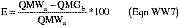
Where:
E = Destruction efficiency of Table 8 or Table 9 compounds for the combustion unit, percent.
QMWa = Mass flow rate of Table 8 or Table 9 compounds entering the combustion unit, kilograms per hour.
QMGb = Mass flow rate of Table 8 or Table 9 compounds in vented gas stream exiting the combustion treatment process, kilograms per hour.
(8) Calculation of flow-weighted average of Fr values. Use Equation WW8 to calculate the flow-weighted average of the Fr values listed in table 9 of this subpart.

Where:
Fravg = Flow-weighted average of the Fr values.
Ci, a, k = Concentration of Table 8 and/or Table 9 compounds in wastewater stream entering the combustion unit, during run k, parts per million by weight.
Qa, k = Volumetric flow rate of wastewater entering the combustion unit during run k, cubic meters per hour.
Fri = Compound-specific Fr value listed in table 9 of this subpart.
(9) Calculate flow-weighted average of Fr values and compare to mass destruction efficiency. Compare the mass destruction efficiency (calculated in Equation WW 7) to the required efficiency as specified in § 63.138(e). If complying with § 63.138(e)(1), compliance is demonstrated if the mass destruction efficiency is 99 percent or greater. If complying with § 63.138(e)(2), compliance is demonstrated if the mass destruction efficiency is greater than or equal to the flow-weighted average of the Fr value calculated in Equation WW8.
(e) Non-combustion treatment processes including closed biological treatment processes: RMR option. This paragraph applies to performance tests for non-combustion treatment processes other than open biological treatment processes to demonstrate compliance with the mass removal provisions for Table 8 and/or Table 9 compounds. Compliance options for noncombustion treatment processes are specified in § 63.138(f) of this subpart. Compliance options for closed aerobic or anaerobic biological treatment processes are specified in § 63.138(f) and § 63.138(g) of this subpart. When complying with § 63.138(f), the owner or operator shall comply with the requirements specified in § 63.145(e)(1) through (e)(6) of this subpart. When complying with § 63.138(g), the owner or operator shall comply with the requirements specified in § 63.145(e)(1) through (e)(6) of this subpart. (Wastewater streams that are Group 1 for both Table 8 and Table 9 compounds need only do the compliance demonstration for Table 9 compounds.)
(1) Concentration in wastewater stream. The concentration of Table 8 and/or Table 9 compounds shall be determined as provided in this paragraph. Concentration measurements to determine RMR shall be taken at the point of determination or downstream of the point of determination with adjustment for concentration change made according to § 63.144(b)(6) of this subpart. Concentration measurements to determine AMR shall be taken at the inlet and outlet to the treatment process and as provided in § 63.145(a)(7) for a series of treatment processes. Wastewater samples shall be collected using sampling procedures which minimize loss of organic compounds during sample collection and analysis and maintain sample integrity per § 63.144(b)(5)(ii). The method shall be an analytical method for wastewater which has that compound as a target analyte. Samples may be grab samples or composite samples. Samples shall be taken at approximately equally spaced time intervals over a 1-hour period. Each 1-hour period constitutes a run, and the performance test shall consist of a minimum of 3 runs. Concentration measurements based on Method 305 shall be adjusted by dividing each concentration by the compound-specific Fm factor listed in table 34 of this subpart. Concentration measurements based on methods other than Method 305 shall not adjust by the compound-specific Fm factor listed in table 34 of this subpart.
(2) Flow rate. Flow rate measurements to determine RMR shall be taken at the point of determination or downstream of the point of determination with adjustment for flow rate change made according to § 63.144(c)(4) of this subpart. Flow rate measurements to determine AMR shall be taken at the inlet and outlet to the treatment process and as provided in § 63.145(a)(7) for a series of treatment processes. Flow rate shall be determined using inlet and outlet flow measurement devices. Where the outlet flow is not greater than the inlet flow, a flow measurement device shall be used, and may be used at either the inlet or outlet. Flow rate measurements shall be taken at the same time as the concentration measurements.
(3) Calculation of RMR for non-combustion treatment processes including closed biological treatment processes. When using § 63.138(f) to comply, the required mass removal of Table 8 and/or Table 9 compounds for each Group 1 wastewater stream shall be calculated as specified in paragraph (e)(3)(i) of this section. When using § 63.138(g) to comply, the required mass removal shall be calculated as specified in paragraph (e)(3)(ii) of this section.
(i) When using § 63.138(f) to comply, the required mass removal of Table 8 and/or Table 9 compounds for each Group 1 wastewater stream shall be calculated using Equation WW9.

Where:
RMR = Required mass removal for treatment process or series of treatment processes, kilograms per hour.
ρ = Density of the Group 1 wastewater stream, kilograms per cubic meter.
Q = Volumetric flow rate of wastewater stream at the point of determination, liters per hour.
i = Identifier for a compound.
n = Number of Table 8 or Table 9 compounds in stream.
Ci = Concentration of Table 8 or Table 9 compounds at the point of determination, parts per million by weight.
Fri = Fraction removal value of a Table 8 or Table 9 compound. Fr values are listed in table 9 of this subpart.
109 = Conversion factor, mg/kg * l/m3.
(ii) When using § 63.138(g) to comply, the required mass removal is 95 percent of the mass flow rate for all Group 1 and Group 2 wastewater streams combined for treatment. The required mass removal of Table 8 and/or Table 9 compounds for all Group 1 and Group 2 wastewater streams combined for treatment when complying with § 63.138(g) shall be calculated using the following equation:

Where:
RMR = Required mass removal for treatment process or series of treatment processes, kilograms per hour.
ρ = Density of the Group 1 wastewater stream, kilograms per cubic meter.
Q = Volumetric flow rate of wastewater stream at the point of determination, liters per hour.
i = Identifier for a compound.
n = Number of Table 8 or Table 9 compounds in stream.
Ci = Concentration of Table 8 or Table 9 compounds at the point of determination, parts per million by weight.
109 = Conversion factor, mg/kg * l/m3
(4)
(i) The required mass removal is calculated by summing the required mass removal for each Group 1 wastewater stream to be combined for treatment when complying with § 63.138(f).
(ii) The required mass removal is calculated by summing the required mass removal for all Group 1 and Group 2 wastewater streams combined for treatment when complying with § 63.138(g).
(5) The AMR calculation procedure for non-combustion treatment processes including closed biological treatment processes. The AMR shall be calculated as follows:

Where:
AMR = Actual mass removal of Table 8 or Table 9 compounds achieved by treatment process or series of treatment processes, kilograms per hour.
QMWa = Mass flow rate of Table 8 or Table 9 compounds in wastewater entering the treatment process or first treament process in a series of treatment processes, kilograms per hour.
QMWb = Mass flow rate of Table 8 or Table 9 compounds in wastewater exiting the last treatment process in a series of treatment processes, kilograms per hour.
(6) Compare RMR to AMR. When complying with § 63.138(f), compare the RMR calculated in Equation WW9 to the AMR calculated in Equation WW10. Compliance is demonstrated if the AMR is greater than or equal to the RMR. When complying with § 63.138(g), compare the RMR calculated in Equation WW-9a to the AMR calculated in Equation WW10. Compliance is demonstrated if the AMR is greater than or equal to 95-percent mass removal.
(f) Open or closed aerobic biological treatment processes: Required mass removal (RMR) option. This paragraph applies to the use of performance tests that are conducted for open or closed aerobic biological treatment processes to demonstrate compliance with the mass removal provisions for Table 8 and/or Table 9 compounds. These compliance options are specified in § 63.138(f) of this subpart. The owner or operator shall comply with the requirements specified in § 63.145 (f)(1) through (f)(6) of this subpart. Some compounds may not require a performance test. Refer to § 63.145(h) and table 36 of this subpart to determine which compounds may be exempt from the requirements of this paragraph.
(1) Concentration in wastewater stream. The concentration of Table 8 and/or Table 9 compounds shall be determined as provided in this paragraph. Concentration measurements to determine RMR shall be taken at the point of determination or downstream of the point of determination with adjustment for concentration change made according to § 63.144(b)(6) of this subpart. Concentration measurements to determine AMR shall be taken at the inlet and outlet to the treatment process and as provided in § 63.145(a)(7) for a series of treatment processes. Wastewater samples shall be collected using sampling procedures which minimize loss of organic compounds during sample collection and analysis and maintain sample integrity per § 63.144(b)(5)(ii). The method shall be an analytical method for wastewater which has that compound as a target analyte. Samples may be grab samples or composite samples. Samples shall be taken at approximately equally spaced time intervals over a 1-hour period. Each 1-hour period constitutes a run, and the performance test shall consist of a minimum of 3 runs. Concentration measurements based on Method 305 shall be adjusted by dividing each concentration by the compound-specific Fm factor listed in table 34 of this subpart. Concentration measurements based on methods other than Method 305 shall not adjust by the compound-specific Fm factor listed in table 34 of this subpart.
(2) Flow rate. Flow rate measurements to determine RMR shall be taken at the point of determination or downstream of the point of determination with adjustment for flow rate change made according to § 63.144(c)(4) of this subpart. Flow rate measurements to determine AMR shall be taken at the inlet and outlet to the treatment process and as provided in § 63.145(a)(7) for a series of treatment processes. Flow rate shall be determined using inlet and outlet flow measurement devices. Where the outlet flow is not greater than the inlet flow, a flow measurement device shall be used, and may be used at either the inlet or outlet. Flow rate measurements shall be taken at the same time as the concentration measurements.
(3) Calculation of RMR for open or closed aerobic biological treatment processes. The required mass removal of Table 8 and/or Table 9 compounds for each Group 1 wastewater stream shall be calculated using the following equation:

Where:
RMR = Required mass removal for treatment process or series of treatment processes, kilograms per hour.
ρ = Density of the Group 1 wastewater stream, kilograms per cubic meter.
Q = Volumetric flow rate of wastewater stream at the point of determination, liters per hour.
i = Identifier for a compound.
n = Number of Table 8 or Table 9 compounds in stream.
Ci = Concentration of Table 8 or Table 9 compounds at the point of determination, parts per million by weight.
Fri = Fraction removal value of a Table 8 or Table 9 compound. Fr values are listed in table 9 of this subpart.
109 = Conversion factor, mg/kg * l/m3.
(4) The required mass removal is calculated by adding together the required mass removal for each Group 1 wastewater stream to be combined for treatment.
(5) Actual mass removal calculation procedure for open or closed aerobic biological treatment processes. The actual mass removal (AMR) shall be calculated using Equation WW12 as specified in paragraph (f)(5)(i) of this section when the performance test is performed across the open or closed aerobic biological treatment process only. If compliance is being demonstrated in accordance with § 63.145(a)(7)(i), the AMR for the series shall be calculated using Equation WW13 in § 63.145(f)(5)(ii). (This equation is for situations where treatment is performed in a series of treatment processes connected by hard-piping.) If compliance is being demonstrated in accordance with § 63.145(a)(7)(ii), the AMR for the biological treatment process shall be calculated using Equation WW12 in § 63.145(f)(5)(i). The AMR for the biological treatment process used in a series of treatment processes calculated using Equation WW12 shall be added to the AMR determined for each of the other individual treatment processes in the series of treatment processes.
(i) Calculate AMR for the open or closed aerobic biological treatment process as follows:

Where:
AMR = Actual mass removal of Table 8 or Table 9 compounds achieved by open or closed biological treatment process, kilograms per hour.
QMWa = Mass flow rate of Table 8 or Table 9 compounds in wastewater entering the treatment process, kilograms per hour.
Fbio = Site-specific fraction of Table 8 or Table 9 compounds biodegraded. Fbio shall be determined as specified in § 63.145(h) and appendix C of this subpart.
(ii) Calculate AMR across a series of treatment units where the last treatment unit is an open or closed aerobic biological treatment process as follows:

Where:
AMR = Actual mass removal of Table 8 or Table 9 compounds achieved by a series of treatment processes, kilograms per hour.
QMWa = Mass flow rate of Table 8 or Table 9 compounds in wastewater entering the first treatment process in a series of treatment processes, kilograms per hour.
QMWb = Mass flow rate of Table 8 or Table 9 compounds in wastewater exiting the last treatment process in a series of treatment processes prior to the biological treatment process, kilograms per hour.
Fbio = Site-specific fraction of Table 8 or Table 9 compounds biodegraded. Fbio shall be determined as specified in § 63.145(h) and appendix C of this subpart.
(6) Compare RMR to AMR. Compare the RMR calculated in Equation WW11 to the AMR calculated in either Equation WW12 or WW13, as applicable. Compliance is demonstrated if the AMR is greater than or equal to the RMR.
(g) Open or closed aerobic biological treatment processes: 95-percent mass removal option. This paragraph applies to performance tests that are conducted for open or closed aerobic biological treatment processes to demonstrate compliance with the 95-percent mass removal provisions for Table 8 and/or Table 9 compounds. This compliance option is specified in § 63.138(g) of this subpart. The RMR for this option is 95-percent mass removal. The owner or operator shall comply with the requirements specified in § 63.145(g)(1) to determine AMR, § 63.145 (e)(3)(ii) and (e)(4)(ii) to determine RMR, and (g)(2) of this subpart to determine whether compliance has been demonstrated. Some compounds may not require a performance test. Refer to § 63.145(h) and table 36 of this subpart to determine which compounds may be exempt from the requirements of this paragraph. (Wastewater streams that are Group 1 for both Table 8 and Table 9 compounds need only do the compliance demonstration for Table 9 compounds.)
(1) The owner or operator shall comply with the requirements specified in paragraphs (f)(1), (f)(2), and (f)(5) of this section to determine AMR. References to Group 1 wastewater streams shall be deemed Group 1 and Group 2 wastewater streams for the purposes of this paragraph.
(2) Compare RMR to AMR. Compliance is demonstrated if the AMR is greater than or equal to RMR.
(h) Site-specific fraction biodegraded (Fbio). The compounds listed in table 9 of this subpart are divided into two sets for the purpose of determining whether Fbio must be determined, and if Fbio must be determined, which procedures may be used to determine compound-specific kinetic parameters. These sets are designated as lists 1 and 2 in table 36 of this subpart.
(1) Performance test exemption. If a biological treatment process meets the requirements specified in paragraphs (h)(1)(i) and (h)(1)(ii) of this section, the owner or operator is not required to determine Fbio and is exempt from the applicable performance test requirements specified in § 63.138 of this subpart.
(i) The biological treatment process meets the definition of “enhanced biological treatment process” in § 63.111 of this subpart.
(ii) At least 99 percent by weight of all compounds on table 36 of this subpart that are present in the aggregate of all wastewater streams using the biological treatment process to comply with § 63.138 of this subpart are compounds on list 1 of table 36 of this subpart.
(2) Fbio determination. If a biological treatment process does not meet the requirement specified in paragraph (h)(1)(i) of this section, the owner or operator shall determine Fbio for the biological treatment process using the procedures in appendix C to part 63, and paragraph (h)(2)(ii) of this section. If a biological treatment process meets the requirements of paragraph (h)(1)(i) of this section but does not meet the requirement specified in paragraph (h)(1)(ii) of this section, the owner or operator shall determine Fbio for the biological treatment process using the procedures in appendix C to part 63, and paragraph (h)(2)(i) of this section.
(i) Enhanced biological treatment processes. If the biological treatment process meets the definition of “enhanced biological treatment process” in § 63.111 of this subpart and the wastewater streams include one or more compounds on list 2 of table 36 of this subpart that do not meet the criteria in paragraph (h)(1)(ii) of this section, the owner or operator shall determine fbio for the list 2 compounds using any of the procedures specified in appendix C of 40 CFR part 63. (The symbol “fbio” represents the site specific fraction of an individual Table 8 or Table 9 compound that is biodegraded.) The owner or operator shall calculate fbio for the list 1 compounds using the defaults for first order biodegradation rate constants (K1) in table 37 of subpart G and follow the procedure explained in form III of appendix C, 40 CFR part 63, or any of the procedures specified in appendix C, 40 CFR part 63.
(ii) Biological treatment processes that are not enhanced biological treatment processes. For biological treatment processes that do not meet the definition for “enhanced biological treatment process” in § 63.111 of this subpart, the owner or operator shall determine the fbio for the list 1 and 2 compounds using any of the procedures in appendix C to part 63, except procedure 3 (inlet and outlet concentration measurements). (The symbol “fbio” represents the site specific fraction of an individual Table 8 or Table 9 compound that is biodegraded.)
(i) Performance tests for control devices other than flares. This paragraph applies to performance tests that are conducted to demonstrate compliance of a control device with the efficiency limits specified in § 63.139(c). If complying with the 95-percent reduction efficiency requirement, comply with the requirements specified in paragraphs (i)(1) through (i)(9) of this section. If complying with the 20 ppm by volume requirement, comply with the requirements specified in paragraphs (i)(1) through (i)(6) and (i)(9) of this section. The 20 ppm by volume limit or 95-percent reduction efficiency requirement shall be measured as either total organic hazardous air pollutants or as TOC minus methane and ethane.
(1) Sampling sites. Sampling sites shall be selected using Method 1 or 1A of 40 CFR part 60, appendix A, as appropriate. For determination of compliance with the 95 percent reduction requirement, sampling sites shall be located at the inlet and the outlet of the control device. For determination of compliance with the 20 parts per million by volume limit, the sampling site shall be located at the outlet of the control device.
(2) Concentration in gas stream entering or exiting the control device. The concentration of total organic hazardous air pollutants or TOC in a gas stream shall be determined as provided in this paragraph. Samples may be grab samples or composite samples (i.e., integrated samples). Samples shall be taken at approximately equally spaced time intervals over a 1-hour period. Each 1-hour period constitutes a run, and the performance test shall consist of a minimum of 3 runs. Concentration measurements shall be determined using Method 18 of 40 CFR part 60, appendix A. Alternatively, any other test method validated according to the procedures in Method 301 of appendix A of this part may be used.
(3) Volumetric flow rate of gas stream entering or exiting the control device. The volumetric flow rate of the gas stream shall be determined using Method 2, 2A, 2C, or 2D of 40 CFR part 60, appendix A, as appropriate. Volumetric flow rate measurements shall be taken at the same time as the concentration measurements.
(4) Calculation of TOC concentration. The TOC concentration (CGT) is the sum of the concentrations of the individual components. If compliance is being determined based on TOC, the owner or operator shall compute TOC for each run using the following equation:

Where:
CGT = Total concentration of TOC (minus methane and ethane) in vented gas stream, average of samples, dry basis, parts per million by volume.
CGSi j = Concentration of sample components in vented gas stream for sample j, dry basis, parts per million by volume.
i = Identifier for a compound.
n = Number of components in the sample.
j = Identifier for a sample.
m = Number of samples in the sample run.
(5) Calculation of total organic hazardous air pollutants concentration. The owner or operator determining compliance based on total organic hazardous air pollutants concentration (CHAP) shall compute CHAP according to the Equation WW14, except that only Table 9 compounds shall be summed.
(6) Percent oxygen correction for combustion control devices. If the control device is a combustion device, comply with the requirements specified in paragraph (i)(6)(i) of this section to determine oxygen concentration, and in paragraph (i)(6)(ii) of this section to calculate the percent oxygen correction.
(i) Oxygen concentration. The concentration of TOC or total organic hazardous air pollutants shall be corrected to 3 percent oxygen if the control device is a combustion device. The emission rate correction factor for excess air, composite sampling (i.e., integrated sampling) and analysis procedures of Method 3B of 40 CFR part 60, appendix A shall be used to determine the actual oxygen concentration (%02d). The samples shall be taken during the same time that the TOC (minus methane or ethane) or total organic hazardous air pollutants samples are taken.
(ii) 3 percent oxygen calculation. The concentration corrected to 3 percent oxygen (CGc), when required, shall be computed using the following equation:

Where:
CGc = Concentration of TOC or organic hazardous air pollutants corrected to 3 percent oxygen, dry basis, parts per million by volume.
CGT = Total concentration of TOC (minus methane and ethane) in vented gas stream, average of samples, dry basis, parts per million by volume.
%02d = Concentration of oxygen measured in vented gas stream, dry basis, percent by volume.
(7) Mass rate calculation. The mass rate of either TOC (minus methane and ethane) or total organic hazardous air pollutants shall be calculated using the following equations. Where the mass rate of TOC is being calculated, all organic compounds (minus methane and ethane) measured by methods specified in paragraph (i)(2) of this section are summed using Equations WW16 and WW17. Where the mass rate of total organic hazardous air pollutants is being calculated, only Table 9 compounds shall be summed using Equations WW16 and WW17.


Where:
CGa, i, CGb, i = Concentration of TOC (minus methane and ethane) or total organic hazardous air pollutants, in vented gas stream, entering (CGa, i) and exiting (CGb, i) the control device, dry basis, parts per million by volume.
QMGa, QMGb = Mass rate of TOC (minus methane and ethane) or total organic hazardous air pollutants, in vented gas stream, entering (QMGa) and exiting (QMGb) the control device, dry basis, kilograms per hour.
MWi = Molecular weight of a component, kilogram/kilogram-mole.
QGa, QGb = Flow rate of gas stream entering (QGa) and exiting (QGb) the control device, dry standard cubic meters per hour.
K2 = Constant, 41.57 × 10⁻⁹ (parts per million)−1 (gram-mole per standard cubic meter) (kilogram/gram), where standard temperature (gram-mole per standard cubic meter) is 20 °Celsius.
i = Identifier for a compound.
n = Number of components in the sample.
(8) Percent reduction calculation. The percent reduction in TOC (minus methane and ethane) or total organic hazardous air pollutants shall be calculated as follows:

Where:
E = Destruction efficiency of control device, percent.
QMGa, QMGb = Mass rate of TOC (minus methane and ethane) or total organic hazardous air pollutants, in vented gas stream entering and exiting (QMGb) the control device, dry basis, kilograms per hour.
(9) Compare mass destruction efficiency to required efficiency. If complying with the 95 percent reduction efficiency requirement, compliance is demonstrated if the mass destruction efficiency (calculated in Equation WW18) is 95 percent or greater. If complying with the 20 parts per million by volume limit in § 63.139 (c)(1)(ii) of this subpart, compliance is demonstrated if the outlet total organic compound concentration, less methane and ethane, or total organic hazardous air pollutants concentration is 20 parts per million by volume, or less. For combustion control devices, the concentration shall be calculated on a dry basis, corrected to 3 percent oxygen.
(j) When a flare is used to comply with § 63.139(c), the owner or operator shall comply with paragraphs (j)(1) through (3) of this section. The owner or operator is not required to conduct a performance test to determine percent emission reduction or outlet organic HAP or TOC concentration.
(1) Conduct a visible emission test using the techniques specified in § 63.11(b)(4).
(2) Determine the net heating value of the gas being combusted using the techniques specified in § 63.11(b)(6).
(3) Determine the exit velocity using the techniques specified in either § 63.11(b)(7)(i) (and § 63.11(b)(7)(iii), where applicable) or § 63.11(b)(8), as appropriate.
[62 FR 2765, Jan. 17, 1997, as amended at 63 FR 67793, Dec. 9, 1998; 64 FR 20192, Apr. 26, 1999; 66 FR 6933, Jan. 22, 2001]
§ 63.146 Process wastewater provisions—reporting.
(a) For each waste management unit, treatment process, or control device used to comply with §§ 63.138 (b)(1), (c)(1), (d), (e), (f), or (g) of this subpart for which the owner or operator seeks to monitor a parameter other than those specified in table 11, table 12, or table 13 of this subpart, the owner or operator shall submit a request for approval to monitor alternative parameters according to the procedures specified in § 63.151(f) or (g) of this subpart.
(b) The owner or operator shall submit the information specified in paragraphs (b)(1) through (b)(9) of this section as part of the Notification of Compliance Status required by § 63.152(b) of this subpart.
(1) Requirements for Group 2 wastewater streams. This paragraph does not apply to Group 2 wastewater streams that are used to comply with § 63.138(g). For Group 2 wastewater streams, the owner or operator shall include the information specified in paragraphs (b)(1)(i) through (iv) of this section in the Notification of Compliance Status Report. This information may be submitted in any form. Table 15 of this subpart is an example.
(i) Process unit identification and description of the process unit.
(ii) Stream identification code.
(iii) For existing sources, concentration of table 9 compound(s) in parts per million, by weight. For new sources, concentration of table 8 and/or table 9 compound(s) in parts per million, by weight. Include documentation of the methodology used to determine concentration.
(iv) Flow rate in liter per minute.
(2) For each new and existing source, the owner or operator shall submit the information specified in table 15 of this subpart for Table 8 and/or Table 9 compounds.
(3) [Reserved]
(4) For each treatment process identified in table 15 of this subpart that receives, manages, or treats a Group 1 wastewater stream or residual removed from a Group 1 wastewater stream, the owner or operator shall submit the information specified in table 17 of this subpart.
(5) For each waste management unit identified in table 15 of this subpart that receives or manages a Group 1 wastewater stream or residual removed from a Group 1 wastewater stream, the owner or operator shall submit the information specified in table 18 of this subpart.
(6) For each residual removed from a Group 1 wastewater stream, the owner or operator shall report the information specified in table 19 of this subpart.
(7) For each control device used to comply with §§ 63.133 through 63.139 of this subpart, the owner or operator shall report the information specified in paragraphs (b)(7)(i) and (b)(7)(ii) of this section.
(i) For each flare, the owner or operator shall submit the information specified in paragraphs (b)(7)(i)(A) through (b)(7)(i)(C) of this section.
(A) Flare design (i.e., steam-assisted, air-assisted, or non-assisted);
(B) All visible emission readings, heat content determinations, flow rate measurements, and exit velocity determinations made during the compliance determination required by § 63.139(c)(3) of this subpart; and
(C) Reports of the times and durations of all periods during the compliance determination when the pilot flame is absent or the monitor is not operating.
(ii) For each control device other than a flare, the owner or operator shall submit the information specified in paragraph (b)(7)(ii)(A) of this section and in either paragraph (b)(7)(ii)(B) or (b)(7)(ii)(C) of this section.
(A) The information on parameter ranges specified in § 63.152(b)(2) of this subpart for the applicable parameters specified in table 13 of this subpart, unless the parameter range has already been established in the operating permit; and either
(B) The design evaluation specified in § 63.139(d)(2) of this subpart; or
(C) Results of the performance test specified in § 63.139(d)(1) of this subpart. Performance test results shall include operating ranges of key process and control parameters during the performance test; the value of each parameter being monitored in accordance with § 63.143 of this subpart; and applicable supporting calculations.
(8) For each treatment process used to comply with § 63.138(b)(1), (c)(1), (d), (e), (f), or (g) of this subpart, the owner or operator shall submit the information specified in paragraphs (b)(8)(i) and (b)(8)(ii) of this section.
(i) For Items 1 and 2 in table 12 of this subpart, the owner or operator shall submit the information specified in paragraphs (b)(8)(i)(A) and (b)(8)(i)(B) of this section. An owner or operator using the design steam stripper compliance option specified § 63.138(d) of this subpart does not have to submit the information specified in paragraph (b)(8)(i)(A) or (b)(8)(i)(B) of this section. However, the monitoring requirements specified in Item 2 of table 12 of this subpart still apply.
(A) The information on parameter ranges specified in § 63.152(b)(2) of this subpart for the parameters approved by the Administrator, unless the parameter range has already been established in the operating permit.
(B) Results of the initial measurements of the parameters approved by the Administrator and any applicable supporting calculations.
(ii) For Item 3 in table 12 of this subpart, the owner or operator shall submit the information on parameter ranges specified in § 63.152(b)(2) of this subpart for the parameters specified in Item 3 of table 12 of this subpart, unless the parameter range has already been established in the operating permit.
(9) For each waste management unit or treatment process used to comply with § 63.138(b)(1), (c)(1), (e), (f), or (g), the owner or operator shall submit the information specified in either paragraph (b)(9)(i) or (ii) of this section.
(i) The design evaluation and supporting documentation specified in § 63.138(j)(1) of this subpart.
(ii) Results of the performance test specified in § 63.138(j)(2) of this subpart. Performance test results shall include operating ranges of key process and control parameters during the performance test; the value of each parameter being monitored in accordance with § 63.143 of this subpart; and applicable supporting calculations.
(c) For each waste management unit that receives, manages, or treats a Group 1 wastewater stream or residual removed from a Group 1 wastewater stream, the owner or operator shall submit as part of the next Periodic Report required by § 63.152(c) of this subpart the results of each inspection required by § 63.143(a) of this subpart in which a control equipment failure was identified. Control equipment failure is defined for each waste management unit in §§ 63.133 through 63.137 of this subpart. Each Periodic Report shall include the date of the inspection, identification of each waste management unit in which a control equipment failure was detected, description of the failure, and description of the nature of and date the repair was made.
(d) Except as provided in paragraph (f) of this section, for each treatment process used to comply with § 63.138(b)(1), (c)(1), (d), (e) , (f), or (g), the owner or operator shall submit as part of the next Periodic Report required by § 63.152(c) the information specified in paragraphs (d)(1), (2), and (3) of this section for the monitoring required by § 63.143(b), (c), and (d).
(1) For Item 1 in table 12, the owner or operator shall submit the results of measurements that indicate that the biological treatment unit is outside the range established in the Notification of Compliance Status or operating permit.
(2) For Item 2 in table 12, the owner or operator shall submit the monitoring results for each operating day during which the daily average value of a continuously monitored parameter is outside the range established in the Notification of Compliance Status or operating permit.
(3) For Item 3 in table 12 of this subpart, the owner or operator shall submit the monitoring results for each operating day during which the daily average value of any monitored parameter approved in accordance with § 63.151 (f) was outside the range established in the Notification of Compliance Status or operating permit.
(e) Except as provided in paragraph (f) of this section, for each control device used to comply with §§ 63.133 through 63.139 of this subpart, the owner or operator shall submit as part of the next Periodic Report required by § 63.152(c) of this subpart the information specified in either paragraph (e)(1) or (e)(2) of this section.
(1) The information specified in table 20 of this subpart, or
(2) If the owner or operator elects to comply with § 63.143(e)(2) of this subpart, i.e., an organic monitoring device installed at the outlet of the control device, the owner or operator shall submit the monitoring results for each operating day during which the daily average concentration level or reading is outside the range established in the Notification of Compliance Status or operating permit.
(f) Where the owner or operator obtains approval to use a treatment process or control device other than one for which monitoring requirements are specified in § 63.143 of this subpart, or to monitor parameters other than those specified in table 12 or 13 of this subpart, the Administrator will specify appropriate reporting requirements.
(g) If an extension is utilized in accordance with § 63.133(e)(2) or § 63.133(h) of this subpart, the owner or operator shall include in the next periodic report the information specified in § 63.133 (e)(2) or § 63.133(h).
[62 FR 2774, Jan. 17, 1997, as amended at 64 FR 20192, Apr. 26, 1999; 66 FR 6933, Jan. 22, 2001]
§ 63.147 Process wastewater provisions—recordkeeping.
(a) The owner or operator transferring a Group 1 wastewater stream or residual removed from a Group 1 wastewater stream in accordance with § 63.132(g) of this subpart shall keep a record of the notice sent to the treatment operator stating that the wastewater stream or residual contains organic hazardous air pollutants which are required to be managed and treated in accordance with the provisions of this subpart.
(b) The owner or operator shall keep in a readily accessible location the records specified in paragraphs (b)(1) through (8) of the section.
(1) A record that each waste management unit inspection required by §§ 63.133 through 63.137 of this subpart was performed.
(2) A record that each inspection for control devices required by § 63.139 of this subpart was performed.
(3) A record of the results of each seal gap measurement required by §§ 63.133(d) and 63.137(c) of this subpart. The records shall include the date of the measurement, the raw data obtained in the measurement, and the calculations described in § 63.120(b)(2), (3), and (4) of this subpart.
(4) For Item 1 and Item 3 of table 12 of this subpart, the owner or operator shall keep the records approved by the Administrator.
(5) Except as provided in paragraph (e) of this section, continuous records of the monitored parameters specified in Item 2 of table 12 and table 13 of this subpart, and in § 63.143(e)(2) of this subpart.
(6) Documentation of a decision to use an extension, as specified in § 63.133(e)(2) or (h) of this subpart, which shall include a description of the failure, documentation that alternate storage capacity is unavailable, and specification of a schedule of actions that will ensure that the control equipment will be repaired or the vessel will be emptied as soon as practical.
(7) Documentation of a decision to use a delay of repair due to unavailability of parts, as specified in § 63.140(c), shall include a description of the failure, the reason additional time was necessary (including a statement of why replacement parts were not kept on site and when the manufacturer promised delivery), and the date when repair was completed.
(8) Requirements for Group 2 wastewater streams. This paragraph (b)(8) does not apply to Group 2 wastewater streams that are used to comply with § 63.138(g). For all other Group 2 wastewater streams, the owner or operator shall keep in a readily accessible location the records specified in paragraphs (b)(8)(i) through (iv) of this section.
(i) Process unit identification and description of the process unit.
(ii) Stream identification code.
(iii) For existing sources, concentration of table 9 compound(s) in parts per million, by weight. For new sources, concentration of table 8 and/or table 9 compound(s) in parts per million, by weight. Include documentation of the methodology used to determine concentration.
(iv) Flow rate in liter per minute.
(c) For each boiler or process heater used to comply with §§ 63.133 through 63.139 of this subpart, the owner or operator shall keep a record of any changes in the location at which the vent stream is introduced into the flame zone as required in § 63.139(c)(1) of this subpart.
(d) The owner or operator shall keep records of the daily average value of each continuously monitored parameter for each operating day as specified in § 63.152(f), except as provided in paragraphs (d)(1) through (3) of this section.
(1) For flares, records of the times and duration of all periods during which the pilot flame is absent shall be kept rather than daily averages.
(2) Regenerative carbon adsorbers. For regenerative carbon adsorbers, the owner or operator shall keep the records specified in paragraphs (d)(2)(i) and (ii) of this section instead of daily averages.
(i) Records of the total regeneration stream mass flow for each carbon bed regeneration cycle.
(ii) Records of the temperature of the carbon bed after each regeneration cycle.
(3) Non-regenerative carbon adsorbers. For non-regenerative carbon adsorbers using organic monitoring equipment, the owner or operator shall keep the records specified in paragraph (d)(3)(i) of this section instead of daily averages. For non-regenerative carbon adsorbers replacing the carbon adsorption system with fresh carbon at a regular predetermined time interval that is less than the carbon replacement interval that is determined by the maximum design flow rate and organic concentration in the gas stream vented to the carbon adsorption system, the owner or operator shall keep the records specified in paragraph (d)(3)(ii) of this section instead of daily averages.
(i)
(A) Record of how the monitoring frequency, as specified in table 13 of this subpart, was determined.
(B) Records of when organic compound concentration of adsorber exhaust was monitored.
(C) Records of when the carbon was replaced.
(ii)
(A) Record of how the carbon replacement interval, as specified in table 13 of this subpart, was determined.
(B) Records of when the carbon was replaced.
(e) Where the owner or operator obtains approval to use a control device other than one for which monitoring requirements are specified in § 63.143 of this subpart, or to monitor parameters other than those specified in table 12 or table 13 of this subpart, the Administrator will specify appropriate recordkeeping requirements.
(f) If the owner or operator uses process knowledge to determine the annual average concentration of a wastewater stream as specified in § 63.144(b)(3) of this subpart and/or uses process knowledge to determine the annual average flow rate as specified in § 63.144(c)(1) of this subpart, and determines that the wastewater stream is not a Group 1 wastewater stream, the owner or operator shall keep in a readily accessible location the documentation of how process knowledge was used to determine the annual average concentration and/or the annual average flow rate of the wastewater stream.
[62 FR 2775, Jan. 17, 1997, as amended at 64 FR 20192, Apr. 26, 1999; 66 FR 6933, Jan. 22, 2001]
§ 63.148 Leak inspection provisions.
(a) Except as provided in paragraph (k) of this section, for each vapor collection system, closed-vent system, fixed roof, cover, or enclosure required to comply with this section, the owner or operator shall comply with the requirements of paragraphs (b) through (j) of this section.
(b) Except as provided in paragraphs (g) and (h) of this section, each vapor collection system and closed-vent system shall be inspected according to the procedures and schedule specified in paragraphs (b)(1) and (b)(2) of this section and each fixed roof, cover, and enclosure shall be inspected according to the procedures and schedule specified in paragraph (b)(3) of this section.
(1) If the vapor collection system or closed vent system is constructed of hard-piping, the owner or operator shall:
(i) Conduct an initial inspection according to the procedures in paragraph (c) of this section, and
(ii) Conduct annual visual inspections for visible, audible, or olfactory indications of leaks.
(2) If the vapor collection system or closed vent system is constructed of ductwork, the owner or operator shall:
(i) Conduct an initial inspection according to the procedures in paragraph (c) of this section, and
(ii) Conduct annual inspections according to the procedures in paragraph (c) of this section.
(iii) Conduct annual visual inspections for visible, audible, or olfactory indications of leaks.
(3) For each fixed roof, cover, and enclosure, the owner or operator shall conduct initial visual inspections and semi-annual visual inspections for visible, audible, or olfactory indications of leaks as specified in §§ 63.133 through 63.137 of this subpart.
(c) Each vapor collection system and closed vent system shall be inspected according to the procedures specified in paragraphs (c)(1) through (c)(5) of this section.
(1) Inspections shall be conducted in accordance with Method 21 of 40 CFR part 60, appendix A.
(2)
(i) Except as provided in paragraph (c)(2)(ii) of this section, the detection instrument shall meet the performance criteria of Method 21 of 40 CFR part 60, appendix A, except the instrument response factor criteria in section 3.1.2(a) of Method 21 shall be for the average composition of the process fluid not each individual volatile organic compound in the stream. For process streams that contain nitrogen, air, or other inerts which are not organic hazardous air pollutants or volatile organic compounds, the average stream response factor shall be calculated on an inert-free basis.
(ii) If no instrument is available at the plant site that will meet the performance criteria specified in paragraph (c)(2)(i) of this section, the instrument readings may be adjusted by multiplying by the average response factor of the process fluid, calculated on an inert-free basis as described in paragraph (c)(2)(i) of this section.
(3) The detection instrument shall be calibrated before use on each day of its use by the procedures specified in Method 21 of 40 CFR part 60, appendix A.
(4) Calibration gases shall be as follows:
(i) Zero air (less than 10 parts per million hydrocarbon in air); and
(ii) Mixtures of methane in air at a concentration less than 10,000 parts per million. A calibration gas other than methane in air may be used if the instrument does not respond to methane or if the instrument does not meet the performance criteria specified in paragraph (c)(2)(i) of this section. In such cases, the calibration gas may be a mixture of one or more of the compounds to be measured in air.
(5) An owner or operator may elect to adjust or not adjust instrument readings for background. If an owner or operator elects to not adjust readings for background, all such instrument readings shall be compared directly to the applicable leak definition to determine whether there is a leak. If an owner or operator elects to adjust instrument readings for background, the owner or operator shall measure background concentration using the procedures in §§ 63.180(b) and (c) of subpart H of this part. The owner or operator shall subtract background reading from the maximum concentration indicated by the instrument.
(6) The arithmetic difference between the maximum concentration indicated by the instrument and the background level shall be compared with 500 parts per million for determining compliance.
(d) Leaks, as indicated by an instrument reading greater than 500 parts per million above background or by visual inspections, shall be repaired as soon as practicable, except as provided in paragraph (e) of this section.
(1) A first attempt at repair shall be made no later than 5 calendar days after the leak is detected.
(2) Repair shall be completed no later than 15 calendar days after the leak is detected, except as provided in paragraph (d)(3) of this section.
(3) For leaks found in vapor collection systems used for transfer operations, repairs shall be completed no later than 15 calendar days after the leak is detected or at the beginning of the next transfer loading operation, whichever is later.
(e) Delay of repair of a vapor collection system, closed vent system, fixed roof, cover, or enclosure for which leaks have been detected is allowed if the repair is technically infeasible without a shutdown, as defined in § 63.101 of subpart F of this part, or if the owner or operator determines that emissions resulting from immediate repair would be greater than the fugitive emissions likely to result from delay of repair. Repair of such equipment shall be complete by the end of the next shutdown.
(f) For each vapor collection system or closed vent system that contains bypass lines that could divert a vent stream away from the control device and to the atmosphere, the owner or operator shall comply with the provisions of either paragraph (f)(1) or (f)(2) of this section, except as provided in paragraph (f)(3) of this section.
(1) Install, calibrate, maintain, and operate a flow indicator that determines whether vent stream flow is present at least once every 15 minutes. Records shall be generated as specified in § 63.118(a)(3) of this subpart. The flow indicator shall be installed at the entrance to any bypass line; or
(2) Secure the bypass line valve in the closed position with a car-seal or a lock-and-key type configuration. A visual inspection of the seal or closure mechanism shall be performed at least once every month to ensure the valve is maintained in the closed position and the vent stream is not diverted through the bypass line.
(3) Equipment such as low leg drains, high point bleeds, analyzer vents, open-ended valves or lines, and pressure relief valves needed for safety purposes are not subject to this paragraph.
(g) Any parts of the vapor collection system, closed vent system, fixed roof, cover, or enclosure that are designated, as described in paragraph (i)(1) of this section, as unsafe to inspect are exempt from the inspection requirements of paragraphs (b)(1), (b)(2), and (b)(3)(i) of this section if:
(1) The owner or operator determines that the equipment is unsafe to inspect because inspecting personnel would be exposed to an imminent or potential danger as a consequence of complying with paragraphs (b)(1), (b)(2), or (b)(3)(i) of this section; and
(2) The owner or operator has a written plan that requires inspection of the equipment as frequently as practicable during safe-to-inspect times.
(h) Any parts of the vapor collection system, closed vent system, fixed roof, cover, or enclosure that are designated, as described in paragraph (i)(2) of this section, as difficult to inspect are exempt from the inspection requirements of paragraphs (b)(1), (b)(2), and (b)(3)(i) of this section if:
(1) The owner or operator determines that the equipment cannot be inspected without elevating the inspecting personnel more than 2 meters above a support surface; and
(2) The owner or operator has a written plan that requires inspection of the equipment at least once every 5 years.
(i) The owner or operator shall record the information specified in paragraphs (i)(1) through (i)(5) of this section.
(1) Identification of all parts of the vapor collection system, closed vent system, fixed roof, cover, or enclosure that are designated as unsafe to inspect, an explanation of why the equipment is unsafe to inspect, and the plan for inspecting the equipment.
(2) Identification of all parts of the vapor collection system, closed vent system, fixed roof, cover, or enclosure that are designated as difficult to inspect, an explanation of why the equipment is difficult to inspect, and the plan for inspecting the equipment.
(3) For each vapor collection system or closed vent system that contains bypass lines that could divert a vent stream away from the control device and to the atmosphere, the owner or operator shall keep a record of the information specified in either paragraph (i)(3)(i) or (i)(3)(ii) of this section.
(i) Hourly records of whether the flow indicator specified under paragraph (f)(1) of this section was operating and whether a diversion was detected at any time during the hour, as well as records of the times of all periods when the vent stream is diverted from the control device or the flow indicator is not operating.
(ii) Where a seal mechanism is used to comply with paragraph (f)(2) of this section, hourly records of flow are not required. In such cases, the owner or operator shall record whether the monthly visual inspection of the seals or closure mechanisms has been done, and shall record the occurrence of all periods when the seal mechanism is broken, the bypass line valve position has changed, or the key for a lock-and-key type configuration has been checked out, and records of any car-seal that has broken.
(4) For each inspection during which a leak is detected, a record of the information specified in paragraphs (i)(4)(i) through (i)(4)(viii) of this section.
(i) The instrument identification numbers; operator name or initials; and identification of the equipment.
(ii) The date the leak was detected and the date of the first attempt to repair the leak.
(iii) Maximum instrument reading measured by the method specified in paragraph (d) of this section after the leak is successfully repaired or determined to be nonrepairable.
(iv) “Repair delayed” and the reason for the delay if a leak is not repaired within 15 calendar days after discovery of the leak.
(v) The name, initials, or other form of identification of the owner or operator (or designee) whose decision it was that repair could not be effected without a shutdown.
(vi) The expected date of successful repair of the leak if a leak is not repaired within 15 calendar days.
(vii) Dates of shutdowns that occur while the equipment is unrepaired.
(viii) The date of successful repair of the leak.
(5) For each inspection conducted in accordance with paragraph (c) of this section during which no leaks are detected, a record that the inspection was performed, the date of the inspection, and a statement that no leaks were detected.
(6) For each visual inspection conducted in accordance with paragraph (b)(1)(ii) or (b)(3)(ii) of this section during which no leaks are detected, a record that the inspection was performed, the date of the inspection, and a statement that no leaks were detected.
(j) The owner or operator shall submit with the reports required by § 63.182(b) of subpart H of this part or with the reports required by § 63.152(c) of this subpart, the information specified in paragraphs (j)(1) through (j)(3) of this section.
(1) The information specified in paragraph (i)(4) of this section;
(2) Reports of the times of all periods recorded under paragraph (i)(3)(i) of this section when the vent stream is diverted from the control device through a bypass line; and
(3) Reports of all periods recorded under paragraph (i)(3)(ii) of this section in which the seal mechanism is broken, the bypass line valve position has changed, or the key to unlock the bypass line valve was checked out.
(k) If a closed-vent system subject to this section is also subject to § 63.172 of subpart H of this part, the owner or operator shall comply with the provisions of § 63.172 of subpart H of this part and is exempt from the requirements of this section.
[59 FR 19468, Apr. 22, 1994, as amended at 60 FR 63628, Dec. 12, 1995; 62 FR 2775, Jan. 17, 1997; 64 FR 20192, Apr. 26, 1999]
§ 63.149 Control requirements for certain liquid streams in open systems within a chemical manufacturing process unit.
(a) The owner or operator shall comply with the provisions of table 35 of this subpart, for each item of equipment meeting all the criteria specified in paragraphs (b) through (d) and either paragraph (e)(1) or (e)(2) of this section.
(b) The item of equipment is of a type identified in table 35 of this subpart;
(c) The item of equipment is part of a chemical manufacturing process unit that meets the criteria of § 63.100(b) of subpart F of this part;
(d) The item of equipment is controlled less stringently than in table 35 and is not listed in § 63.100(f) of subpart F of this part, and the item of equipment is not otherwise exempt from controls by the provisions of subparts A, F, G, or H of this part; and
(e) The item of equipment:
(1) is a drain, drain hub, manhole, lift station, trench, pipe, or oil/water separator that conveys water with a total annual average concentration greater than or equal to 10,000 parts per million by weight of Table 9 compounds at any flowrate; or a total annual average concentration greater than or equal to 1,000 parts per million by weight of Table 9 compounds at an annual average flow rate greater than or equal to 10 liters per minute. At a chemical manufacturing process unit subject to the new source requirements of 40 CFR 63.100(l)(1) or 40 CFR 63.100(l)(2), the criteria of this paragraph are also met if the item of equipment conveys water with an annual average concentration greater than or equal to 10 parts per million by weight of any Table 8 compound at an annual average flow rate greater than or equal to 0.02 liter per minute, or
(2) Is a tank that receives one or more streams that contain water with a total annual average concentration greater than or equal to 1,000 ppm (by weight) of Table 9 compounds at an annual average flowrate greater than or equal to 10 liters per minute. At a chemical manufacturing process unit subject to the new source requirements of 40 CFR 63.100(l)(1) or 40 CFR 63.100 (l)(2), the criteria of this paragraph are also met if the tank receives one or more streams that contain water with an annual average concentration greater than or equal to 10 parts per million by weight of any Table 8 compound at an annual average flow rate greater than or equal to 0.02 liter per minute. The owner or operator of the source shall determine the characteristics of the stream as specified in paragraphs (e)(2) (i) and (ii) of this section.
(i) The characteristics of the stream being received shall be determined at the inlet to the tank.
(ii) The characteristics shall be determined according to the procedures in § 63.144 (b) and (c).
[62 FR 2776, Jan. 17, 1997]
§ 63.150 Emissions averaging provisions.
(a) This section applies to owners or operators of existing sources who seek to comply with the emission standard in § 63.112(a) of this subpart by using emissions averaging according to § 63.112(f) of this subpart rather than following the provisions of §§ 63.113 through 63.148 of this subpart. Notwithstanding the definition of process vent in § 63.101 and the sampling site designation in § 63.115(a), for purposes of this section the location of a process vent shall be defined, and the characteristics of its gas stream shall be determined, consistent with paragraph (g)(2)(i) of this section.
(b) Unless an operating permit application has been submitted, the owner or operator shall develop and submit for approval an Implementation Plan containing all of the information required in § 63.151(d) of this subpart for all points to be included in an emissions average. The Implementation Plan or operating permit application shall identify all emission points to be included in the emissions average. This must include any Group 1 emission points to which the reference control technology (defined in § 63.111 of this subpart) is not applied and all other emission points being controlled as part of the average.
(c) The following emission points can be used to generate emissions averaging credits, if control was applied after November 15, 1990 and if sufficient information is available to determine the appropriate value of credits for the emission point:
(1) Group 2 emission points.
(2) Group 1 emission points that are controlled by a technology that the Administrator or permitting authority agrees has a higher nominal efficiency than the reference control technology. Information on the nominal efficiencies for such technologies must be submitted and approved as provided in paragraph (i) of this section.
(3) Emission points from which emissions are reduced by pollution prevention measures. Percent reductions for pollution prevention measures shall be determined as specified in paragraph (j) of this section.
(i) For a Group 1 emission point, the pollution prevention measure must reduce emissions more than the reference control technology would have had the reference control technology been applied to the emission point instead of the pollution prevention measure except as provided in paragraph (c)(3)(ii) of this section.
(ii) If a pollution prevention measure is used in conjunction with other controls for a Group 1 emission point, the pollution prevention measure alone does not have to reduce emissions more than the reference control technology, but the combination of the pollution prevention measure and other controls must reduce emissions more than the reference control technology would have had it been applied instead.
(d) The following emission points cannot be used to generate emissions averaging credits:
(1) Emission points already controlled on or before November 15, 1990, unless the level of control is increased after November 15, 1990, in which case credit will be allowed only for the increase in control after November 15, 1990.
(2) Group 1 emission points that are controlled by a reference control technology, unless the reference control technology has been approved for use in a different manner and a higher nominal efficiency has been assigned according to the procedures in paragraph (i) of this section. For example, it is not allowable to claim that an internal floating roof meeting the specifications of § 63.119(b) of this subpart applied to a storage vessel is achieving greater than 95 percent control.
(3) Emission points on shut-down process units. Process units that are shut down cannot be used to generate credits or debits.
(4) Wastewater that is not process wastewater or wastewater streams treated in biological treatment units. These two types of wastewater cannot be used to generate credits or debits. For the purposes of this section, the terms wastewater and wastewater stream are used to mean process wastewater.
(5) Emission points controlled to comply with a State or Federal rule other than this subpart, unless the level of control has been increased after November 15, 1990 above what is required by the other State or Federal rule. Only the control above what is required by the other State or Federal rule will be credited. However, if an emission point has been used to generate emissions averaging credit in an approved emissions average, and the point is subsequently made subject to a State or Federal rule other than this subpart, the point can continue to generate emissions averaging credit for the purpose of complying with the previously approved average.
(e) For all points included in an emissions average, the owner or operator shall:
(1) Calculate and record monthly debits for all Group 1 emission points that are controlled to a level less stringent than the reference control technology for those emission points. Equations in paragraph (g) of this section shall be used to calculate debits.
(2) Calculate and record monthly credits for all Group 1 or Group 2 emission points that are overcontrolled to compensate for the debits. Equations in paragraph (h) of this section shall be used to calculate credits. Emission points and controls that meet the criteria of paragraph (c) of this section may be included in the credit calculation, whereas those described in paragraph (d) of this section shall not be included.
(3) Demonstrate that annual credits calculated according to paragraph (h) of this section are greater than or equal to debits calculated for the same annual compliance period according to paragraph (g) of this section.
(i) The owner or operator may choose to include more than the required number of credit-generating emission points in an average in order to increase the likelihood of being in compliance.
(ii) The initial demonstration in the Implementation Plan or operating permit application that credit-generating emission points will be capable of generating sufficient credits to offset the debits from the debit-generating emission points must be made under representative operating conditions. After the compliance date, actual operating data will be used for all debit and credit calculations.
(4) Demonstrate that debits calculated for a quarterly (3-month) period according to paragraph (g) of this section are not more than 1.30 times the credits for the same period calculated according to paragraph (h) of this section. Compliance for the quarter shall be determined based on the ratio of credits and debits from that quarter, with 30 percent more debits than credits allowed on a quarterly basis.
(5) Record and report quarterly and annual credits and debits in the Periodic Reports as specified in § 63.152(c) of this subpart. Every fourth Periodic Report shall include a certification of compliance with the emissions averaging provisions as required by § 63.152(c)(5)(iv)(B) of this subpart.
(f) Debits and credits shall be calculated in accordance with the methods and procedures specified in paragraphs (g) and (h) of this section, respectively, and shall not include emissions from the following:
(1) More than 20 individual Group 1 or Group 2 emission points. Where pollution prevention measures (as specified in paragraph (j)(1) of this section) are used to control emission points to be included in an emissions average, no more than 25 emission points may be included in the average. For example, if two emission points to be included in an emissions average are controlled by pollution prevention measures, the average may include up to 22 emission points.
(2) Periods of start-up, shutdown, and malfunction as described in the source's start-up, shutdown, and malfunction plan required by § 63.6(e)(3) of subpart A of this part.
(3) Periods of monitoring excursions as defined in § 63.152(c)(2)(ii)(A) of this subpart. For these periods, the calculation of monthly credits and debits shall be adjusted as specified in paragraphs (f)(3)(i) through (f)(3)(iii) of this section.
(i) No credits would be assigned to the credit-generating emission point.
(ii) Maximum debits would be assigned to the debit-generating emission point.
(iii) The owner or operator may demonstrate to the Administrator that full or partial credits or debits should be assigned using the procedures in paragraph (l) of this section.
(g) Debits are generated by the difference between the actual emissions from a Group 1 emission point that is uncontrolled or is controlled to a level less stringent than the reference control technology, and the emissions allowed for the Group 1 emission point. Debits shall be calculated as follows:
(1) The overall equation for calculating source-wide debits is:

where:
Debits and all terms of the equation are in units of megagrams per month, and
EPViACTUAL = Emissions from each Group 1 process vent i that is uncontrolled or is controlled to a level less stringent than the reference control technology. This is calculated according to paragraph (g)(2) of this section.
(0.02) EPViu = Emissions from each Group 1 vent i if the reference control technology had been applied to the uncontrolled emissions, calculated according to paragraph (g)(2) of this section.
ESiACTUAL = Emissions from each Group 1 storage vessel i that is uncontrolled or is controlled to a level less stringent than the reference control technology. This is calculated according to paragraph (g)(3) of this section.
(0.05) ESiu = Emissions from each Group 1 storage vessel i if the reference control technology had been applied to the uncontrolled emissions, calculated according to paragraph (g)(3) of this section.
ETRiACTUAL = Emissions from each Group 1 transfer rack i that is uncontrolled or is controlled to a level less stringent than the reference control technology. This is calculated according to paragraph (g)(4) of this section.
(0.02) ETRiu = Emissions from each Group 1 transfer rack i if the reference control technology had been applied to the uncontrolled emissions, calculated according to paragraph (g)(4) of this section.
EWWiACTUAL = Emissions from each Group 1 wastewater stream i that is uncontrolled or is controlled to a level less stringent than the reference control technology. This is calculated according to paragraph (g)(5) of this section.
EWWic = Emissions from each Group 1 wastewater stream i if the reference control technology had been applied to the uncontrolled emissions. This is calculated according to paragraph (g)(5) of this section.
n = The number of emission points being included in the emissions average. The value of n is not necessarily the same for process vents, storage vessels, transfer racks, and wastewater.
(2) Emissions from process vents shall be calculated according to paragraphs (g)(2)(i) through (iii) of this section.
(i) The location of a process vent shall be defined, and the characteristics of its gas stream shall be determined at a point that meets the conditions in either paragraph (g)(2)(i)(A) or (B) of this section and the conditions in paragraphs (g)(2)(i)(C) through (E) of this section.
(A) The point is after the final recovery device (if any recovery devices are present).
(B) If a gas stream included in an emissions average is combined with one or more other gas streams after a final recovery device (if any recovery devices are present), then for each gas stream, the point is at a representative point after any final recovery device and as near as feasible to, but before, the point of combination of the gas streams.
(C) The point is before any control device (for process vents, recovery devices shall not be considered control devices).
(D) The point is before discharge to the atmosphere.
(E) The measurement site for determination of the characteristics of the gas stream was selected using Method 1 or 1A of 40 CFR part 60, appendix A.
(ii) The following equation shall be used for each process vent i to calculate EPViu:

where:
EPViu = Uncontrolled process vent emission rate from process vent i, megagrams per month.
Q = Vent stream flow rate, dry standard cubic meters per minute, measured using Method 2, 2A, 2C, or 2D of part 60, appendix A, as appropriate.
h = Monthly hours of operation during which positive flow is present in the vent, hours per month.
Cj = Concentration, parts per million by volume, dry basis, of organic HAP j as measured by Method 18 of part 60, appendix A.
Mj = Molecular weight of organic HAP j, gram per gram-mole.
n = Number of organic HAP's.
(A) The values of Q, Cj, and Mj shall be determined during a performance test conducted under representative operating conditions. The values of Q, Cj, and Mj shall be established in the Notification of Compliance Status and must be updated as provided in paragraph (g)(2)(ii)(B) of this section.
(B) If there is a change in capacity utilization other than a change in monthly operating hours, or if any other change is made to the process or product recovery equipment or operation such that the previously measured values of Q, Cj, and Mj are no longer representative, a new performance test shall be conducted to determine new representative values of Q, Cj, and Mj. These new values shall be used to calculate debits and credits from the time of the change forward, and the new values shall be reported in the next Periodic Report.
(iii) The following procedures and equations shall be used to calculate EPViACTUAL:
(A) If the vent is not controlled by a control device or pollution prevention measure, EPViACTUAL = EPViu, where EPViu is calculated according to the procedures in paragraphs (g)(2)(i) and (g)(2)(ii) of this section.
(B) If the vent is controlled using a control device or a pollution prevention measure achieving less than 98-percent reduction,

(1) The percent reduction shall be measured according to the procedures in § 63.116 of this subpart if a combustion control device is used. For a flare meeting the criteria in § 63.116(a) of this subpart, or a boiler or process heater meeting the criteria in § 63.116(b) of this subpart, the percent reduction shall be 98 percent. If a non-combustion control device is used, percent reduction shall be demonstrated by a performance test at the inlet and outlet of the device, or, if testing is not feasible, by a control design evaluation and documented engineering calculations.
(2) For determining debits from Group 1 process vents, recovery devices shall not be considered control devices and cannot be assigned a percent reduction in calculating EPViACTUAL. The sampling site for measurement of uncontrolled emissions is after the final recovery device. However, as provided in § 63.113(a)(3), a Group 1 process vent may add sufficient recovery to raise the TRE index value above 1.0, thereby becoming a Group 2 process vent.
(3) Procedures for calculating the percent reduction of pollution prevention measures are specified in paragraph (j) of this section.
(3) Emissions from storage vessels shall be calculated as follows:
(i) The following equation shall be used for each storage vessel i to calculate ESiu:

where:
ESiu = Uncontrolled emissions, defined as emissions from a fixed roof vessel having identical dimensions and vessel color as vessel i, megagrams per month.
LB = Breathing loss emissions, megagrams per year, calculated according to paragraph (g)(3)(i)(A) of this section.
LW = Working loss emissions, megagrams per year, calculated according to paragraph (g)(3)(i)(B) of this section.
12 = Constant, months per year.
(A) Breathing loss emissions shall be calculated using the following equation:

where:
Mv = Molecular weight of vapor in storage vessel, pound per pound-mole.
PA = Average atmospheric pressure, pounds per square inch absolute.
P = True vapor pressure of the HAP at liquid storage temperature, pounds per square inch absolute. See table 21 of this subpart.
D = Tank diameter, feet.
H = Average vapor space height, feet. Use vessel-specific values or an assumed value of one-half the height.
Δ T = Average ambient diurnal temperature change, °F. A typical value of 20 °F may be used.
Fp = Paint factor, dimensionless, from table 22 of this subpart; use Fp = 1 for vessels located indoors.
C = Adjustment factor for small diameter tanks, dimensionless; use C = 1 for diameter ≥30 feet; use C = 0.0771D − 0.0013D2 − 0.1334 for diameter <30 feet.
KC = Product factor, dimensionless. Use 1.0 for organic HAP's.
(B) Working losses shall be calculated using the following equation:
LW = 1.089 × 10⁻⁸ Mv (P)(V)(N) (KN) (KC)
where:
V = Tank capacity, gallon.
N = Number of turnovers per year.
KN = Turnover factor, dimensionless, and

Mv, P, and KC as defined in paragraph (g)(3)(i)(A) of this section.
(C) The owner or operator may elect to calculate ESiu in accordance with the methods described in American Petroleum Institute Publication 2518, Evaporative Loss from Fixed-Roof Tanks (incorporated by reference as specified in § 63.14 of this part).
(1) The owner or operator who elects to use these alternative methods must use them for all storage vessels included in the emissions average as debit or credit generating points.
(2) The equations of paragraphs (g)(3)(i)(A) and (g)(3)(i)(B) of this section shall not be used in conjunction with the alternative methods provided under paragraph (g)(3)(i)(C) of this section.
(ii) The following procedures and equations shall be used for each fixed roof storage vessel i that is not controlled with a floating roof to calculate ESiACTUAL:
(A) If the vessel is not controlled, ESiACTUAL = ESiu, where ESiu is calculated according to the procedures in paragraph (g)(3)(i) of this section.
(B) Except as provided in paragraph (g)(3)(ii)(C) of this section, if the vessel is controlled using a control device or pollution prevention measure achieving less than 95-percent reduction,

(1) The percent reduction for a control device shall be determined through a design evaluation according to the procedures specified in § 63.120(d) of this subpart.
(2) Procedures for calculating the percent reduction for pollution prevention measures are specified in paragraph (j) of this section.
(C) If the vessel is controlled according to the provisions of § 63.119(e)(2) of this section whereby the control device is only required to achieve at least 90-percent reduction, the vessel shall not be considered to be generating debits.
(iii) The following equation shall be used for each internal floating roof vessel i that does not meet the specifications of § 63.119(b) or (d) of this subpart to calculate ESiACTUAL:

where:
LW = Withdrawal loss emissions, megagrams per year, calculated according to paragraph (g)(3)(iii)(A) of this section.
LR = Rim seal loss emissions, megagrams per year, calculated according to paragraph (g)(3)(iii)(B) of this section.
LF = Fitting loss emissions, megagrams per year, calculated according to paragraph (g)(3)(iii)(C) of this section.
LD = Deck seam loss emissions, megagrams per year, calculated according to paragraph (g)(3)(iii)(D) of this section.
12 = Constant, months per year.
(A) Withdrawal loss emissions shall be calculated using the following equation:

where:
Q = Throughput, gallon per year; (gallon/turnover) * (turnovers per year).
C = Shell clingage factor, barrel per 1,000 square foot, see table 23 of this subpart.
WL = Average liquid density, pound per gallon.
D = Tank diameter, feet.
Nc = Number of columns, dimensionless, see table 24 of this subpart.
Fc = Effective column diameter, feet [column perimeter (feet) ÷ 3.1416], see table 25 of this subpart.
(B) Rim seal loss emissions shall be calculated using the following equation:

where:
Mv = Molecular weight of vapor in storage vessel, pound per pound-mole.
D = Tank diameter, feet.
Kc = Product factor, dimensionless; use 1.0 for organic HAP's.
Ks = Seal factor, pound-mole per [foot (miles per hour)n year], see table 26 of this subpart.
V = Average wind speed at the source, miles per hour. A value of 10 miles per hour may be assumed if source-specific data are not available.
n = Seal related wind speed exponent, dimensionless, see table 26 of this subpart.
2,205 = Constant, pounds per megagram.
P* = Vapor pressure function, dimensionless, and

where:
PA = Average atmospheric pressure, pounds per square inch absolute.
P = True vapor pressure at liquid storage temperature, pounds per square inch absolute.
(C) Fitting loss emissions shall be calculated using the following equation:

where:
Ff = The total deck fitting loss factor, pound-mole per year, and
where:

NFi = Number of fittings of a particular type, dimensionless. NFi is determined for the specific tank or estimated from tables 24 and 27 of this subpart.
KFi = Deck fitting loss factor for a particular type fitting, pound-mole per year. KFi is determined for each fitting type from table 27 of this subpart.
n = Number of different types of fittings, dimensionless.
P*, Mv, Kc, and 2,205 as defined in paragraph (g)(3)(iii)(B) of this section.
(D) Deck seam loss emissions shall be calculated using the following equation:

where:
KD = Deck seam loss factor, pound-mole per foot per year, and
KD = 0.34 for non-welded decks.
KD = 0 for welded decks.
SD = Deck seam length factor, feet per square foot, see table 28 of this subpart.
D, P*, Mv, Kc, and 2,205 as defined in paragraph (g)(3)(iii)(B) of this section.
(iv) The following equation shall be used for each external floating roof vessel i that does not meet the specifications of § 63.119(c) of this subpart to calculate ESiACTUAL:

where:
LW = Withdrawal loss emissions, megagrams per year, calculated according to paragraph (g)(3)(iv)(A) of this section.
LR = Rim seal loss emissions, megagrams per year, calculated according to paragraph (g)(3)(iv)(B) of this section.
LF = Fitting loss emissions, megagrams per year, calculated according to paragraph (g)(3)(iv)(C) of this section.
12 = Constant, months per year.
(A) Withdrawal loss emissions shall be calculated using the following equation:

where:
Q = Throughput, gallons per year.
C = Shell clingage factor, barrel per 1,000 square foot, see table 23 of this subpart.
WL = Average liquid density, pound per gallon.
D = Vessel diameter, feet.
(B) Rim seal loss emissions shall be calculated using the following equation:

where:
Ks = Seal factor, pound-mole per [foot (miles per hour)N year], see table 29 of this subpart.
V = Average wind speed, miles per hour, at the source. A value of 10 miles per hour may be assumed if source-specific data are not available.
N = Seal wind speed exponent, dimensionless, see table 29 of this subpart.
P* = Vapor pressure function, dimensionless, as defined in paragraph (g)(3)(iii)(B) of this section.
D = Vessel diameter, feet.
MV = Molecular weight of the HAP, pound per pound-mole.
Kc = Product factor, dimensionless; use 1.0 for organic HAP's.
2,205 = Constant, pounds per megagram.
(C) Fitting loss emissions shall be calculated using the following equation:

where:
FF = The total deck fitting loss factor, pound-mole per year, and

where:
NFi = Number of fittings of a particular type, dimensionless. NFi is determined for the specific tank or estimated from tables 30 through 32 of this subpart.
KFi = Deck fitting loss factor for a particular type fitting, pound-mole per year, and
KFi = KFai + KFbi Vmi, pound-mole per year, see table 30 of this subpart for the appropriate values of KFa, KFb, and m for each fitting type.
V, P*, Mv, Kc, and 2,205 as defined in paragraph (g)(3)(iv)(B) of this section.
(4) Emissions from transfer racks shall be calculated as follows:
(i) The following equation shall be used for each transfer rack i to calculate ETRiu:

where:
ETRiu = Uncontrolled transfer HAP emission rate from transfer rack i, megagrams per month.
S = Saturation factor, dimensionless (see table 33 of this subpart).
P = Weighted average rack partial pressure of organic HAP's transferred at the rack during the month, kilopascals.
M = Weighted average molecular weight of organic HAP's transferred at the transfer rack during the month, gram per gram-mole.
G = Monthly volume of organic HAP's transferred, liters per month.
T = Weighted rack bulk liquid loading temperature during the month, Kelvin ( °C + 273).
(ii) The following equation shall be used for each transfer rack i to calculate the weighted average rack partial pressure:

where:
Pj = Maximum true vapor pressure of individual organic HAP transferred at the rack, kilopascals.
G = Monthly volume of organic HAP transferred, liters per month, and

Gj = Monthly volume of individual organic HAP transferred at the transfer rack, liters per month.
n = Number of organic HAP's transferred at the transfer rack.
(iii) The following equation shall be used for each transfer rack i to calculate the weighted average rack molecular weight:

where:
Mj = Molecular weight of individual organic HAP transferred at the rack, gram per gram-mole.
G, Gj, and n as defined in paragraph (g)(4)(ii) of this section.
(iv) The following equation shall be used for each transfer rack i to calculate the monthly weighted rack bulk liquid loading temperature:

where:
Tj = Average annual bulk temperature of individual organic HAP loaded at the transfer rack, Kelvin ((°C + 273).
G, Gj, and n as defined in paragraph (g)(4)(ii) of this section.
(v) The following procedures and equations shall be used to calculate ETRiACTUAL:
(A) If the transfer rack is not controlled, ETRiACTUAL = ETRiu, where ETRiu is calculated using the equations specified in paragraphs (g)(4)(i) through (g)(4)(iv) of this section.
(B) If the transfer rack is controlled using a control device or a pollution prevention measure achieving less than the 98-percent reduction,

(1) The percent reduction for a control device shall be measured according to the procedures and test methods specified in § 63.128(a) of this subpart. For a flare meeting the criteria in § 63.128(b) of this subpart or a boiler or process heater meeting the criteria in § 63.128(c) of this subpart, the percent reduction shall be 98 percent. If testing is not feasible, percent reduction shall be determined through a design evaluation according to the procedures specified in § 63.128(h) of this subpart.
(2) Procedures for calculating the percent reduction for pollution prevention measures are specified in paragraph (j) of this section.
(5) Emissions from wastewater shall be calculated as follows:
(i) The following equation shall be used for each wastewater stream i to calculate EWWic:

where:
EWWic = Monthly wastewater stream emission rate if wastewater stream i is controlled by the reference control technology, megagrams per month.
Qi = Average flow rate for wastewater stream i, as determined by the procedure in § 63.144(c)(3), liters per minute.
Hi = Number of hours during the month that wastewater stream i was generated, hours per month.
s = Total number of table 9 HAP in wastewater stream i.
Frm = Fraction removed of table 9 HAP m in wastewater, from table 9, dimensionless.
Fem = Fraction emitted of table 9 HAP m in wastewater, from table 34, dimensionless.
HAPim = Average concentration of table 9 HAP m in wastewater stream i, parts per million by weight.
(A) HAPim shall be determined for the point of determination or, at a location downstream of the point of determination and adjusted according as specified in § 63.144(b)(6) of this subpart, by developing and using the sampling plan specified in § 63.144(b)(5)(ii) of this subpart. The samples collected may be analyzed by any of the methods specified in § 63.144(b)(5)(i)(B) through (b)(5)(i)(F) of this subpart. Concentration measurements based on Method 305 shall be adjusted by dividing each concentration by the compound-specific Fm factor listed on table 34 of this subpart. Concentration measurements other than Method 305 shall not be adjusted by the compound-specific Fm factor listed in table 34 of this subpart.
(B) Values for Qi, HAPim, and Cim shall be determined during a performance test conducted under representative conditions as specified in § 63.145(a)(3) and (a)(4) of this subpart. The average value obtained from three test runs shall be used. The values of Qi, HAPim, and Cim shall be established in the Notification of Compliance Status and must be updated as provided in paragraph (g)(5)(i)(C) of this section.
(C) If there is a change to the process or operation such that the previously measured values of Qi, HAPim, and Cim are no longer representative, a new performance test shall be conducted to determine new representative values of Qi, HAPim, and Cim. These new values shall be used to calculate debits and credits from the time of the change forward, and the new values shall be reported in the next Periodic Report.
(ii) The following equation shall be used to calculate EWWiACTUAL for each wastewater stream i that is not managed according to the provisions for waste management units of §§ 63.133 through 63.137 of this subpart, as applicable, which specify equipment and work practices for suppressing and controlling vapors. Qi, Hi, s, Fem, and HAPim are as defined and determined according to paragraph (g)(5)(i) of this section.

Where:
EWWiACTUAL = Monthly wastewater stream emission rate if wastewater stream i is uncontrolled or is controlled to a level less stringent than the reference control technology, megagrams per month.
(iii) The following equation shall be used to calculate EWWiACTUAL for each wastewater stream i that is managed according to the requirements of §§ 63.133 through 63.137 of this subpart, as applicable, and wastewater stream i is uncontrolled or is controlled to a level less stringent than the reference control technology (for the purposes of the wastewater emissions averaging provisions, the term control is used to mean treatment). Qi, Hi, s, Fem, and HAPim are as defined and determined according to paragraph (g)(5)(i) of this section.

Where:
EWWiACTUAL = Monthly wastewater stream emission rate if wastewater stream i is uncontrolled or is controlled to a level less stringent than the reference control technology, megagrams per month.
PRim = The efficiency of the treatment process, or series of treatment processes, which treat wastewater stream i, in reducing the emission potential of table 9 HAP m in wastewater, dimensionless, as calculated by:

Where:
HAPim-in = Average concentration of table 9 HAP m, parts per million by weight, as defined and determined according to paragraph (g)(5)(i) of this section, in the wastewater entering the first treatment process in the series.
HAPim-out = Average concentration of table 9 HAP m, parts per million by weight, as defined and determined according to paragraph (g)(5)(i) of this section, in the wastewater exiting the last treatment process in the series.
Ri = Reduction efficiency of the device used to control any vapor streams emitted and collected from wastewater stream i during treatment, dimensionless, as determined according to the procedures in § 63.145(i) or (j) of this subpart.
(h) Credits are generated by the difference between emissions that are allowed for each Group 1 and Group 2 emission point and the actual emissions from a Group 1 or Group 2 emission point that has been controlled after November 15, 1990 to a level more stringent than what is required by this subpart or any other State or Federal rule or statute. Credits shall be calculated as follows:
(1) The overall equation for calculating source-wide credits is:

where:
Credits and all terms of the equation are in units of megagrams per month, the baseline date is November 15, 1990, and:
D = Discount factor = 0.9 for all credit generating emission points except those controlled by a pollution prevention measure, which will not be discounted.
EPV1iACTUAL = Emissions for each Group 1 process vent i that is controlled to a level more stringent than the reference control technology, calculated according to paragraph (h)(2) of this section.
(0.02) EPV1iu = Emissions from each Group 1 process vent i if the reference control technology had been applied to the uncontrolled emissions. EPV1iu is calculated according to paragraph (h)(2) of this section.
EPV2iACTUAL = Emissions from each Group 2 process vent i that is controlled, calculated according to paragraph (h)(2) of this section.
EPV2iBASE = Emissions from each Group 2 process vent i at the baseline date, as calculated in paragraph (h)(2) of this section.
ES1iACTUAL = Emissions from each Group 1 storage vessel i that is controlled to a level more stringent than the reference control technology, calculated according to paragraph (h)(3) of this section.
(0.05) ES1iu = Emissions from each Group 1 storage vessel i if the reference control technology had been applied to the uncontrolled emissions. ES1iu is calculated according to paragraph (h)(3) of this section.
ES2iACTUAL = Emissions from each Group 2 storage vessel i that is controlled, calculated according to paragraph (h)(3) of this section.
ES2iBASE = Emissions from each Group 2 storage vessel i at the baseline date, as calculated in paragraph (h)(3) of this section.
ETR1iACTUAL = Emissions from each Group 1 transfer rack i that is controlled to a level more stringent than the reference control technology, calculated according to paragraph (h)(4) of this section.
(0.02) ETR1iu = Emissions from each Group 1 transfer rack i if the reference control technology had been applied to the uncontrolled emissions. ETR1iu is calculated according to paragraph (h)(4) of this section.
ETR2iACTUAL = Emissions from each Group 2 transfer rack i that are controlled, calculated according to paragraph (h)(4) of this section.
ETR2iBASE = Emissions from each Group 2 transfer rack i at the baseline date, as calculated in paragraph (h)(4) of this section.
EWW1iACTUAL = Emissions from each Group 1 wastewater stream i that is controlled to a level more stringent than the reference control technology, calculated according to paragraph (h)(5) of this section.
EWW1ic = Emissions from each Group 1 wastewater stream i if the reference control technology had been applied to the uncontrolled emissions, calculated according to paragraph (h)(5) of this section.
EWW2iACTUAL = Emissions from each Group 2 wastewater stream i that is controlled, calculated according to paragraph (h)(5) of this section.
EWW2iBASE = Emissions from each Group 2 wastewater stream i at the baseline date, calculated according to paragraph (h)(5) of this section.
n = Number of Group 1 emission points included in the emissions average. The value of n is not necessarily the same for process vents, storage vessels, transfer racks, and wastewater.
m = Number of Group 2 emission points included in the emissions average. The value of m is not necessarily the same for process vents, storage vessels, transfer racks, and wastewater.
(i) For an emission point controlled using a reference control technology, the percent reduction for calculating credits shall be no greater than the nominal efficiency associated with the reference control technology, unless a higher nominal efficiency is assigned as specified in paragraph (h)(1)(ii) of this section.
(ii) For an emission point controlled to a level more stringent than the reference control technology, the nominal efficiency for calculating credits shall be assigned as described in paragraph (i) of this section. A reference control technology may be approved for use in a different manner and assigned a higher nominal efficiency according to the procedures in paragraph (i) of this section.
(iii) For an emission point controlled using a pollution prevention measure, the nominal efficiency for calculating credits shall be as determined as described in paragraph (j) of this section.
(2) Emissions from process vents shall be determined as follows:
(i) Uncontrolled emissions from Group 1 process vents, EPV1iu, shall be calculated according to the procedures and equation for EPViu in paragraphs (g)(2)(i) and (g)(2)(ii) of this section.
(ii) Actual emissions from Group 1 process vents controlled using a technology with an approved nominal efficiency greater than 98 percent or a pollution prevention measure achieving greater than 98 percent emission reduction, EPV1iACTUAL, shall be calculated according to the following equation:

(iii) The following procedures shall be used to calculate actual emissions from Group 2 process vents, EPV2iACTUAL:
(A) For a Group 2 process vent controlled by a control device, a recovery device applied as a pollution prevention project, or a pollution prevention measure, if the control achieves a percent reduction less than or equal to 98 percent reduction,

(1) EPV2iu shall be calculated according to the equations and procedures for EPViu in paragraphs (g)(2)(i) and (g)(2)(ii) of this section, except as provided in paragraph (h)(2)(iii)(A)(3) of this section.
(2) The percent reduction shall be calculated according to the procedures in paragraphs (g)(2)(iii)(B)(1) through (g)(2)(iii)(B)(3) of this section, except as provided in paragraph (h)(2)(iii)(A)(4) of this section.
(3) If a recovery device was added as part of a pollution prevention project, EPV2iu shall be calculated prior to that recovery device. The equation for EPViu in paragraph (g)(2)(ii) of this section shall be used to calculate EPV2iu; however, the sampling site for measurement of vent stream flow rate and organic HAP concentration shall be at the inlet of the recovery device.
(4) If a recovery device was added as part of a pollution prevention project, the percent reduction shall be demonstrated by conducting a performance test at the inlet and outlet of that recovery device.
(B) For a Group 2 process vent controlled using a technology with an approved nominal efficiency greater than 98 percent or a pollution prevention measure achieving greater than 98 percent reduction,

(iv) Emissions from Group 2 process vents at baseline, EPV2iBASE, shall be calculated as follows:
(A) If the process vent was uncontrolled on November 15, 1990, EPV2iBASE = EPV2iu and shall be calculated according to the procedures and equation for EPViu in paragraphs (g)(2)(i) and (g)(2)(ii) of this section.
(B) If the process vent was controlled on November 15, 1990,

where EPV2iu is calculated according to the procedures and equation for EPViu in paragraphs (g)(2)(i) and (g)(2)(ii) of this section. The percent reduction shall be calculated according to the procedures specified in paragraphs (g)(2)(iii)(B)(1) through (g)(2)(iii)(B)(3) of this section.
(C) If a recovery device was added to a process vent as part of a pollution prevention project initiated after November 15, 1990, EPV2iBASE = EPV2iu, where EPV2iu is calculated according to paragraph (h)(2)(iii)(A)(3) of this section.
(3) Emissions from storage vessels shall be determined as follows:
(i) Uncontrolled emissions from Group 1 storage vessels, ES1iu, shall be calculated according to the equations and procedures for ESiu in paragraph (g)(3)(i) of this section.
(ii) Actual emissions from Group 1 storage vessels controlled using a technology with an approved nominal efficiency greater than 95 percent or a pollution prevention measure achieving greater than 95 percent emission reduction, ES1iACTUAL, shall be calculated according to the following equation:

(iii) The following procedures shall be used to calculate actual emissions from Group 2 storage vessels, ES2iACTUAL:
(A) For a Group 2 storage vessel controlled using a control device or a pollution prevention measure (other than an internal or external floating roof) achieving a percent reduction less than or equal to 95-percent reduction,

(1) ES2iu is calculated according to the equations and procedures for ESiu in paragraph (g)(3)(i) of this section.
(2) The percent reduction shall be calculated according to the procedures in paragraphs (g)(3)(ii)(B)(1) and (g)(3)(ii)(B)(2) of this section.
(3) If an internal or external floating roof meeting the specifications of § 63.119 (b), (c), or (d) of this subpart is used to control the vessel, the percent reduction shall be 95 percent.
(B) If a Group 2 storage vessel is controlled with an internal or external floating roof not meeting the specifications of § 63.119 (b), (c), or (d) of this subpart, ES2iACTUAL shall be calculated as specified for ESiACTUAL in paragraph (g)(3)(iii) or (g)(3)(iv) of this section.
(C) For a Group 2 storage vessel controlled using a technology with an approved nominal efficiency greater than 95 percent or a pollution prevention measure achieving greater than 95 percent reduction,

(iv) Emissions from Group 2 storage vessels at baseline, ES2iBASE, shall be calculated as follows:
(A) If the fixed-roof vessel was uncontrolled on November 15, 1990, ES2iBASE = ES2iu and shall be calculated according to the procedures and equations for ESiu in paragraph (g)(3)(i) of this section.
(B) If the storage vessel was controlled on November 15, 1990:
(1) The equations for ESiACTUAL in paragraph (g)(3)(iii) of this section shall be used to calculate ES2iBASE for vessels controlled with an internal floating roof that does not meet the specifications of § 63.119 (b) or (d) of this subpart.
(2) The equations for ESiACTUAL in paragraph (g)(3)(iv) of this section shall be used to calculate ES2iBASE for vessels controlled with an external floating roof that does not meet the specifications of § 63.119(c) of this subpart.
(3) The following equations shall be used to calculate ES2iBASE for vessels controlled with a control device,

where ES2iu shall be calculated according to the equations for ESiu in paragraph (g)(3)(i) of this section. The percent reduction shall be calculated according to the procedures in paragraphs (g)(3)(ii)(B)(1) and (g)(3)(ii)(B)(2) of this section.
(4) Emissions from transfer racks shall be determined as follows:
(i) Uncontrolled emissions from Group 1 transfer racks, ETR1iu, shall be calculated according to the procedures and equations for ETRiu as described in paragraphs (g)(4)(i) through (g)(4)(iv) of this section.
(ii) Actual emissions from Group 1 transfer racks controlled using a technology with an approved nominal efficiency greater than 98 percent or a pollution prevention measure achieving greater than 98 percent emission reduction, ETRiACTUAL, shall be calculated according to the following equation:

(iii) The following procedures shall be used to calculate actual emissions from Group 2 transfer racks, ETR2iACTUAL:
(A) For a Group 2 transfer rack controlled by a control device or a pollution prevention measure achieving a percent reduction less than or equal to 98 percent reduction,

(1) ETR2iu shall be calculated according to the equations and procedures for ETRiu in paragraphs (g)(4)(i) through (g)(4)(iv) of this section.
(2) The percent reduction shall be calculated according to the procedures in paragraph (g)(4)(v)(B)(1) and (g)(4)(v)(B)(2) of this section.
(B) For a Group 2 transfer rack controlled using a technology with an approved nominal efficiency greater than 98 percent or a pollution prevention measure achieving greater than 98 percent reduction,

(iv) Emissions from Group 2 transfer racks at baseline, ETR2iBASE, shall be calculated as follows:
(A) If the transfer rack was uncontrolled on November 15, 1990, ETR2iBASE = ETR2iu and shall be calculated according to the procedures and equations for ETRiu in paragraphs (g)(4)(i) through (g)(4)(iv) of this section.
(B) If the transfer rack was controlled on November 15, 1990,

where ETR2iu is calculated according to the procedures and equations for ETRiu in paragraphs (g)(4)(i) through (g)(4)(iv) of this section. Percent reduction shall be calculated according to the procedures in paragraphs (g)(4)(v)(B)(1) and (g)(4)(v)(B)(2) of this section.
(5) Emissions from wastewater shall be determined as follows:
(i) EWW1ic shall be calculated according to the equation for EWWic in paragraph (g)(5)(i) of this section.
(ii) EWW2iBASE shall be calculated according to the equation for EWWiACTUAL in paragraph (g)(5)(ii) of this section for each Group 2 wastewater stream i, which on November 15, 1990, was not managed according to the requirements of §§ 63.133 through 63.137 of this subpart, as applicable.
(iii) EWW2iBASE shall be calculated according to the equation for EWWiACTUAL in paragraph (g)(5)(iii) of this section for each Group 2 wastewater stream i, which on November 15, 1990, was managed according to the requirements of §§ 63.133 through 63.137 of this subpart, as applicable, and was uncontrolled or controlled to a level less stringent than the reference control technology.
(iv) For Group 2 wastewater streams that are managed according to the requirements of §§ 63.133 through 63.137 of this subpart, as applicable, EWW2iACTUAL shall be calculated as follows:
(A) EWW2iACTUAL shall be calculated according to the equation for EWWiACTUAL in paragraph (g)(5)(iii) of this section for each Group 2 wastewater stream i that is controlled to a level less stringent than, or equivalent to, the reference control technology.
(B) EWW2iACTUAL shall be calculated according to the procedures for calculating EWW1iACTUAL in paragraph (h)(5)(v) of this section for each Group 2 wastewater stream that is controlled to a level more stringent than the reference control technology.
(v) The following equations for EWW1iACTUAL shall be used to calculate emissions from each Group 1 wastewater stream i that is managed according to the requirements of §§ 63.133 through 63.137 of this subpart, as applicable, and is controlled to a level more stringent than the reference control technology.
(A) If the Group 1 wastewater stream i is controlled using a treatment process or series of treatment processes with an approved nominal reduction efficiency in the concentration of table 9 HAP for stream i greater than that of the design steam stripper specified in § 63.138(d) of this subpart, and the control device used to reduce table 9 HAP emissions from the vapor stream(s) vented from the treatment process(es) achieves a percent reduction equal to 95 percent, the following equation shall be used. All terms in this equation are as defined and determined in paragraph (g)(5) of this section.

(B) If the Group 1 wastewater stream i is not controlled using a treatment process or series of treatment processes with a nominal reduction efficiency in the table 9 HAP concentration greater than that of the design steam stripper specified in § 63.138(d) of this subpart, but the vapor stream(s) vented from the treatment process(es) are controlled using a device with an approved nominal efficiency greater than 95 percent, the following equation shall be used. All terms other than nominal efficiency are as defined and determined in paragraph (g)(5) of this section.

(C) If the Group 1 wastewater stream i is controlled using a treatment process or series of treatment processes with an approved nominal reduction efficiency in the table 9 HAP concentration greater than that of the design steam stripper specified in § 63.138(d) of this subpart, and the vapor stream(s) vented from the treatment process are controlled using a device with an approved nominal efficiency greater than 95 percent, the following equation shall be used. All terms other than nominal efficiency are as defined and determined in paragraph (g)(5) of this section.

(i) The following procedures shall be followed to establish nominal efficiencies. The procedures in paragraphs (i)(1) through (i)(6) of this section shall be followed for control technologies that are different in use or design from the reference control technologies and achieve greater percent reductions than the percent efficiencies assigned to the reference control technologies in § 63.111 of this subpart.
(1) In those cases where the owner or operator is seeking permission to take credit for use of a control technology that is different in use or design from the reference control technology, and the different control technology will be used in more than three applications at a single plant-site, the owner or operator shall submit the information specified in paragraphs (i)(1)(i) through (i)(1)(iv) of this section to the Director of the EPA Office of Air Quality Planning and Standards in writing:
(i) Emission stream characteristics of each emission point to which the control technology is or will be applied including the kind of emission point, flow, organic HAP concentration, and all other stream characteristics necessary to design the control technology or determine its performance.
(ii) Description of the control technology including design specifications.
(iii) Documentation demonstrating to the Administrator's satisfaction the control efficiency of the control technology. This may include performance test data collected using an appropriate EPA method or any other method validated according to Method 301 of appendix A of this part. If it is infeasible to obtain test data, documentation may include a design evaluation and calculations. The engineering basis of the calculation procedures and all inputs and assumptions made in the calculations shall be documented.
(iv) A description of the parameter or parameters to be monitored to ensure that the control technology will be operated in conformance with its design and an explanation of the criteria used for selection of that parameter (or parameters).
(2) The Administrator shall determine within 120 calendar days whether an application presents sufficient information to determine nominal efficiency. The Administrator reserves the right to request specific data in addition to the items listed in paragraph (i)(1) of this section.
(3) The Administrator shall determine within 120 calendar days of the submittal of sufficient data whether a control technology shall have a nominal efficiency and the level of that nominal efficiency. If, in the Administrator's judgment, the control technology achieves a level of emission reduction greater than the reference control technology for a particular kind of emission point, the Administrator will publish a Federal Register notice establishing a nominal efficiency for the control technology.
(4) The Administrator may condition permission to take emission credits for use of the control technology on requirements that may be necessary to ensure operation and maintenance to achieve the specified nominal efficiency.
(5) In those cases where the owner or operator is seeking permission to take credit for use of a control technology that is different in use or design from the reference control technology and the different control technology will be used in no more than three applications at a single plant site, the information listed in paragraphs (i)(1)(i) through (i)(1)(iv) can be submitted to the permitting authority for the source for approval instead of the Administrator.
(i) In these instances, use and conditions for use of the control technology can be approved by the permitting authority as part of an operating permit application or modification. The permitting authority shall follow the procedures specified in paragraphs (i)(2) through (i)(4) of this section except that, in these instances, a Federal Register notice is not required to establish the nominal efficiency for the different technology.
(ii) If, in reviewing the application, the permitting authority believes the control technology has broad applicability for use by other sources, the permitting authority shall submit the information provided in the application to the Director of the EPA Office of Air Quality Planning and Standards. The Administrator shall review the technology for broad applicability and may publish a Federal Register notice; however, this review shall not affect the permitting authority's approval of the nominal efficiency of the control technology for the specific application.
(6) If, in reviewing an application for a control technology for an emission point, the Administrator or permitting authority determines the control technology is not different in use or design from the reference control technology, the Administrator or permitting authority shall deny the application.
(j) The following procedures shall be used for calculating the efficiency (percent reduction) of pollution prevention measures:
(1) A pollution prevention measure is any practice which meets the criteria of paragraphs (j)(1)(i) and (j)(1)(ii) of this section.
(i) A pollution prevention measure is any practice that results in a lesser quantity of organic HAP emissions per unit of product released to the atmosphere prior to out-of-process recycling, treatment, or control of emissions, while the same product is produced.
(ii) Pollution prevention measures may include: substitution of feedstocks that reduce HAP emissions; alterations to the production process to reduce the volume of materials released to the environment; equipment modifications; housekeeping measures; and in-process recycling that returns waste materials directly to production as raw materials. Production cutbacks do not qualify as pollution prevention.
(2) The emission reduction efficiency of pollution prevention measures implemented after November 15, 1990, can be used in calculating the actual emissions from an emission point in the debit and credit equations in paragraphs (g) and (h) of this section. When the term “organic HAP” is used in § 63.150(j)(2) in reference to wastewater emission points, the term “table 9 HAP” shall apply for the purposes of this paragraph.
(i) For pollution prevention measures, the percent reduction used in the equations in paragraphs (g)(2) through (g)(5) of this section and paragraphs (h)(2) through (h)(5) of this section is the percent difference between the monthly organic HAP emissions for each emission point after the pollution prevention measure for the most recent month versus monthly emissions from the same emission point before the pollution prevention measure, adjusted by the volume of product produced during the two monthly periods.
(ii) The following equation shall be used to calculate the percent reduction of a pollution prevention measure for each emission point.

where:
Percent reduction = Efficiency of pollution prevention measure (percent organic HAP reduction).
EB = Monthly emissions before the pollution prevention measure, megagrams per month, determined as specified in paragraphs (j)(2)(ii)(A), (j)(2)(ii)(B), and (j)(2)(ii)(C) of this section.
Epp = Monthly emissions after the pollution prevention measure, megagrams per month, as determined for the most recent month, determined as specified in paragraphs (j)(2)(ii)(D) or (j)(2)(ii)(E) of this section.
PB = Monthly production before the pollution prevention measure, megagrams per month, during the same period over which EB is calculated.
Ppp = Monthly production after the pollution prevention measure, megagrams per month, as determined for the most recent month.
(A) The monthly emissions before the pollution prevention measure, EB, shall be determined in a manner consistent with the equations and procedures in paragraphs (g)(2), (g)(3), and (g)(4) of this section for process vents, storage vessels, and transfer operations.
(B) For wastewater, EB shall be calculated as follows:

Where:
n = Number of wastewater streams.
QBi = Average flow rate for wastewater stream i before the pollution prevention measure, defined and determined according to paragraph (g)(5)(i) of this section, liters per minute, before implementation of the pollution prevention measure.
HBi = Number of hours per month that wastewater stream i was discharged before the pollution prevention measure, hours per month.
s = Total number of table 9 HAP in wastewater stream i.
Fem = Fraction emitted of table 9 HAP m in wastewater of this subpart, dimensionless.
HAPBim = Average concentration of table 9 HAP m in wastewater stream i, defined and determined according to paragraph (g)(5)(i) of this section, before the pollution prevention measure, parts per million by weight, as measured before the implementation of the pollution measure.
(C) If the pollution prevention measure was implemented prior to April 22, 1994, records may be used to determine EB.
(D) The monthly emissions after the pollution prevention measure, Epp, may be determined during a performance test or by a design evaluation and documented engineering calculations. Once an emissions-to-production ratio has been established, the ratio can be used to estimate monthly emissions from monthly production records.
(E) For wastewater, Epp shall be calculated using the following equation:

where n, Qppi, Hppi, s, Fem, and HAPppim are defined and determined as described in paragraph (j)(2)(ii)(B) of this section except that Qppi, Hppi, and HAPppim shall be determined after the pollution prevention measure has been implemented.
(iii) All equations, calculations, test procedures, test results, and other information used to determine the percent reduction achieved by a pollution prevention measure for each emission point shall be fully documented.
(iv) The same pollution prevention measure may reduce emissions from multiple emission points. In such cases, the percent reduction in emissions for each emission point must be calculated.
(v) For the purposes of the equations in paragraphs (h)(2) through (h)(5) of this section, used to calculate credits for emission points controlled more stringently than the reference control technology, the nominal efficiency of a pollution prevention measure is equivalent to the percent reduction of the pollution prevention measure. When a pollution prevention measure is used, the owner or operator of a source is not required to apply to the Administrator for a nominal efficiency and is not subject to paragraph (i) of this section.
(k) The owner or operator must demonstrate that the emissions from the emission points proposed to be included in the average will not result in greater hazard or, at the option of the operating permit authority, greater risk to human health or the environment than if the emission points were controlled according to the provisions in §§ 63.113 through 63.148.
(1) This demonstration of hazard or risk equivalency shall be made to the satisfaction of the operating permit authority.
(i) The Administrator may require owners and operators to use specific methodologies and procedures for making a hazard or risk determination.
(ii) The demonstration and approval of hazard or risk equivalency shall be made according to any guidance that the Administrator makes available for use.
(2) Owners and operators shall provide documentation demonstrating the hazard or risk equivalency of their proposed emissions average in their operating permit application or in their Implementation Plan if an operating permit application has not yet been submitted.
(3) An emissions averaging plan that does not demonstrate hazard or risk equivalency to the satisfaction of the Administrator shall not be approved. The Administrator may require such adjustments to the emissions averaging plan as are necessary in order to ensure that the average will not result in greater hazard or risk to human health or the environment than would result if the emission points were controlled according to §§ 63.113 through 63.148 of this subpart.
(4) A hazard or risk equivalency demonstration must:
(i) Be a quantitative, bona fide chemical hazard or risk assessment;
(ii) Account for differences in chemical hazard or risk to human health or the environment; and
(iii) Meet any requirements set by the Administrator for such demonstrations.
(l) For periods of excursions, an owner or operator may request that the provisions of paragraphs (l)(1) through (l)(4) of this section be followed instead of the procedures in paragraphs (f)(3)(i) and (f)(3)(ii) of this section.
(1) The owner or operator shall notify the Administrator of excursions in the Periodic Reports as required in § 63.152 of this subpart.
(2) The owner or operator shall demonstrate that other types of monitoring data or engineering calculations are appropriate to establish that the control device for the emission point was operating in such a fashion to warrant assigning full or partial credits and debits. This demonstration shall be made to the Administrator's satisfaction, and the Administrator may establish procedures of demonstrating compliance that are acceptable.
(3) The owner or operator shall provide documentation of the excursion and the other type of monitoring data or engineering calculations to be used to demonstrate that the control device for the emission point was operating in such a fashion to warrant assigning full or partial credits and debits.
(4) The Administrator may assign full or partial credit and debits upon review of the information provided.
(m) For each Group 1 or Group 2 emission point included in an emissions average, the owner or operator shall perform testing, monitoring, recordkeeping, and reporting equivalent to that required for Group 1 emission points complying with §§ 63.113 through 63.148 of this subpart. The specific requirements for process vents, storage vessels, transfer racks, and wastewater are identified in paragraphs (m)(1) through (m)(6) of this section.
(1) The source shall implement the following testing, monitoring, recordkeeping, and reporting procedures for each process vent equipped with a flare, incinerator, boiler, or process heater.
(i) Determine, consistent with paragraph (g)(2)(i) of this section, whether the process vent is Group 1 or Group 2 according to the procedures in § 63.115.
(ii) Conduct initial performance tests to determine percent reduction as specified in § 63.116 of this subpart;
(iii) Monitor the operating parameters, keep records, and submit reports specified in § 63.114, § 63.117(a), and § 63.118 (a), (f), and (g) of this subpart, as appropriate for the specific control device.
(2) The source shall implement the following procedures for each process vent equipped with a carbon adsorber, absorber, or condenser but not equipped with a control device:
(i) Determine, consistent with paragraph (g)(2)(i) of this section, the flow rate, organic HAP concentration, and TRE index value using the methods specified in § 63.115;
(ii) Monitor the operating parameters, keep records, and submit reports specified in § 63.114, § 63.117(a), and § 63.118(b), (f), and (g) of this subpart, as appropriate for the specific recovery device.
(3) The source shall implement the following procedures for each storage vessel controlled with an internal floating roof, external roof, or a closed vent system with a control device, as appropriate to the control technique:
(i) Perform the monitoring or inspection procedures in § 63.120 of this subpart,
(ii) Perform the reporting and recordkeeping procedures in §§ 63.122 and 63.123 of this subpart, and
(iii) For closed vent systems with control devices, conduct an initial design evaluation and submit an operating plan as specified in § 63.120(d) and § 63.122(a)(2) and (b) of this subpart.
(4) The source shall implement the following procedures for each transfer rack controlled with a vapor balancing system, or a vapor collection system and an incinerator, flare, boiler, process heater, adsorber, condenser, or absorber, as appropriate to the control technique:
(i) The monitoring and inspection procedures in § 63.127 of this subpart,
(ii) The testing and compliance procedures in § 63.128 of this subpart, and
(iii) The reporting and recordkeeping procedures in § 63.129 and § 63.130 of this subpart.
(5) The source shall implement the following procedures for wastewater emission points, as appropriate to the control techniques:
(i) For wastewater treatment processes, conduct tests as specified in § 63.138(j) of this subpart.
(ii) Conduct inspections and monitoring as specified in § 63.143 of this subpart.
(iii) A recordkeeping program as specified in § 63.147 of this subpart.
(iv) A reporting program as specified in § 63.146 of this subpart.
(6) If an emission point in an emissions average is controlled using a pollution prevention measure or a device or technique for which no monitoring parameters or inspection procedures are specified in § 63.114, § 63.120, § 63.127, or § 63.143 of this subpart, the owner or operator shall submit the information specified in § 63.151(f) of this subpart in the Implementation Plan or operating permit application.
(n) Records of all information required to calculate emission debits and credits shall be retained for five years.
(o) Initial Notifications, Implementation Plans, Notifications of Compliance Status, Periodic Reports, and other reports shall be submitted as required by § 63.151 and § 63.152 of this subpart.
[59 FR 19468, Apr. 22, 1994, as amended at 60 FR 63628, Dec. 12, 1995; 64 FR 20192, Apr. 26, 1999; 66 FR 6934, Jan. 22, 2001]
§ 63.151 Initial notification.
(a) Each owner or operator of a source subject to this subpart shall submit the reports listed in paragraphs (a)(1) through (a)(5) of this section. Owners or operators requesting an extension of compliance shall also submit the report listed in paragraph (a)(6) of this section.
(1) An Initial Notification described in paragraph (b) of this section, and
(2) An Implementation Plan for new sources subject to this subpart or for emission points to be included in an emissions average, unless an operating permit application has been submitted prior to the date the Implementation Plan is due and the owner or operator has elected to include the information specified in § 63.152(e) in that application. The submittal date and contents of the Implementation Plan are specified in paragraphs (c) and (d) of this section.
(3) A Notification of Compliance Status described in § 63.152 of this subpart,
(4) Periodic Reports described in § 63.152 of this subpart, and
(5) Other reports described in § 63.152 of this subpart.
(6) Pursuant to section 112(i)(3)(B) of the Act, an owner or operator may request an extension allowing the existing source up to 1 additional year to comply with section 112(d) standards.
(i) For purposes of this subpart, a request for an extension shall be submitted to the permitting authority as part of the operating permit application or as part of the Initial Notification or as a separate submittal. Requests for extensions shall be submitted no later than 120 days prior to the compliance dates specified in § 63.100(k)(2), § 63.100(l)(4), and § 63.100(m) of subpart F of this part, except as provided for in paragraph (a)(6)(iv) of this section. The dates specified in § 63.6(i) of subpart A of this part for submittal of requests for extensions shall not apply to sources subject to this subpart G.
(ii) A request for an extension of compliance must include the data described in § 63.6(i)(6)(i) (A), (B), and (D) of subpart A of this part.
(iii) The requirements in § 63.6(i)(8) through (i)(14) of subpart A will govern the review and approval of requests for extensions of compliance with this subpart.
(iv) An owner or operator may submit a compliance extension request after the date specified in paragraph (a)(6)(i) of this section provided the need for the compliance extension arose after that date and before the otherwise applicable compliance date, and the need arose due to circumstances beyond reasonable control of the owner or operator. This request shall include, in addition to the information in paragraph (a)(6)(ii) of this section, a statement of the reasons additional time is needed and the date when the owner or operator first learned of the problem.
(7) The reporting requirements for storage vessels are located in § 63.122 of this subpart.
(b) Each owner or operator of an existing or new source subject to subpart G shall submit a written Initial Notification to the Administrator, containing the information described in paragraph (b)(1) of this section, according to the schedule in paragraph (b)(2) of this section. The Initial Notification provisions in § 63.9(b)(2), (b)(3), and (b)(6) of subpart A shall not apply to owners or operators of sources subject to subpart G.
(1) The Initial Notification shall include the following information:
(i) The name and address of the owner or operator;
(ii) The address (physical location) of the affected source;
(iii) An identification of the kinds of emission points within the source that are subject to this subpart;
(iv) An identification of the chemical manufacturing processes subject to subpart G; and
(v) A statement of whether the source can achieve compliance by the relevant compliance date specified in § 63.100 of subpart F.
(2) The Initial Notification shall be submitted according to the schedule in paragraph (b)(2)(i), (b)(2)(ii), or (b)(2)(iii) of this section, as applicable.
(i) For an existing source, the Initial Notification shall be submitted within 120 calendar days after the date of promulgation, or no later than 120 days after the source becomes subject to this subpart, whichever is later.
(ii) For a new source that has an initial start-up 90 calendar days after the date of promulgation of this subpart or later, the application for approval of construction or reconstruction required by § 63.5(d) of subpart A shall be submitted in lieu of the Initial Notification. The application shall be submitted as soon as practicable before construction or reconstruction is planned to commence (but it need not be sooner than 90 calendar days after the date of promulgation of this subpart). For a new source that reclassifies to major source status after January 19, 2021 and greater than 90 days after the initial start-up, the source shall submit the initial notification required by § 63.9(b) no later than 120 days after the source becomes subject to this subpart.
(iii) For a new source that has an initial start-up prior to 90 calendar days after the date of promulgation, the Initial Notification shall be submitted within 90 calendar days after the date of promulgation of this subpart, or no later than 120 days after the source becomes subject to this subpart, whichever is later. The application for approval of construction or reconstruction described in § 63.5(d) of subpart A is not required for these sources.
(c) Each owner or operator of an existing source with emission points that will be included in an emissions average or new source subject to this subpart must submit an Implementation Plan to the Administrator by the dates specified in paragraphs (c)(1) and (c)(2) of this section, unless an operating permit application accompanied by the information specified in § 63.152(e) of this subpart has been submitted. The Implementation Plan for emissions averaging is subject to Administrator approval.
(1) Each owner or operator of an existing source subject to this subpart who elects to comply with § 63.112 of this subpart by using emissions averaging for any emission points, and who has not submitted an operating permit application accompanied by the information specified in § 63.152(e) of this subpart at least 18 months prior to the compliance dates specified in § 63.100 of subpart F of this part, shall develop an Implementation Plan for emissions averaging. For existing sources, the Implementation Plan for those emission points to be included in an emissions average shall be submitted no later than 18 months prior to the compliance dates in § 63.100 of subpart F of this part.
(2) Each owner or operator of a new source shall submit an Implementation Plan by the date specified in paragraphs (c)(2)(i) or (c)(2)(ii) of this section, as applicable, unless an operating permit application containing the information in paragraph (e) of this section has been submitted by that date.
(i) For a new source that has an initial start-up 90 calendar days after the date of promulgation of this subpart or later, the Implementation Plan shall be submitted with the application for approval of construction or reconstruction by the date specified in paragraph (b)(2)(ii) of this section.
(ii) For a new source that has an initial start-up prior to 90 calendar days after the date of promulgation, the Implementation Plan shall be submitted within 90 calendar days after the date of promulgation of this subpart.
(3) The Administrator shall determine within 120 calendar days whether the Implementation Plan submitted by sources using emissions averaging presents sufficient information. The Administrator shall either approve the Implementation Plan, request changes, or request that the owner or operator submit additional information. Once the Administrator receives sufficient information, the Administrator shall approve, disapprove, or request changes to the plan within 120 calendar days.
(d) Each owner or operator required to submit an Implementation Plan for emissions averaging shall include in the plan, for all emission points included in the emissions average, the information listed in paragraphs (d)(1) through (d)(8) of this section.
(1) The identification of all emission points in the planned emissions average and notation of whether each point is a Group 1 or Group 2 emission point as defined in § 63.111 of this subpart.
(2) The projected emission debits and credits for each emission point and the sum for the emission points involved in the average calculated according to § 63.150 of this subpart. The projected credits must be greater than the projected debits, as required under § 63.150(e)(3) of this subpart.
(3) The specific control technology or pollution prevention measure that will be used for each emission point included in the average and date of application or expected date of application.
(4) The specific identification of each emission point affected by a pollution prevention measure. To be considered a pollution prevention measure, the criteria in § 63.150(j)(1) of this subpart must be met. If the same pollution prevention measure reduces or eliminates emissions from multiple emission points in the average, the owner or operator must identify each of these emission points.
(5) A statement that the compliance demonstration, monitoring, inspection, recordkeeping, and reporting provisions in § 63.150(m), (n), and (o) of this subpart that are applicable to each emission point in the emissions average will be implemented beginning on the date of compliance.
(6) Documentation of the information listed in paragraph (d)(6)(i) through (d)(6)(v) of this section for each process vent, storage vessel, or transfer rack included in the average.
(i) The values of the parameters used to determine whether the emission point is Group 1 or Group 2. Where TRE index value is used for process vent group determination, the estimated or measured values of the parameters used in the TRE equation in § 63.115(d) of this subpart (flow rate, organic HAP emission rate, TOC emission rate, and net heating value) and the resulting TRE index value shall be submitted.
(ii) The estimated values of all parameters needed for input to the emission debit and credit calculations in § 63.150 (g) and (h) of this subpart. These parameter values, or as appropriate, limited ranges for the parameter values, shall be specified in the source's Implementation Plan (or operating permit) as enforceable operating conditions. Changes to these parameters must be reported as required by paragraph (i)(2)(ii) of this section.
(iii) The estimated percent reduction if a control technology achieving a lower percent reduction than the efficiency of the reference control technology, as defined in § 63.111 of this subpart, is or will be applied to the emission point.
(iv) The anticipated nominal efficiency if a control technology achieving a greater percent emission reduction than the efficiency of the reference control technology is or will be applied to the emission point. The procedures in § 63.150(i) of this subpart shall be followed to apply for a nominal efficiency.
(v) The operating plan required in § 63.122(a)(2) and (b) of this subpart for each storage vessel controlled with a closed-vent system with a control device other than a flare.
(7) The information specified in § 63.151(f) of this subpart shall be included in the Implementation Plan for:
(i) Each process vent or transfer rack controlled by a pollution prevention measure or control technique for which monitoring parameters or inspection procedures are not specified in § 63.114, § 63.126(b)(3), or § 63.127 of this subpart, and
(ii) Each storage vessel controlled by pollution prevention or a control technique other than an internal or external floating roof or a closed vent system with a control device.
(8) Documentation of the information listed in paragraph (d)(8)(i) through (d)(8)(iv) for each process wastewater stream included in the average.
(i) The information used to determine whether the wastewater stream is a Group 1 or Group 2 wastewater stream.
(ii) The estimated values of all parameters needed for input to the wastewater emission credit and debit calculations in § 63.150 (g)(5) and (h)(5) of this subpart.
(iii) The estimated percent reduction if:
(A) A control technology that achieves an emission reduction less than or equal to the emission reduction achieved by the design steam stripper, as specified in § 63.138(g) of this subpart, is or will be applied to the wastewater stream, or
(B) A control technology achieving less than or equal to 95 percent emission reduction is or will be applied to the vapor stream(s) vented and collected from the treatment processes, or
(C) A pollution prevention measure is or will be applied.
(iv) The anticipated nominal efficiency if the owner or operator plans to apply for a nominal efficiency under § 63.150(i) of this subpart. A nominal efficiency shall be applied for if:
(A) A control technology is or will be applied to the wastewater stream and achieves an emission reduction greater than the emission reduction achieved by the design steam stripper as specified in § 63.138(g) of this subpart, or
(B) A control technology achieving greater than 95 percent emission reduction is or will be applied to the vapor stream(s) vented and collected from the treatment processes.
(v) For each pollution prevention measure, treatment process, or control device used to reduce air emissions of organic HAP's from wastewater and for which no monitoring parameters or inspection procedures are specified in § 63.143 of this subpart, the information specified in § 63.151(f) of this subpart shall be included in the Implementation Plan.
(e) An owner or operator expressly referred to this paragraph shall report, in an Implementation Plan, operating permit application, or as otherwise specified by the permitting authority, the information listed in paragraphs (e)(1) through (e)(5) of this section.
(1) A list designating each emission point complying with §§ 63.113 through 63.149 and whether each emission point is Group 1 or Group 2, as defined in § 63.111. For each process vent within the source, provide the information listed in paragraphs (e)(1)(i) through (iv) of this section.
(i) The chemical manufacturing process unit(s) that is the origin of all or part of the vent stream that exits the process vent.
(ii) The type(s) of unit operations (i.e., an air oxidation reactor, distillation unit, or reactor) that creates the vent stream that exits the process vent.
(iii) For a Group 2 process vent, the last recovery device, if any.
(iv) For a Group 1 process vent, the control device, or other equipment used for compliance.
(2) The control technology or method of compliance that will be applied to each Group 1 emission point.
(3) A statement that the compliance demonstration, monitoring, inspection, recordkeeping, and reporting provisions in §§ 63.113 through 63.149 of this subpart that are applicable to each emission point will be implemented beginning on the date of compliance.
(4) The operating plan required in § 63.122(a)(2) and (b) of this subpart for each storage vessel controlled with a closed vent system with a control device other than a flare.
(5) The monitoring information in § 63.151(f) of this subpart if, for any emission point, the owner or operator of a source seeks to comply through use of a control technique other than those for which monitoring parameters are specified in § 63.114 for process vents, § 63.127 for transfer, and § 63.143 for process wastewater.
(f) The owner or operator who has been directed by any section of this subpart that expressly references this paragraph to set unique monitoring parameters or who requests approval to monitor a different parameter than those listed in § 63.114 for process vents, § 63.127 for transfer, or § 63.143 for process wastewater of this subpart shall submit the information specified in paragraphs (f)(1), (f)(2), and (f)(3) of this section with the operating permit application or as otherwise specified by the permitting authority.
(1) A description of the parameter(s) to be monitored to ensure the control technology or pollution prevention measure is operated in conformance with its design and achieves the specified emission limit, percent reduction, or nominal efficiency, and an explanation of the criteria used to select the parameter(s).
(2) A description of the methods and procedures that will be used to demonstrate that the parameter indicates proper operation of the control device, the schedule for this demonstration, and a statement that the owner or operator will establish a range for the monitored parameter as part of the Notification of Compliance Status report required in § 63.152(b) of this subpart, unless this information has already been included in the operating permit application.
(3) The frequency and content of monitoring, recording, and reporting if monitoring and recording is not continuous, or if reports of daily average values when the monitored parameter value is outside the range established in the operating permit or Notification of Compliance Status will not be included in Periodic Reports required under § 63.152(c) of this subpart. The rationale for the proposed monitoring, recording, and reporting system shall be included.
(g) An owner or operator may request approval to use alternatives to the continuous operating parameter monitoring and recordkeeping provisions listed in §§ 63.114, 63.117, and 63.118 for process vents, §§ 63.127, 63.129, and 63.130 for transfer operations, and §§ 63.143, 63.146, and 63.147 for wastewater.
(1) Requests shall be included in the operating permit application or as otherwise specified by the permitting authority and shall contain the information specified in paragraphs (g)(3) through (g)(5) of this section, as applicable.
(2) The provisions in § 63.8(f)(5)(i) of subpart A shall govern the review and approval of requests.
(3) An owner or operator of a source that does not have an automated monitoring and recording system capable of measuring parameter values at least once every 15 minutes and generating continuous records may request approval to use a non-automated system with less frequent monitoring.
(i) The requested system shall include manual reading and recording of the value of the relevant operating parameter no less frequently than once per hour. Daily average values shall be calculated from these hourly values and recorded.
(ii) The request shall contain:
(A) A description of the planned monitoring and recordkeeping system;
(B) Documentation that the source does not have an automated monitoring and recording system;
(C) Justification for requesting an alternative monitoring and recordkeeping system; and
(D) Demonstration to the Administrator's satisfaction that the proposed monitoring frequency is sufficient to represent control device operating conditions considering typical variability of the specific process and control device operating parameter being monitored.
(4) An owner or operator may request approval to use an automated data compression recording system that does not record monitored operating parameter values at a set frequency (for example once every 15 minutes) but records all values that meet set criteria for variation from previously recorded values.
(i) The requested system shall be designed to:
(A) Measure the operating parameter value at least once every 15 minutes.
(B) Record at least four values each hour during periods of operation.
(C) Record the date and time when monitors are turned off or on.
(D) Recognize unchanging data that may indicate the monitor is not functioning properly, alert the operator, and record the incident.
(E) Compute daily average values of the monitored operating parameter based on recorded data.
(F) If the daily average is not an excursion, as defined in § 63.152(c)(2)(ii), the data for that operating day may be converted to hourly average values and the four or more individual records for each hour in the operating day may be discarded.
(ii) The request shall contain a description of the monitoring system and data compression recording system, including the criteria used to determine which monitored values are recorded and retained, the method for calculating daily averages, and a demonstration that the system meets all criteria in paragraph (g)(4)(i) of this section.
(5) An owner or operator may request approval to use other alternative monitoring systems according to the procedures specified in § 63.8(f) of subpart A of this part.
(h) The owner or operator required to prepare an Implementation Plan, or otherwise required to submit a report, under paragraph (c), (d), or (e) of this section shall also submit a supplement for any additional alternative controls or operating scenarios that may be used to achieve compliance.
(i) The owner or operator of a source required to submit an Implementation Plan for emissions averaging under paragraphs (c) and (d) of this section shall also submit written updates of the Implementation Plan to the Administrator for approval under the circumstances described in paragraphs (i)(1) and (i)(2) of this section unless the relevant information has been included and submitted in an operating permit application or amendment.
(1) The owner or operator who plans to make a change listed in paragraph (i)(1)(i) or (i)(1)(ii) of this section shall submit an Implementation Plan update at least 120 calendar days prior to making the change.
(i) Whenever an owner or operator elects to achieve compliance with the emissions averaging provisions in § 63.150 of this subpart by using a control technique other than that specified in the Implementation Plan or plans to monitor a different parameter or operate a control device in a manner other than that specified in the Implementation Plan.
(ii) Whenever an emission point or a chemical manufacturing process unit is added to an existing source and is planned to be included in an emissions average, or whenever an emission point not included in the emissions average described in the Implementation Plan is to be added to an emissions average. The information in paragraph (d) of this section shall be updated to include the additional emission point.
(2) The owner or operator who has made a change listed in paragraph (i)(2)(i) or (i)(2)(ii) of this section shall submit an Implementation Plan update within 90 calendar days after the information regarding the change is known to the source. The update may be submitted in the next quarterly Periodic Report if the change is made after the date the Notification of Compliance status is due.
(i) Whenever a process change is made such that the group status of any emission point in an emissions average changes.
(ii) Whenever a value of a parameter in the emission credit or debit equations in § 63.150(g) or (h) changes such that it is outside the range specified in the Implementation Plan and causes a decrease in the projected credits or an increase in the projected debits.
(3) The Administrator shall approve or request changes to the Implementation Plan update within 120 calendar days of receipt of sufficient information regarding the change for emission points included in emissions averages.
(j) The owner or operator of a source subject to this subpart, for emission points that are not included in an emissions average, shall report to the Administrator under the circumstances described in paragraphs (j)(1), (j)(2), and (j)(3) of this section unless the relevant information has been included and submitted in an operating permit application or amendment, or as otherwise specified by the permitting authority. The information shall be submitted within 180 calendar days after the change is made or the information regarding the change is known to the source. The update may be submitted in the next Periodic Report if the change is made after the date the Notification of Compliance Status is due.
(1) Whenever a deliberate change is made such that the group status of any emission point changes. The information submitted shall include a compliance schedule as specified in § 63.100 of subpart F of this part if the emission point becomes Group 1.
(2) Whenever an owner or operator elects to achieve compliance with this subpart by using a control technique other than that previously reported to the Administrator or to the permitting authority, or plans to monitor a different parameter, or operate a control device in a manner other than that previously reported.
(3) Whenever an emission point or a chemical manufacturing process unit is added to a source, written information specified under paragraphs (e)(1) through (e)(5) of this section, containing information on the new emission point(s) shall be submitted to the EPA regional office where the source is located.
[59 FR 19468, Apr. 22, 1994, as amended at 60 FR 63628, Dec. 12, 1995; 61 FR 7718, Feb. 29, 1996; 61 FR 64576, Dec. 5, 1996; 64 FR 20195, Apr. 26, 1999; 66 FR 6934, Jan. 22, 2001; 85 FR 73887, Nov. 19, 2020]
§ 63.152 General reporting and continuous records.
(a) The owner or operator of a source subject to this subpart shall submit the reports listed in paragraphs (a)(1) through (a)(5) of this section and keep continuous records of monitored parameters as specified in paragraph (f) of this section. Owners or operators requesting an extension of compliance shall also submit the report described in § 63.151(a)(6) of this subpart.
(1) An Initial Notification described in § 63.151(b) of this subpart.
(2) An Implementation Plan described in § 63.151(c), (d), and (e) of this subpart for existing sources with emission points that are included in an emissions average or for new sources.
(3) A Notification of Compliance Status described in paragraph (b) of this section.
(4) Periodic Reports described in paragraph (c) of this section.
(5) Other reports described in paragraphs (d) and (e) of this section.
(b) Each owner or operator of a source subject to this subpart shall submit a Notification of Compliance Status within 150 calendar days after the compliance dates specified in § 63.100 of subpart F of this part.
(1) The notification shall include the results of any emission point group determinations, performance tests, inspections, continuous monitoring system performance evaluations, values of monitored parameters established during performance tests, and any other information used to demonstrate compliance or required to be included in the Notification of Compliance Status under § 63.110 (h) for regulatory overlaps, under § 63.117 for process vents, § 63.122 for storage vessels, § 63.129 for transfer operations, § 63.146 for process wastewater, and § 63.150 for emission points included in an emissions average.
(i) For performance tests and group determinations that are based on measurements, the Notification of Compliance Status shall include one complete test report for each test method used for a particular kind of emission point. For additional tests performed for the same kind of emission point using the same method, the results and any other information required in § 63.117 for process vents, § 63.129 for transfer, and § 63.146 for process wastewater shall be submitted, but a complete test report is not required.
(ii) A complete test report shall include a brief process description, sampling site description, description of sampling and analysis procedures and any modifications to standard procedures, quality assurance procedures, record of operating conditions during the test, record of preparation of standards, record of calibrations, raw data sheets for field sampling, raw data sheets for field and laboratory analyses, documentation of calculations, and any other information required by the test method.
(2) For each monitored parameter for which a range is required to be established under § 63.114 for process vents, § 63.127 for transfer, § 63.143 for process wastewater, § 63.150(m) for emission points in emissions averages, or § 63.151(f), or § 63.152(e), the Notification of Compliance Status shall include the information in paragraphs (b)(2)(i), (b)(2)(ii), and (b)(2)(iii) of this section, unless the range and the operating day definition have been established in the operating permit. The recordkeeping and reporting requirements applicable to storage vessels are located in §§ 63.122 and 63.123.
(i) The specific range of the monitored parameter(s) for each emission point;
(ii) The rationale for the specific range for each parameter for each emission point, including any data and calculations used to develop the range and a description of why the range indicates proper operation of the control device.
(A) If a performance test is required by this subpart for a control device, the range shall be based on the parameter values measured during the performance test and may be supplemented by engineering assessments and/or manufacturer's recommendations. Performance testing is not required to be conducted over the entire range of permitted parameter values.
(B) If a performance test is not required by this subpart for a control device, the range may be based solely on engineering assessments and/or manufacturer's recommendations.
(iii) A definition of the source's operating day for purposes of determining daily average values of monitored parameters. The definition shall specify the times at which an operating day begins and ends.
(3) For emission points included in an emissions average, the Notification of Compliance Status shall include the values of all parameters needed for input to the emission credit and debit equations in § 63.150 (g) and (h), calculated or measured according to the procedures in § 63.150 (g) and (h) of this subpart, and the resulting calculation of credits and debits for the first quarter of the year. The first quarter begins on the compliance date specified in § 63.100 of subpart F.
(4) If any emission point is subject to this subpart and to other standards as specified in § 63.110 of this subpart and if the provisions of § 63.110 of this subpart allow the owner or operator to choose which testing, monitoring, reporting, and recordkeeping provisions will be followed, then the Notification of Compliance Status shall indicate which rule's requirements will be followed for testing, monitoring, reporting, and recordkeeping.
(5) An owner or operator who transfers a Group 1 wastewater stream or residual removed from a Group 1 wastewater stream for treatment pursuant to § 63.132(g) shall include in the Notification of Compliance Status the name and location of the transferee and a description of the Group 1 wastewater stream or residual sent to the treatment facility.
(6) An owner or operator complying with § 63.113(i) shall include in the Notification of Compliance Status, or where applicable, a supplement to the Notification of Compliance Status, the name and location of the transferee, and the identification of the Group 1 process vent.
(c) The owner or operator of a source subject to this subpart shall submit Periodic Reports.
(1) Except as specified under paragraphs (c)(5) and (c)(6) of this section, a report containing the information in paragraphs (c)(2), (c)(3), and (c)(4) of this section shall be submitted semiannually no later than 60 calendar days after the end of each 6-month period. The first report shall be submitted no later than 8 months after the date the Notification of Compliance Status is due and shall cover the 6-month period beginning on the date the Notification of Compliance Status is due.
(2) Except as provided in paragraph (c)(2)(iv) of this section, for an owner or operator of a source complying with the provisions of §§ 63.113 through 63.147 for any emission points, Periodic Reports shall include all information specified in §§ 63.117 and 63.118 for process vents, § 63.122 for storage vessels, §§ 63.129 and 63.130 for transfer operations, and § 63.146 for process wastewater, including reports of periods when monitored parameters are outside their established ranges.
(i) For each parameter or parameters required to be monitored for a control device, the owner or operator shall establish a range of parameter values to ensure that the device is being applied, operated and maintained properly. As specified in paragraph (b)(2) of this section, these parameter values and the definition of an operating day shall be approved as part of and incorporated into the source's Notification of Compliance Status or operating permit, as appropriate.
(ii) The parameter monitoring data for Group 1 emission points and emission points included in emissions averages that are required to perform continuous monitoring shall be used to determine compliance with the required operating conditions for the monitored control devices or recovery devices. For each excursion, except for excused excursions, the owner or operator shall be deemed to have failed to have applied the control in a manner that achieves the required operating conditions.
(A) An excursion means any of the three cases listed in paragraph (c)(2)(ii)(A)(1), (c)(2)(ii)(A)(2), or (c)(2)(ii)(A)(3) of this section. For a control device or recovery device where multiple parameters are monitored, if one or more of the parameters meets the excursion criteria in paragraph (c)(2)(ii)(A)(1), (c)(2)(ii)(A)(2), or (c)(2)(ii)(A)(3) of this section, this is considered a single excursion for the control device or recovery device.
(1) When the daily average value of one or more monitored parameters is outside the permitted range.
(2) When the period of control device or recovery device operation is 4 hours or greater in an operating day and monitoring data are insufficient to constitute a valid hour of data for at least 75 percent of the operating hours.
(3) When the period of control device or recovery device operation is less than 4 hours in an operating day and more than one of the hours during the period of operation does not constitute a valid hour of data due to insufficient monitoring data.
(4) Monitoring data are insufficient to constitute a valid hour of data, as used in paragraphs (c)(2)(ii)(A)(2) and (c)(2)(ii)(A)(3) of this section, if measured values are unavailable for any of the 15-minute periods within the hour. For data compression systems approved under § 63.151(g)(4), monitoring data are insufficient to calculate a valid hour of data if there are less than 4 data values recorded during the hour.
(B) The number of excused excursions for each control device or recovery device for each semiannual period is specified in paragraphs (c)(2)(ii)(B)(1) through (c)(2)(ii)(B)(6) of this section. This paragraph applies to sources required to submit Periodic Reports semiannually or quarterly. The first semiannual period is the 6-month period starting the date the Notification of Compliance Status is due.
(1) For the first semiannual period—six excused excursions.
(2) For the second semiannual period—five excused excursions.
(3) For the third semiannual period—four excused excursions.
(4) For the fourth semiannual period—three excused excursions.
(5) For the fifth semiannual period—two excused excursions.
(6) For the sixth and all subsequent semiannual periods—one excused excursion.
(C) A monitored parameter that is outside its established range or monitoring data that are not collected are excursions. However, if the conditions in paragraph (c)(2)(ii)(C)(1) or (c)(2)(ii)(C)(2) of this section are met, these excursions are not violations and do not count toward the number of excused excursions for determining compliance.
(1) Periods of startup, shutdown, or malfunction. During periods of startup, shutdown, or malfunction when the source is operated during such periods in accordance with § 63.102(a)(4).
(2) Periods of nonoperation. During periods of nonoperation of the chemical manufacturing process unit, or portion thereof, that results in cessation of the emissions to which the monitoring applies.
(D) Nothing in paragraph (c)(2)(ii) of this section shall be construed to allow or excuse a monitoring parameter excursion caused by any activity that violates other applicable provisions of subpart A, F, or G of this part.
(E) Paragraph (c)(2)(ii) of this section, except paragraph (c)(2)(ii)(C) of this section, shall apply only to emission points and control devices or recovery devices for which continuous monitoring is required by §§ 63.113 through 63.150.
(iii) Periodic Reports shall include the daily average values of monitored parameters for both excused and unexcused excursions, as defined in paragraph (c)(2)(ii)(A) of this section. For excursions caused by lack of monitoring data, the duration of periods when monitoring data were not collected shall be specified.
(iv) The provisions of paragraphs (c)(2), (c)(2)(i), (c)(2)(ii), and (c)(2)(iii) of this section do not apply to any storage vessel for which the owner or operator is not required, by the applicable monitoring plan established under § 63.120(d)(2), to keep continuous records. If continuous records are required, the owner or operator shall specify, in the monitoring plan, whether the provisions of paragraphs (c)(2), (c)(2)(i), (c)(2)(ii), and (c)(2)(iii) of this section apply.
(3) If any performance tests are reported in a Periodic Report, the following information shall be included:
(i) One complete test report shall be submitted for each test method used for a particular kind of emission point tested. A complete test report shall contain the information specified in paragraph (b)(1)(ii) of this section.
(4) Periodic Reports shall include the information in paragraphs (c)(4)(i) through (c)(4)(iv) of this section, as applicable:
(i) For process vents, reports of process changes as required under § 63.118 (g), (h), (i), and (j) of this subpart,
(ii) Any supplements required under § 63.151(i) and (j) of this subpart,
(iii) Notification if any Group 2 emission point becomes a Group 1 emission point, including a compliance schedule as required in § 63.100 of subpart F of this part, and
(iv) For gas streams sent for disposal pursuant to § 63.113(i) or for process wastewater streams sent for treatment pursuant to § 63.132(g), reports of changes in the identity of the transferee.
(5) The owner or operator of a source shall submit quarterly reports for all emission points included in an emissions average.
(i) The quarterly reports shall be submitted no later than 60 calendar days after the end of each quarter. The first report shall be submitted with the Notification of Compliance Status no later than 5 months after the compliance date specified in § 63.100 of subpart F.
(ii) The quarterly reports shall include the information specified in this paragraph for all emission points included in an emissions average.
(A) The credits and debits calculated each month during the quarter;
(B) A demonstration that debits calculated for the quarter are not more than 1.30 times the credits calculated for the quarter, as required under § 63.150(e)(4) of this subpart.
(C) The values of any inputs to the credit and debit equations in § 63.150 (g) and (h) of this subpart that change from month to month during the quarter or that have changed since the previous quarter;
(D) Results of any performance tests conducted during the reporting period including one complete report for each test method used for a particular kind of emission point as described in paragraph (c)(3) of this section;
(E) Reports of daily average values of monitored parameters for both excused and unexcused excursions as defined in paragraph (c)(2)(ii)(A) of this section. For excursions caused by lack of monitoring data, the duration of periods when monitoring data were not collected shall be specified.
(iii) Paragraphs (c)(2)(i) through (c)(2)(iii) of this section shall govern the use of monitoring data to determine compliance for Group 1 and Group 2 points included in emissions averages. For storage vessels to which the provisions of paragraphs (c)(2)(i) through (c)(2)(iii) of this section do not apply (as specified in paragraph (c)(2)(iv) of this section), the owner or operator is required to comply with the provisions of the applicable monitoring plan, and monitoring records may be used to determine compliance.
(iv) Every fourth quarterly report shall include the following:
(A) A demonstration that annual credits are greater than or equal to annual debits as required by § 63.150(e)(3) of this subpart; and
(B) A certification of compliance with all the emissions averaging provisions in § 63.150 of this subpart.
(6) The owner or operator of a source shall submit reports quarterly for particular emission points not included in an emissions average under the circumstances described in paragraphs (c)(6)(i) through (c)(6)(v) of this section.
(i) The owner or operator of a source subject to this subpart shall submit quarterly reports for a period of one year for an emission point that is not included in an emissions average if:
(A) The emission point has more excursions, as defined in paragraph (c)(2)(ii) of this section, than the number of excused excursions allowed under paragraph (c)(2)(ii)(B) of this section for a semiannual reporting period; and
(B) The Administrator requests the owner or operator to submit quarterly reports for the emission point.
(ii) The quarterly reports shall include all information in paragraphs (c)(2), (c)(3), and (c)(4) of this section applicable to the emission point(s) for which quarterly reporting is required under paragraph (c)(6)(i) of this section. Information applicable to other emission points within the source shall be submitted in the semiannual reports required under paragraph (c)(1) of this section.
(iii) Quarterly reports shall be submitted no later than 60 calendar days after the end of each quarter.
(iv) After quarterly reports have been submitted for an emission point for one year, the owner or operator may return to semiannual reporting for the emission point unless the Administrator requests the owner or operator to continue to submit quarterly reports.
(v) Paragraphs (c)(2)(i) through (c)(2)(iii) of this section shall govern the use of monitoring data to determine compliance for Group 1 emission points. For storage vessels to which the provisions of paragraphs (c)(2)(i) through (c)(2)(iii) of this section do not apply (as specified in paragraph (c)(2)(iv) of this section), the owner or operator is required to comply with the provisions of the applicable monitoring plan, and monitoring records may be used to determine compliance.
(d) Other reports shall be submitted as specified in subpart A of this part or in §§ 63.113 through 63.151 of this subpart. These reports are:
(1) Reports of start-up, shutdown, and malfunction required by § 63.10(d)(5) of subpart A. The start-up, shutdown and malfunction reports may be submitted on the same schedule as the Periodic Reports required under paragraph (c) of this section instead of the schedule specified in § 63.10(d)(5) of subpart A.
(2) For storage vessels, the notifications of inspections required by § 63.122 (h)(1) and (h)(2) of this subpart.
(3) For owners or operators of sources required to request approval for a nominal control efficiency for use in calculating credits for an emissions average, the information specified in § 63.150(i) of this subpart.
(4) If an owner or operator transfers for disposal a gas stream that has the characteristics specified in § 63.107(b) through (h) or meets the criteria specified in § 63.107(i) to an off-site location or an on-site location not owned or operated by the owner or operator of the source and the vent stream was not included in the information submitted with the Notification of Compliance Status or a previous periodic report, the owner or operator shall submit a supplemental report. The supplemental report shall be submitted no later than July 23, 2001 or with the next periodic report, whichever is later. The report shall provide the information listed in paragraphs (d)(4)(i) through (iv) of this section.
(i) The chemical manufacturing process unit(s) that is the origin of all or part of the vent stream that exits the process vent.
(ii) The type(s) of unit operations (i.e., an air oxidation reactor, distillation unit, or reactor) that creates the vent stream that exits the process vent.
(iii) For a Group 2 process vent, the last recovery device, if any.
(iv) For a Group 1 process vent, the identity of the transferee.
(e) An owner or operator subject to this subpart shall submit the information specified in paragraphs (e)(1) through (e)(4) of this section with the operating permit application or as otherwise specified by the permitting authority. The owner or operator shall submit written updates as amendments to the operating permit application on the schedule and under the circumstances described in § 63.151(j) of this subpart. Notwithstanding, if the owner or operator has an operating permit under 40 CFR part 70 or 71, the owner or operator shall follow the schedule and format required by the permitting authority.
(1) The information specified in § 63.151 (f) or (g) of this subpart for any emission points for which the owner or operator requests approval to monitor a unique parameter or use an alternative monitoring and recording system, and
(2) The information specified in § 63.151(d) of this subpart for points included in an emissions average.
(3) The information specified in § 63.151(e) of this subpart for points not included in an emissions average.
(4) The information specified in § 63.151(h) as applicable.
(f) Owners or operators required to keep continuous records by §§ 63.118, 63.130, 63.147, 63.150, or other sections of this subpart shall keep records as specified in paragraphs (f)(1) through (f)(7) of this section, unless an alternative recordkeeping system has been requested and approved under § 63.151(f) or (g) or § 63.152(e) or under § 63.8(f) of subpart A of this part, and except as provided in paragraph (c)(2)(ii)(C) of this section or in paragraph (g) of this section. If a monitoring plan for storage vessels pursuant to § 63.120(d)(2)(i) requires continuous records, the monitoring plan shall specify which provisions, if any, of paragraphs (f)(1) through (f)(7) of this section apply.
(1) The monitoring system shall measure data values at least once every 15 minutes.
(2) The owner or operator shall record either:
(i) Each measured data value; or
(ii) Block average values for 15-minute or shorter periods calculated from all measured data values during each period or at least one measured data value per minute if measured more frequently than once per minute.
(3) If the daily average value of a monitored parameter for a given operating day is within the range established in the Notification of Compliance Status or operating permit, the owner or operator shall either:
(i) Retain block hourly average values for that operating day for 5 years and discard, at or after the end of that operating day, the 15-minute or more frequent average values and readings recorded under paragraph (f)(2) of this section; or
(ii) Retain the data recorded in paragraph (f)(2) of this section for 5 years.
(4) If the daily average value of a monitored parameter for a given operating day is outside the range established in the Notification of Compliance Status or operating permit, the owner or operator shall retain the data recorded that operating day under paragraph (f)(2) of this section for 5 years.
(5) Daily average values of each continuously monitored parameter shall be calculated for each operating day, and retained for 5 years, except as specified in paragraphs (f)(6) and (f)(7) of this section.
(i) The daily average shall be calculated as the average of all values for a monitored parameter recorded during the operating day. The average shall cover a 24-hour period if operation is continuous, or the number of hours of operation per operating day if operation is not continuous.
(ii) The operating day shall be the period defined in the operating permit or the Notification of Compliance Status. It may be from midnight to midnight or another daily period.
(6) If all recorded values for a monitored parameter during an operating day are within the range established in the Notification of Compliance Status or operating permit, the owner or operator may record that all values were within the range and retain this record for 5 years rather than calculating and recording a daily average for that operating day. For these operating days, the records required in paragraph (f)(3) of this section shall also be retained for 5 years.
(7) Monitoring data recorded during periods identified in paragraphs (f)(7)(i) through (f)(7)(v) of this section shall not be included in any average computed under this subpart. Records shall be kept of the times and durations of all such periods and any other periods during process or control device operation when monitors are not operating.
(i) Monitoring system breakdowns, repairs, calibration checks, and zero (low-level) and high-level adjustments;
(ii) Start-ups;
(iii) Shutdowns;
(iv) Malfunctions;
(v) Periods of non-operation of the chemical manufacturing process unit (or portion thereof), resulting in cessation of the emissions to which the monitoring applies.
(g) For any parameter with respect to any item of equipment, the owner or operator may implement the recordkeeping requirements in paragraph (g)(1) or (g)(2) of this section as alternatives to the continuous operating parameter monitoring and recordkeeping provisions listed in §§ 63.114, 63.117, and 63.118 for process vents, §§ 63.127, 63.129, and 63.130 for transfer operations, §§ 63.143, 63.146, and 63.147 for wastewater, and/or § 63.152(f), except that § 63.152(f)(7) shall apply. The owner or operator shall retain each record required by paragraph (g)(1) or (g)(2) of this section as provided in § 63.103(c) of subpart F of this part, except as provided otherwise in paragraph (g)(1) or (g)(2) of this section.
(1) The owner or operator may retain only the daily average value, and is not required to retain more frequent monitored operating parameter values, for a monitored parameter with respect to an item of equipment, if the requirements of paragraphs (g)(1)(i) through (g)(1)(vi) of this section are met. An owner or operator electing to comply with the requirements of paragraph (g)(1) of this section shall notify the Administrator in the Notification of Compliance Status or, if the Notification of Compliance Status has already been submitted, in the periodic report immediately preceding implementation of the requirements of paragraph (g)(1) of this section.
(i) The monitoring system is capable of detecting unrealistic or impossible data during periods of operation other than startups, shutdowns, or malfunctions (e.g., a temperature reading of −200 °C on a boiler), and will alert the operator by alarm or other means. The owner or operator shall record the occurrence. All instances of the alarm or other alert in an operating day constitute a single occurrence.
(ii) The monitoring system generates, updated at least hourly throughout each operating day, a running average of the monitoring values that have been obtained during that operating day, and the capability to observe this average is readily available to the Administrator on-site during the operating day. The owner or operator shall record the occurrence of any period meeting the criteria in paragraphs (g)(1)(ii)(A) through (g)(1)(iii)(C) of this section. All instances in an operating day constitute a single occurrence.
(A) The running average is above the maximum or below the minimum established limits;
(B) The running average is based on at least 6 1-hour average values; and
(C) The running average reflects a period of operation other than a startup, shutdown, or malfunction.
(iii) The monitoring system is capable of detecting unchanging data during periods of operation other than startups, shutdowns, or malfunctions, except in circumstances where the presence of unchanging data is the expected operating condition based on past experience (e.g., pH in some scrubbers), and will alert the operator by alarm or other means. The owner or operator shall record the occurrence. All instances of the alarm or other alert in an operating day constitute a single occurrence.
(iv) The monitoring system will alert the owner or operator by an alarm or other means, if the running average parameter value calculated under paragraph (g)(1)(ii) of this section reaches a set point that is appropriately related to the established limit for the parameter that is being monitored.
(v) The owner or operator shall verify the proper functioning of the monitoring system, including its ability to comply with the requirements of paragraph (g)(1) of this section, at the times specified in paragraphs (g)(1)(v)(A) through (g)(1)(v)(C) of this section. The owner or operator shall document that the required verifications occurred.
(A) Upon initial installation.
(B) Annually after initial installation.
(C) After any change to the programming or equipment constituting the monitoring system, which might reasonably be expected to alter the monitoring system's ability to comply with the requirements of this section.
(vi) The owner or operator shall retain the records identified in paragraphs (g)(1)(vi) (A) through (C) of this section.
(A) Identification of each parameter, for each item of equipment, for which the owner or operator has elected to comply with the requirements of paragraph (g) of this section.
(B) A description of the applicable monitoring system(s), and of how compliance will be achieved with each requirement of paragraph (g)(1)(i) through (g)(1)(v) of this section. The description shall identify the location and format (e.g., on-line storage; log entries) for each required record. If the description changes, the owner or operator shall retain both the current and the most recent superseded description. The description, and the most recent superseded description, shall be retained as provided in § 63.103(c) of subpart F of this part, except as provided in paragraph (g)(1)(vi)(D) of this section.
(C) A description, and the date, of any change to the monitoring system that would reasonably be expected to affect its ability to comply with the requirements of paragraph (g)(1) of this section.
(D) Owners and operators subject to paragraph (g)(1)(vi)(B) of this section shall retain the current description of the monitoring system as long as the description is current, but not less than 5 years from the date of its creation. The current description shall, at all times, be retained on-site or be accessible from a central location by computer or other means that provides access within 2 hours after a request. The owner or operator shall retain the most recent superseded description at least until 5 years from the date of its creation. The superseded description shall be retained on-site (or accessible from a central location by computer that provides access within 2 hours after a request) at least 6 months after its creation. Thereafter, the superseded description may be stored off-site.
(2) If an owner or operator has elected to implement the requirements of paragraph (g)(1) of this section, and a period of 6 consecutive months has passed without an excursion as defined in paragraph (g)(2)(iv) of this section, the owner or operator is no longer required to record the daily average value for that parameter for that unit of equipment, for any operating day when the daily average value is less than the maximum, or greater than the minimum established limit. With approval by the Administrator, monitoring data generated prior to the compliance date of this subpart shall be credited toward the period of 6 consecutive months, if the parameter limit and the monitoring was required and/or approved by the Administrator.
(i) If the owner or operator elects not to retain the daily average values, the owner or operator shall notify the Administrator in the next periodic report. The notification shall identify the parameter and unit of equipment.
(ii) If, on any operating day after the owner or operator has ceased recording daily averages as provided in paragraph (g)(2) of this section, there is an excursion as defined in paragraph (g)(2)(iv) of this section, the owner or operator shall immediately resume retaining the daily average value for each day, and shall notify the Administrator in the next periodic report. The owner or operator shall continue to retain each daily average value until another period of 6 consecutive months has passed without an excursion as defined in paragraph (g)(2)(iv) of this section.
(iii) The owner or operator shall retain the records specified in paragraphs (g)(1) (i), (ii), (iii), (iv), (v), and (vi) of this section. For any calendar week, if compliance with paragraphs (g)(1) (i), (ii), (iii), and (iv) of this section does not result in retention of a record of at least one occurrence or measured parameter value, the owner or operator shall record and retain at least one parameter value during a period of operation other than a startup, shutdown, or malfunction.
(iv) For purposes of paragraph (g) of this section, an excursion means that the daily average value of monitoring data for a parameter is greater than the maximum, or less than the minimum established value, except as provided in paragraphs (g)(2)(iv)(A) and (g)(2)(iv)(B) of this section.
(A) The daily average value during any startup, shutdown, or malfunction shall not be considered an excursion for purposes of this paragraph (g)(2), if the owner or operator operates the source during such periods in accordance with § 63.102(a)(4).
(B) An excused excursion, as described in § 63.152(c)(2)(ii) (B) and (C), shall not be considered an excursion for purposes of this paragraph (g)(2).
[59 FR 19468, Apr. 22, 1994, as amended at 60 FR 63629, Dec. 12, 1995; 61 FR 64577, Dec. 5, 1996; 62 FR 2776, Jan. 17, 1997; 64 FR 20195, Apr. 26, 1999; 66 FR 6934, Jan. 22, 2001; 71 FR 20456, Apr. 20, 2006]
§ 63.153 Implementation and enforcement.
(a) This subpart can be implemented and enforced by the U.S. EPA, or a delegated authority such as the applicable State, local, or Tribal agency. If the U.S. EPA Administrator has delegated authority to a State, local, or Tribal agency, then that agency, in addition to the U.S. EPA, has the authority to implement and enforce this subpart. Contact the applicable U.S. EPA Regional Office to find out if implementation and enforcement of this subpart is delegated to a State, local, or Tribal agency.
(b) In delegating implementation and enforcement authority of this subpart to a State, local, or Tribal agency under subpart E of this part, the authorities contained in paragraph (c) of this section are retained by the Administrator of U.S. EPA and cannot be transferred to the State, local, or Tribal agency.
(c) The authorities that cannot be delegated to State, local, or Tribal agencies are as specified in paragraphs (c)(1) through (4) of this section.
(1) Approval of alternatives to the requirements in §§ 63.110, 63.112 through 63.113, 63.119, 63.126, 63.132 through 63.140, 63.148 through 63.149, and 63.150(i)(1) through (4). Follow the requirements in § 63.121 to request permission to use an alternative means of emission limitation for storage vessels. Where these standards reference another subpart, the cited provisions will be delegated according to the delegation provisions of the referenced subpart. Where these standards reference another subpart and modify the requirements, the requirements shall be modified as described in this subpart. Delegation of the modified requirements will also occur according to the delegation provisions of the referenced subpart.
(2) Approval of major alternatives to test methods under § 63.7(e)(2)(ii) and (f), as defined in § 63.90, and as required in this subpart.
(3) Approval of major alternatives to monitoring under § 63.8(f), as defined in § 63.90, and as required in this subpart.
(4) Approval of major alternatives to recordkeeping and reporting under § 63.10(f), as defined in § 63.90, and as required in this subpart.
[68 FR 37344, June 23, 2003]
Table 1 to Subpart G of Part 63—Process Vents—Coefficients for Total Resource Effectiveness for Existing Source Nonhalogenated and Halogenated Vent Streams
| Type of Stream | Control Device Basis | Values of Coefficients | |||
|---|---|---|---|---|---|
| a | b | c | d | ||
| Nonhalogenated | Flare | 1.935 | 3.660 × 10⁻¹ | −7.687 × 10⁻³ | −7.333 × 10⁻⁴ |
| Thermal Incinerator 0 Percent Heat Recovery | 1.492 | 6.267 × 10⁻² | 3.177 × 10⁻² | −1.159 × 10⁻³ | |
| Thermal Incinerator 70 Percent Heat Recovery | 2.519 | 1.183 × 10⁻² | 1.300 × 10⁻² | 4.790 × 10⁻² | |
| Halogenated | Thermal Incinerator and Scrubber | 3.995 | 5.200 × 10⁻² | −1.769 × 10⁻³ | 9.700 × 10⁻⁴ |
Table 1A to Subpart G of Part 63—Applicable 40 CFR Part 63 General Provisions
| 40 CFR part 63, subpart A, provisions applicable to subpart G |
|---|
| § 63.1(a)(1), (a)(2), (a)(3), (a)(13), (a)(14), (b)(2) and (c)(4) |
| § 63.2 |
| § 63.5(a)(1), (a)(2), (b), (d)(1)(ii), (d)(3)(i), (d)(3)(iii) through (d)(3)(vi), (d)(4), (e), (f)(1), and (f)(2) |
| § 63.6(a), (b)(3), (c)(5), (i)(1), (i)(2), (i)(4)(i)(A), (i)(5) through (i)(14), (i)(16) and (j) |
| § 63.9(a)(2), (b)(4)(i),a (b)(4)(ii), (b)(4)(iii), (b)(5),a (c), (d), (j), and (k). |
| § 63.10(d)(4) |
| § 63.11 (c), (d), and (e) |
| § 63.12(b) |
[59 FR 19468, Apr. 22, 1994, as amended at 73 FR 78213, Dec. 22, 2008; 85 FR 73887, Nov. 19, 2020]
Table 2 to Subpart G of Part 63—Process Vents—Coefficients for Total Resource Effectiveness for New Source Nonhalogenated and Halogenated Vent Streams
| Type of stream | Control device basis | Values of Coefficients | |||
|---|---|---|---|---|---|
| a | b | c | d | ||
| Nonhalogenated | Flare | 0.5276 | 0.0998 | −2.096 × 10⁻³ | −2.000 × 10⁻⁴ |
| Thermal Incinerator 0 Percent Heat Recovery | 0.4068 | 0.0171 | 8.664 × 10⁻³ | −3.162 × 10⁻⁴ | |
| Thermal Incinerator 70 Percent Heat Recovery | 0.6868 | 3.209 × 10⁻³ | 3.546 × 10⁻³ | 1.306 × 10⁻² | |
| Halogenated | Thermal Incinerator and Scrubber | 1.0895 | 1.417 × 10⁻² | −4.822 × 10⁻⁴ | 2.645 × 10⁻⁴ |
Table 3 to Subpart G of Part 63—Process Vents—Monitoring, Recordkeeping, and Reporting Requirements for Complying With 98 Weight-Percent Reduction of Total Organic Hazardous Air Pollutants Emissions or a Limit of 20 Parts Per Million by Volume
| Control device | Parameters to be monitoreda |
Recordkeeping and reporting requirements for monitored parameters |
|---|---|---|
| Thermal incinerator | Firebox temperatureb [63.114(a)(1)(i)] | 1. Continuous records.c 2. Record and report the firebox temperature averaged over the full period of the performance test—NCS.d 3. Record the daily average firebox temperature for each operating day.e 4. Report all daily average temperatures that are outside the range established in the NCS or operating permit and all operating days when insufficient monitoring data are collectedf—PR.g |
| Catalytic incinerator | Temperature upstream and downstream of the catalyst bed [63.114(a)(1)(ii)] | 1. Continuous records. 2. Record and report the upstream and downstream temperatures and the temperature difference across the catalyst bed averaged over the full period of the performance test—NCS. 3. Record the daily average upstream temperature and temperature difference across the catalyst bed for each operating day.e 4. Report all daily average upstream temperatures that are outside the range established in the NCS or operating permit—PR. 5. Report all daily average temperature differences across the catalyst bed that are outside the range established in the NCS or operating permit—PR. 6. Report all operating days when insufficient monitoring data are collected.f |
| Boiler or process heater with a design heat input capacity less than 44 megawatts and vent stream is not introduced with or as the primary fuel | Firebox temperatureb [63.114(a)(3)] | 1. Continuous records. 2. Record and report the firebox temperature averaged over the full period of the performance test—NCS. 3. Record the daily average firebox temperature for each operating day.e 4. Report all daily average firebox temperatures that are outside the range established in the NCS or operating permit and all operating days when insufficient monitoring data are collectedf—PR. |
| Flare | Presence of a flame at the pilot light [63.114(a)(2)] | 1. Hourly records of whether the monitor was continuously operating and whether the pilot flame was continuously present during each hour. 2. Record and report the presence of a flame at the pilot light over the full period of the compliance determination—NCS. 3. Record the times and durations of all periods when all pilot flames are absent or the monitor is not operating. 4. Report the times and durations of all periods when all pilot flames of a flare are absent—PR. |
| Recapture devices | The appropriate monitoring device identified in table 4 when, in the table, the term “recapture” is substituted for “recovery.” [63.114(a)(5)] | 1. The recordkeeping and reporting requirements for monitored parameters identified for the appropriate monitoring device in table 4 of this subpart. |
| Scrubber for halogenated vent streams (Note: Controlled by a combustion device other than a flare) | pH of scrubber effluent [63.114(a)(4)(i)], and | 1. Continuous records. 2. Record and report the pH of the scrubber effluent averaged over the full period of the performance test—NCS. 3. Record the daily average pH of the scrubber effluent for each operating day.e 4. Report all daily average pH values of the scrubber effluent that are outside the range established in the NCS or operating permit and all operating days when insufficient monitoring data are collectedf—PR. |
| Scrubber for halogenated vent streams (Note: Controlled by a combustion device other than a flare) (Continued) | Scrubber liquid and gas flow rates [63.114(a)(4)(ii)] | 1. Continuous records of scrubber liquid flow rate. 2. Record and report the scrubber liquid/gas ratio averaged over the full period of the performance test—NCS. 3. Record the daily average scrubber liquid/gas ratio for each operating day.e 4. Report all daily average scrubber liquid/gas ratios that are outside the range established in the NCS or operating permit and all operating days when insufficient monitoring data are collectedf—PR. |
| All control devices | Presence of flow diverted to the atmosphere from the control device [63.114(d)(1)] or | 1. Hourly records of whether the flow indicator was operating and whether diversion was detected at any time during each hour. 2. Record and report the times and durations of all periods when the vent stream is diverted through a bypass line or the monitor is not operating—PR. |
| Monthly inspections of sealed valves [63.114(d)(2)] | 1. Records that monthly inspections were performed. 2. Record and report all monthly inspections that show the valves are moved to the diverting position or the seal has been changed—PR. |
Table 4 to Subpart G of Part 63—Process Vents—Monitoring, Recordkeeping, and Reporting Requirements For Maintaining a TRE Index Value >1.0 and. ≤4.0
| Final recovery device | Parameters to be monitoreda | Recordkeeping and reporting requirements for monitored parameters |
|---|---|---|
| Absorberb | Exit temperature of the absorbing liquid [63.114(b)(1)], and | 1. Continuous recordsc. 2. Record and report the exit temperature of the absorbing liquid averaged over the full period of the TRE determination—NCS.d |
| 3. Record the daily average exit temperature of the absorbing liquid for each operating daye. | ||
| 4. Report all the daily average exit temperatures of the absorbing liquid that are outside the range established in the NCS or operating permit—PRf. | ||
| Exit specific gravity [63.114(b)(1)] | 1. Continuous records. 2. Record and report the exit specific gravity averaged over the full period of the TRE determination—NCS. |
|
| 3. Record the daily average exit specific gravity for each operating daye. | ||
| 4. Report all daily average exit specific gravity values that are outside the range established in the NCS or operating permit—PR. | ||
| Condenserd | Exit (product side) temperature [63.114(b)(2)] | 1. Continuous records. 2. Record and report the exit temperature averaged over the full period of the TRE determination—NCS. |
| 3. Record the daily average exit temperature for each operating daye. | ||
| 4. Report all daily average exit temperatures that are outside the range established in the NCS or operating permit—PR. | ||
| Carbon adsorberd | Total regeneration stream mass or volumetric flow during carbon bed regeneration cycle(s) [63.114(b)(3)], and | 1. Record of total regeneration stream mass or volumetric flow for each carbon bed regeneration cycle. 2. Record and report the total regeneration stream mass or volumetric flow during each carbon bed regeneration cycle during the period of the TRE determination—NCS. |
| 3. Report all carbon bed regeneration cycles when the total regeneration stream mass or volumetric flow is outside the range established in the NCS or operating permit—PR. | ||
| Temperature of the carbon bed after regeneration [and within 15 minutes of completing any cooling cycle(s)] [63.114(b)(3)] | 1. Records of the temperature of the carbon bed after each regeneration. 2. Record and report the temperature of the carbon bed after each regeneration during the period of the TRE determination—NCS. |
|
| 3. Report all carbon bed regeneration cycles during which temperature of the carbon bed after regeneration is outside the range established in the NCS or operating permit—PR. | ||
| All recovery devices (as an alternative to the above) | Concentration level or reading indicated by an organic monitoring device at the outlet of the recovery device [63.114 (b)] | 1. Continuous records. 2. Record and report the concentration level or reading averaged over the full period of the TRE determination—NCS. |
| 3. Record the daily average concentration level or reading for each operating daye. | ||
| 4. Report all daily average concentration levels or readings that are outside the range established in the NCS or operating permit—PR. |
Table 5 to Subpart G of Part 63—Group 1 Storage Vessels at Existing Sources
| Vessel capacity (cubic meters) | Vapor Pressure1 (kilopascals) |
|---|---|
| 75 ≤capacity <151 | ≥13.1 |
| 151 ≤capacity | ≥5.2 |
Table 6 to Subpart G of Part 63—Group 1 Storage Vessels at New Sources
| Vessel capacity (cubic meters) |
Vapor pressurea (kilopascals) |
|---|---|
| 38 ≤capacity<151 | ≥13.1 |
| 151 ≤capacity | ≥0.7 |
Table 7 to Subpart G of Part 63—Transfer Operations—Monitoring, Recordkeeping, and Reporting Requirements for Complying With 98 Weight-Percent Reduction of Total Organic Hazardous Air Pollutants Emissions or a Limit of 20 Parts Per Million by Volume
| Control device | Parameters to be monitoreda | Recordkeeping and reporting requirements for monitored parameters |
|---|---|---|
| Thermal incinerator | Firebox temperatureb [63.127(a)(1)(i)] | 1. Continuous recordsc during loading. 2. Record and report the firebox temperature averaged over the full period of the performance test—NCS.d |
| 3. Record the daily average firebox temperature for each operating daye | ||
| 4. Report daily average temperatures that are outside the range established in the NCS or operating permit and all operating days when insufficient monitoring data are collectedf—PRg | ||
| Catalytic incinerator | Temperature upstream and downstream of the catalyst bed [63.127(a)(1)(ii)] | 1. Continuous records during loading. 2. Record and report the upstream and downstream temperatures and the temperature difference across the catalyst bed averaged over the full period of the performance test—NCS. |
| 3. Record the daily average upstream temperature and temperature difference across catalyst bed for each operating day.e | ||
| 4. Report all daily average upstream temperatures that are outside the range established in the NCS or operating permit—PR. | ||
| 5. Report all daily average temperature differences across the catalyst bed that are outside the range established in the NCS or operating permit—PR. | ||
| 6. Report all operating days when insufficient monitoring data are collected.f | ||
| Boiler or process heater with a design heat input capacity less than 44 megawatts and vent stream is not introduced with or as the primary fuel | Firebox temperatureb [63.127(a)(3)] | 1. Continuous records during loading. 2. Record and report the firebox temperature averaged over the full period of the performance test—NCS. |
| 3. Record the daily average firebox temperature for each operating day.e | ||
| 4. Report all daily average firebox temperatures that are outside the range established in the NCS or operating permit and all operating days when insufficient data are collectedf—PR. | ||
| Flare | Presence of a flame at the pilot light [63.127(a)(2)] | 1. Hourly records of whether the monitor was continuously operating and whether the pilot flame was continuously present during each hour. |
| 2. Record and report the presence of a flame at the pilot light over the full period of the compliance determination—NCS. | ||
| 3. Record the times and durations of all periods when all pilot flames are absent or the monitor is not operating. | ||
| 4. Report the duration of all periods when all pilot flames of a flare are absent—PR. | ||
| Scrubber for halogenated vent streams (Note: Controlled by a combustion device other than a flare) | pH of scrubber effluent [63.127(a)(4)(i)], and | 1. Continuous records during loading. 2. Record and report the pH of the scrubber effluent averaged over the full period of the performance test—NCS. |
| 3. Record the daily average pH of the scrubber effluent for each operating day.e | ||
| 4. Report all daily average pH values of the scrubber effluent that are outside the range established in the NCS or operating permit and all operating days when insufficient monitoring data are collectedf—PR. | ||
| Scrubber liquid and gas flow rates [63.127(a)(4)(ii)] | 1. Continuous records during loading of scrubber liquid flow rate. 2. Record and report the scrubber liquid/gas ratio averaged over the full period of the performance test—NCS. |
|
| 3. Record the daily average scrubber liquid/gas ratio for each operating day.e | ||
| 4. Report all daily average scrubber liquid/gas ratios that are outside the range established in the NCS or operating permit and all operating days when insufficient monitoring data are collectedf—PR. | ||
| Absorberh | Exit temperature of the absorbing liquid [63.127(b)(1)], and | 1. Continuous records during loading. 2. Record and report the exit temperature of the absorbing liquid averaged over the full period of the performance test—NCS. |
| 3. Record the daily average exit temperature of the absorbing liquid for each operating day.e | ||
| 4. Report all daily average exit temperatures of the absorbing liquid that are outside the range established in the NCS or operating permit and all operating days when insufficient monitoring data are collectedf—PR. | ||
| Exit specific gravity [63.127(b)(1)] | 1. Continuous records during loading. 2. Record and report the exit specific gravity averaged over the full period of the performance test—NCS. |
|
| 3. Record the daily average exit specific gravity for each operating day.e | ||
| 4. Report all daily average exit specific gravity values that are outside the range established in the NCS or operating permit and all operating days when insufficient monitoring data are collectedf—PR. | ||
| Condenserh | Exit (product side) temperature [63.127(b)(2)] | 1. Continuous records during loading. 2. Record and report the exit temperature averaged over the full period of the performance test—NCS. |
| 3. Record the daily average exit temperature for each operating day.e | ||
| 4. Report all daily average exit temperatures that are outside the range established in the NCS or operating permit and all operating days when insufficient monitoring data are collectedf—PR. | ||
| Carbon adsorberh | Total regeneration stream mass or volumetric or volumetric flow during carbon bed regeneration cycle(s) [63.127(b)(3)], and | 1. Record of total regeneration stream mass or volumetric flow for each carbon bed regeneration cycle. 2. Record and report the total regeneration stream mass or volumetric flow during each carbon bed regeneration cycle during the period of the performance test—NCS. |
| 3. Report all carbon bed regeneration cycles when the total regeneration stream mass or volumetric flow is outside the range established in the NCS or operating permit and all operating days when insufficient monitoring data are collectedf—PR. | ||
| Temperature of the carbon bed after regeneration [and within 15 minutes of completing any cooling cycle(s)] [63.127(b)(3)] | 1. Records of the temperature of the carbon bed after each regeneration. 2. Record and report the temperature of the carbon bed after each regeneration during the period of the performance test—NCS. |
|
| 3. Report all the carbon bed regeneration cycles during which the temperature of the carbon bed after regeneration is outside the range established in the NCS or operating permit and all operating days when insufficient monitoring data are collectedf—PR. | ||
| All recovery devices (as an alternative to the above) | Concentration level or reading indicated by an organic monitoring device at the outlet of the recovery device [63.127(b)] | 1. Continuous records during loading. 2. Record and report the concentration level or reading averaged over the full period of the performance test—NCS. |
| 3. Record the daily average concentration level or reading for each operating day.d | ||
| 4. Report all daily average concentration levels or readings that are outside the range established in the NCS or operating permit and all operating days when insufficient monitoring data are collectedf—PR. | ||
| All control devices and vapor balancing systems | Presence of flow diverted to the atmosphere from the control device [63.127(d)(1)] or | 1. Hourly records of whether the flow indicator was operating and whether a diversion was detected at any time during each hour. |
| 2. Record and report the duration of all periods when the vent stream is diverted through a bypass line or the monitor is not operating—PR. | ||
| Monthly inspections of sealed valves [63.127(d)(2)] | 1. Records that monthly inspections were performed. 2. Record and report all monthly inspections that show the valves are moved to the diverting position or the seal has been changed. |
Table 8 to Subpart G of Part 63—Organic HAP's Subject to the Wastewater Provisions for Process Units at New Sources
| Chemical name | CAS No.a |
|---|---|
| Allyl chloride | 107051 |
| Benzene | 71432 |
| Butadiene (1,3-) | 106990 |
| Carbon disulfide | 75150 |
| Carbon tetrachloride | 56235 |
| Cumene | 98828 |
| Ethylbenzene | 100414 |
| Ethyl chloride (Chloroethane) | 75003 |
| Ethylidene dichloride | 75343 |
| (1,1-Dichloroethane). | |
| Hexachlorobutadiene | 87683 |
| Hexachloroethane | 67721 |
| Hexane | 100543 |
| Methyl bromide (Bromomethane) | 74839 |
| Methyl chloride (Chloromethane) | 74873 |
| Phosgene | 75445 |
| Tetrachloroethylene (Perchloroethylene) | 127184 |
| Toluene | 108883 |
| Trichloroethane (1,1,1-) (Methyl chloroform) | 71556 |
| Trichloroethylene | 79016 |
| Trimethylpentane (2,2,4-) | 540841 |
| Vinyl chloride (chloroethylene) | 75014 |
| Vinylidene chloride | 75354 |
| (1,1-Dichloroethylene). | |
| Xylene (m-) | 108383 |
| Xylene (p-) | 106423 |
Table 9 to Subpart G of Part 63—Organic HAP's Subject to the Wastewater Provisions for Process Units at New and Existing Sources and Corresponding Fraction Removed (Fr) Values
| Chemical name | CAS No.a | Fr |
|---|---|---|
| Acetaldehyde | 75070 | 0.95 |
| Acetonitrile | 75058 | 0.62 |
| Acetophenone | 98862 | 0.72 |
| Acrolein | 107028 | 0.96 |
| Acrylonitrile | 107131 | 0.96 |
| Allyl chloride | 107051 | 0.99 |
| Benzene | 71432 | 0.99 |
| Benzyl chloride | 100447 | 0.99 |
| Biphenyl | 92524 | 0.99 |
| Bromoform | 75252 | 0.99 |
| Butadiene (1,3-) | 106990 | 0.99 |
| Carbon disulfide | 75150 | 0.99 |
| Carbon tetrachloride | 56235 | 0.99 |
| Chlorobenzene | 108907 | 0.99 |
| Chloroform | 67663 | 0.99 |
| Chloroprene (2-Chloro-1,3-butadiene) | 126998 | 0.99 |
| Cumene | 98828 | 0.99 |
| Dichlorobenzene (p-) | 106467 | 0.99 |
| Dichloroethane (1,2-) (Ethylene dichloride) | 107062 | 0.99 |
| Dichloroethyl ether (Bis(2-chloroethyl)ether) | 111444 | 0.87 |
| Dichloropropene (1,3-) | 542756 | 0.99 |
| Diethyl sulfate | 64675 | 0.90 |
| Dimethyl sulfate | 77781 | 0.53 |
| Dimethylaniline (N,N-) | 121697 | 0.99 |
| Dimethylhydrazine (1,1-) | 57147 | 0.57 |
| Dinitrophenol (2,4-) | 51285 | 0.99 |
| Dinitrotoluene (2,4-) | 121142 | 0.38 |
| Dioxane (1,4-) (1,4-Diethyleneoxide) | 123911 | 0.37 |
| Epichlorohydrin(1-Chloro-2,3-epoxypropane) | 106898 | 0.91 |
| Ethyl acrylate | 140885 | 0.99 |
| Ethylbenzene | 100414 | 0.99 |
| Ethyl chloride (Chloroethane) | 75003 | 0.99 |
| Ethylene dibromide (Dibromomethane) | 106934 | 0.99 |
| Ethylene glycol dimethyl ether | 110714 | 0.90 |
| Ethylene glycol monobutyl ether acetate | 112072 | 0.76 |
| Ethylene glycol monomethyl ether acetate | 110496 | 0.28 |
| Ethylene oxide | 75218 | 0.98 |
| Ethylidene dichloride (1,1-Dichloroethane) | 75343 | 0.99 |
| Hexachlorobenzene | 118741 | 0.99 |
| Hexachlorobutadiene | 87683 | 0.99 |
| Hexachloroethane | 67721 | 0.99 |
| Hexane | 110543 | 0.99 |
| Isophorone | 78591 | 0.60 |
| Methanol | 67561 | 0.31 |
| Methyl bromide (Bromomethane) | 74839 | 0.99 |
| Methyl chloride (Chloromethane) | 74873 | 0.99 |
| Methyl isobutyl ketone (Hexone) | 108101 | 0.99 |
| Methyl methacrylate | 80626 | 0.98 |
| Methyl tert-butyl ether | 1634044 | 0.99 |
| Methylene chloride (Dichloromethane) | 75092 | 0.99 |
| Naphthalene | 91203 | 0.99 |
| Nitrobenzene | 98953 | 0.80 |
| Nitropropane (2-) | 79469 | 0.98 |
| Phosgene | 75445 | 0.99 |
| Propionaldehyde | 123386 | 0.99 |
| Propylene dichloride (1,2-Dichloropropane) | 78875 | 0.99 |
| Propylene oxide | 75569 | 0.99 |
| Styrene | 100425 | 0.99 |
| Tetrachloroethane (1,1,2,2-) | 79345 | 0.99 |
| Tetrachloroethylene (Perchloroethylene) | 127184 | 0.99 |
| Toluene | 108883 | 0.99 |
| Toluidine (o-) | 95534 | 0.44 |
| Trichlorobenzene (1,2,4-) | 120821 | 0.99 |
| Trichloroethane (1,1,1-) (Methyl chloroform) | 71556 | 0.99 |
| Trichloroethane (1,1,2-) (Vinyl trichloride) | 79005 | 0.99 |
| Trichloroethylene | 79016 | 0.99 |
| Trichlorophenol (2,4,5-) | 95954 | 0.96 |
| Triethylamine | 121448 | 0.99 |
| Trimethylpentane (2,2,4-) | 540841 | 0.99 |
| Vinyl acetate | 108054 | 0.99 |
| Vinyl chloride (Chloroethylene) | 75014 | 0.99 |
| Vinylidene chloride (1,1-Dichloroethylene) | 75354 | 0.99 |
| Xylene (m-) | 108383 | 0.99 |
| Xylene (o-) | 95476 | 0.99 |
| Xylene (p-) | 106423 | 0.99 |
[59 FR 19468, Apr. 22, 1994, as amended at 71 FR 76615, Dec. 21, 2006]
Table 10 to Subpart G of Part 63—Wastewater—Compliance Options for Wastewater Tanks
| Capacity (m3) | Maximum true vapor pressure (kPa) | Control requirements |
|---|---|---|
| <75 | § 63.133(a)(1) | |
| “75 and <151 | <13.1 ”13.1 |
§ 63.133(a)(1) § 63.133(a)(2) |
| “151 | <5.2 ”5.2 |
§ 63.133(a)(1) § 63.133(a)(2) |
Table 11 to Subpart G of Part 63—Wastewater—Inspection and Monitoring Requirements for Waste Management Units
| To comply with | Inspection or monitoring requirement | Frequency of inspection or monitoring | Method |
|---|---|---|---|
| Tanks: | |||
| 63.133(b)(1) | Inspect fixed roof and all openings for leaks | Initially Semi-annually | Visual. |
| 63.133(c) | Inspect floating roof in accordance with §§ 63.120 (a)(2) and (a)(3) | See § 63.120 (a)(2) and (a)(3) | Visual. |
| 63.133(d) | Measure floating roof seal gaps in accordance with §§ 63.120 (b)(2)(i) through (b)(4) | See § 63.120 (b)(2)(i) through (b)(4). | |
| —Primary seal gaps | Once every 5 years Initially Annually | ||
| —Secondary seal gaps | |||
| 63.133(f) 63.133(g) | Inspect wastewater tank for control equipment failures and improper work practices | Initially Semi-annually | Visual. |
| Surface impoundments: | |||
| 63.134(b)(1) | Inspect cover and all openings for leaks | Initially Semi-annually | Visual. |
| 63.134(c) | Inspect surface impoundment for control equipment failures and improper work practices | Initially Semi-annually | Visual. |
| Containers: | |||
| 63.135(b)(1), 63.135(b)(2) (ii) | Inspect cover and all openings for leaks | Initially Semi-annually | Visual. |
| 63.135(d)(1) | Inspect enclosure and all openings for leaks | Initially Semi-annually | Visual. |
| 63.135(e) | Inspect container for control equipment failures and improper work practices | Initially Semi-annually | Visual. |
| Individual Drain Systemsa: | |||
| 63.136(b)(1) | Inspect cover and all openings to ensure there are no gaps, cracks, or holes | Initially Semi-annually | Visual. |
| 63.136(c) | Inspect individual drain system for control equipment failures and improper work practices | Initially Semi-annually | Visual. |
| 63.136(e)(1) | Verify that sufficient water is present to properly maintain integrity of water seals | Initially Semi-annually | Visual. |
| 63.136(e)(2), 63.136(f)(1) | Inspect all drains using tightly-fitted caps or plugs to ensure caps and plugs are in place and properly installed | Initially Semi-annually | Visual. |
| 63.136(f)(2) | Inspect all junction boxes to ensure covers are in place and have no visible gaps, cracks, or holes | Initially Semi-annually | Visual or smoke test or other means as specified. |
| 63.136(f)(3) | Inspect unburied portion of all sewer lines for cracks and gaps | Initially Semi-annually | Visual. |
| Oil-water separators: | |||
| 63.137(b)(1) | Inspect fixed roof and all openings for leaks | Initially Semi-annually | Visual. |
| 63.137(c) | Measure floating roof seal gaps in accordance with 40 CFR 60.696(d)(1) | Initiallyb | See 40 CFR 60.696(d)(1). |
| —Primary seal gaps | Once every 5 years | ||
| 63.137(c) | —Secondary seal gaps | Initiallyb Annually | |
| 63.137(d) | Inspect oil-water separator for control equipment failures and improper work practices | Initially Semi-annually | Visual. |
Table 12 to Subpart G of Part 63—Monitoring Requirements for Treatment Processes
| To comply with | Parameters to be monitored | Frequency | Methods |
|---|---|---|---|
| 1. Required mass removal of Table 8 and/or Table 9 compound(s) from wastewater treated in a properly operated biological treatment unit, § 63.138(f), and § 63.138(g) | Appropriate parameters as specified in § 63.143(c) and approved by permitting authority | Appropriate frequency as specified in § 63.143 and approved by permitting authority | Appropriate methods as specified in § 63.143 and as approved by permitting authority. |
| 2. Steam stripper | (i) Steam flow rate; and | Continuously | Integrating steam flow monitoring device equipped with a continuous recorder. |
| (ii) Wastewater feed mass flow rate; and | Continuously | Liquid flow meter installed at stripper influent and equipped with a continuous recorder. | |
| (iii) Wastewater feed temperature; or (iv) Column operating temperature |
Continuously | (A) Liquid temperature monitoring device installed at stripper influent and equipped with a continuous or recorder; or (B) Liquid temperature monitoring device installed in the column top tray liquid phase (i.e., at the downcomer) and equipped with a continuous recorder. |
|
| 3. Other treatment processes or alternative monitoring parameters to those listed in item 2 of this table | Other parameters may be monitored upon approval from the Administrator with the requirements specified in § 63.151(f) |
Table 13 to Subpart G of Part 63—Wastewater—Monitoring Requirements for Control Devices
| Control Device | Monitoring equipment required | Parameters to be monitored | Frequency |
|---|---|---|---|
| All control devices | 1. Flow indicator installed at all bypass lines to the atmosphere and equipped with continuous recorderbor | 1. Presence of flow diverted from the control device to the atmosphere or | Hourly records of whether the flow indicator was operating and whether a diversion was detected at any time during each hour |
| 2. Valves sealed closed with car-seal or lock-and-key configuration | 2. Monthly inspections of sealed valves | Monthly. | |
| Thermal Incinerator | Temperature monitoring device installed in firebox or in ductwork immediately downstream of fireboxa and equipped with a continuous recorderb | Firebox temperature | Continuous. |
| Catalytic Incinerator | Temperature monitoring device installed in gas stream immediately before and after catalyst bed and equipped with a continuous recorderb | 1. Temperature upstream of catalyst bed or 2. Temperature difference across catalyst bed |
Continuous. |
| Flare | Heat sensing device installed at the pilot light and equipped with a continuous recordera | Presence of a flame at the pilot light | Hourly records of whether the monitor was continuously operating and whether the pilot flame was continuously present during each hour. |
| Boiler or process heater <44 megawatts and vent stream is not mixed with the primary fuel | Temperature monitoring device installed in fireboxa and equipped with continuous recorderb | Combustion temperature | Continuous. |
| Condenser | Temperature monitoring device installed at condenser exit and equipped with continuous recorderb | Condenser exit (product side) temperature | Continuous. |
| Carbon adsorber (regenerative) | Integrating regeneration stream flow monitoring device having an accuracy of ±10 percent, and | Total regeneration stream mass or volumetric flow during carbon bed regeneration cycle(s) | For each regeneration cycle, record the total regeneration stream mass or volumetric flow. |
| Carbon bed temperature monitoring device | Temperature of carbon bed after regeneration [and within 15 minutes of completing any cooling cycle(s)] | For each regeneration cycle and within 15 minutes of completing any cooling cycle, record the carbon bed temperature. | |
| Carbon adsorber (Non-regenerative) | Organic compound concentration monitoring device.c | Organic compound concentration of adsorber exhaust | Daily or at intervals no greater than 20 percent of the design carbon replacement interval, whichever is greater. |
| Alternative monitoring parameters | Other parameters may be monitored upon approval from the Administrator in accordance with the requirements in § 63.143(e)(3) |
Tables 14-14b to Subpart G of Part 63 [Reserved]
Table 15 to Subpart G of Part 63—Wastewater—Information on Table 8 and/or Table 9 Compounds To Be Submitted With Notification of Compliance Status for Process Units at New and/or Existing Sourcesa b
| Process unit identification codec | Stream identification code | Concentration of table 8 and/or table 9 compound(s) (ppmw)d e | Flow rate (lpm)e f | Group 1 or Group 2g | Compliance approachh | Treatment process(es) identificationi | Waste management unit(s) identification | Intended control device |
|---|---|---|---|---|---|---|---|---|
Table 16 to Subpart G of Part 63 [Reserved]
Table 17 to Subpart G of Part 63—Information for Treatment Processes To Be Submitted With Notification of Compliance Statusa b
| Treatment process identificationc | Descriptiond | Wastewater stream(s) treatede | Monitoring parametersf |
|---|---|---|---|
Table 18 to Subpart G of Part 63—Information for Waste Management Units To Be Submitted With Notification of Compliance Statusa b
| Waste management unit identificationc | Descriptiond | Wastewater stream(s) received or managede |
|---|---|---|
Table 19 to Subpart G of Part 63—Wastewater—Information on Residuals To Be Submitted With Notification of Compliance Statusa b
| Residual identificationc | Residual descriptiond | Wastewater stream identificatione | Treatment processf | Fateg | Control device identification code | Control device descriptionh | Control device efficiencyi |
|---|---|---|---|---|---|---|---|
Table 20 to Subpart G of Part 63—Wastewater—Periodic Reporting Requirements for Control Devices Subject to § 63.139 Used To Comply With §§ 63.13 Through 63.139
| Control device | Reporting requirements |
|---|---|
| (1) Thermal Incinerator | Report all daily averagea temperatures that are outside the range established in the NCSb or operating permit and all operating days when insufficient monitoring data are collected.c |
| (2) Catalytic Incinerator | (i) Report all daily averagea upstream temperatures that are outside the range established in the NCSb or operating permit. |
| (ii) Report all daily averagea temperature differences across the catalyst bed that are outside the range established in the NCSb or operating permit. | |
| (iii) Report all operating days when insufficient monitoring data are collected.c | |
| (3) Boiler or Process Heater with a design heat input capacity less than 44 megawatts and vent stream is not mixed with the primary fuel | Report all daily averagea firebox temperatures that are outside the range established in the NCSb or operating permit and all operating days when insufficient monitoring data are collected.c |
| (4) Flare | Report the duration of all periods when all pilot flames are absent. |
| (5) Condenser | Report all daily averagea exit temperatures that are outside the range established in the NCSb or operating permit and all operating days when insufficient monitoring data are collectedc. |
| (6) Carbon Adsorber (Regenerative) | (i) Report all carbon bed regeneration cycles when the total regeneration stream mass or volumetric flow is outside the range established in the NCSb or operating permit. |
| (ii) Report all carbon bed regeneration cycles during which the temperature of the carbon bed after regeneration is outside the range established in the NCSb or operating permit. | |
| (iii) Report all operating days when insufficient monitoring data are collectedc. | |
| (7) Carbon Adsorber (Non-Regenerative) | (i) Report all operating days when inspections not done according to the schedule developed as specified in table 13 of this subpart. |
| (ii) Report all operating days when carbon has not been replaced at the frequency specified in table 13 of this subpart. | |
| (8) All Control Devices | (i) Report the times and durations of all periods when the vent stream is diverted through a bypass line or the monitor is not operating, or |
| (ii) Report all monthly inspections that show the valves are moved to the diverting position or the seal has been changed. |
Table 21 to Subpart G of Part 63—Average Storage Temperature (Ts) as a Function of Tank Paint Color
| Tank Color | Average Storage Temperature (Ts) |
|---|---|
| White | TA a = 0 |
| Aluminum | TA = 2.5 |
| Gray | TA = 3.5 |
| Black | TA = 5.0 |
Table 22 to Subpart G of Part 63—Paint Factors for Fixed Roof Tanks
| Tank color | Paint factors (Fp) Paint Condition |
||
|---|---|---|---|
| Roof | Shell | Good | Poor |
| White | White | 1.00 | 1.15 |
| Aluminum (specular) | White | 1.04 | 1.18 |
| White | Aluminum (specular) | 1.16 | 1.24 |
| Aluminum (specular) | Aluminum (specular) | 1.20 | 1.29 |
| White | Aluminum (diffuse) | 1.30 | 1.38 |
| Aluminum (diffuse) | Aluminum (diffuse) | 1.39 | 1.46 |
| White | Gray | 1.30 | 1.38 |
| Light gray | Light gray | 1.33 | 1.44 |
| Medium gray | Medium gray | 1.40 | 1.58 |
Table 23 to Subpart G of Part 63—Average Clingage Factors (c)a
| Liquid | Shell condition | ||
|---|---|---|---|
| Light rustb | Dense rust | Gunite lined | |
| Gasoline | 0.0015 | 0.0075 | 0.15 |
| Single component stocks | 0.0015 | 0.0075 | 0.15 |
| Crude oil | 0.0060 | 0.030 | 0.60 |
Table 24 to Subpart G of Part 63—Typical Number of Columns as a Function of Tank Diameter for Internal Floating Roof Tanks With Column Supported Fixed Roofsa
| Tank diameter range (D in feet) | Typical number of columns, (NC) |
|---|---|
| 0 <D ≤85 | 1 |
| 85 <D ≤100 | 6 |
| 100 <D ≤120 | 7 |
| 120 <D ≤135 | 8 |
| 135 <D ≤150 | 9 |
| 150 <D ≤170 | 16 |
| 170 <D ≤190 | 19 |
| 190 <D ≤220 | 22 |
| 220 <D ≤235 | 31 |
| 235 <D ≤270 | 37 |
| 270 <D ≤275 | 43 |
| 275 <D ≤290 | 49 |
| 290 <D ≤330 | 61 |
| 330 <D ≤360 | 71 |
| 360 <D ≤400 | 81 |
Table 25 to Subpart G of Part 63—Effective Column Diameter (Fc)
| Column type | Fc (feet) |
|---|---|
| 9-inch by 7-inch built-up columns | 1.1 |
| 8-inch-diameter pipe columns | 0.7 |
| No construction details known | 1.0 |
Table 26 to Subpart G of Part 63—Seal Related Factors for Internal Floating Roof Vessels
| Seal type | KS | n |
|---|---|---|
| Liquid mounted resilient seal: | ||
| Primary seal only | 3.0 | 0 |
| With rim-mounted secondary seala | 1.6 | 0 |
| Vapor mounted resilient seal: | ||
| Primary seal only | 6.7 | 0 |
| With rim-mounted secondary seala | 2.5 | 0 |
Table 27 to Subpart G of Part 63—Summary of Internal Floating Deck Fitting Loss Factors (KF) and Typical Number of Fittings (NF)
| Deck fitting type | Deck fitting loss factor (KF)a | Typical number of fittings (NF) |
|---|---|---|
| Access hatch | 1. | |
| Bolted cover, gasketed | 1.6 | |
| Unbolted cover, gasketed | 11 | |
| Unbolted cover, ungasketed | b 25 | |
| Automatic gauge float well | 1. | |
| Bolted cover, gasketed | 5.1 | |
| Unbolted cover, gasketed | 15 | |
| Unbolted cover, ungasketed | b 28 | |
| Column well | (see Table 24). | |
| Builtup column-sliding cover, gasketed | 33 | |
| Builtup column-sliding cover, ungasketed |
b 47 10 |
|
| Pipe column-flexible fabric sleeve seal | 19 | |
| Pipe column-sliding cover, gasketed | 32 | |
| Pipe column-sliding cover, ungasketed | ||
| Ladder well | 1. | |
| Sliding cover, gasketed | 56 | |
| Sliding cover, ungasketed | b 76 | |
| Roof leg or hanger well | (5 + D/10 + D2/600)c. | |
| Adjustable | b 7.9 | |
| Fixed | 0 | |
| Sample pipe or well | 1. | |
| Slotted pipe-sliding cover, gasketed | 44 | |
| Slotted pipe-sliding cover, ungasketed | 57 | |
| Sample well-slit fabric seal, 10 percent open area | b 12 | |
| Stub drain, 1-in diameterd | 1.2 | (D2/125)c. |
| Vacuum breaker | 1. | |
| Weighted mechanical actuation, gasketed | b 0.7 | |
| Weighted mechanical actuation, ungasketed | 0.9 |
Table 28 to Subpart G of Part 63—Deck Seam Length Factorsa (SD) for Internal Floating Roof Tanks
| Deck construction | Typical deck seam length factor |
|---|---|
| Continuous sheet constructionb: | |
| 5-feet wide sheets | 0.2c |
| 6-feet wide sheets | 0.17 |
| 7-feet wide sheets | 0.14 |
| Panel constructiond: | |
| 5 × 7.5 feet rectangular | 0.33 |
| 5 × 12 feet rectangular | 0.28 |
Table 29 to Subpart G of Part 63—Seal Related Factors for External Floating Roof Vessels
| Seal type | Welded vessels | Riveted vessels | ||
|---|---|---|---|---|
| KS | N | KS | N | |
| Metallic shoe seal: | ||||
| Primary seal only | 1.2 | 1.5 | 1.3 | 1.5 |
| With shoe-mounted secondary seal | 0.8 | 1.2 | 1.4 | 1.2 |
| With rim-mounted secondary seal | 0.2 | 1.0 | 0.2 | 1.6 |
| Liquid mounted resilient seal: | ||||
| Primary seal only | 1.1 | 1.0 | a NA | NA |
| With weather shield | 0.8 | 0.9 | NA | NA |
| With rim-mounted secondary seal | 0.7 | 0.4 | NA | NA |
| Vapor mounted resilient seal: | ||||
| Primary seal only | 1.2 | 2.3 | NA | NA |
| With weather shield | 0.9 | 2.2 | NA | NA |
| With rim-mounted secondary seal | 0.2 | 2.6 | NA | NA |
Table 30 to Subpart G of Part 63—Roof Fitting Loss Factors, KFa, KFb, and m,a and Typical Number of Fittings, NT
| Fitting type and construction details | Loss factorsb | Typical number of fittings, NT | ||
|---|---|---|---|---|
| KFa (lb-mole/yr) | KFb (lb-mole/[mi/hr]m-yr) | m (dimensionless) | ||
| Access hatch (24-in-diameter well) | 1. | |||
| Bolted cover, gasketed | 0 | 0 | c 0 | |
| Unbolted cover, ungasketed | 2.7 | 7.1 | 1.0 | |
| Unbolted cover, gasketed | 2.9 | 0.41 | 1.0 | |
| Unslotted guide-pole well (8-in-diameter unslotted pole, 21-in-diameter well) | 1. | |||
| Ungasketed sliding cover | 0 | 67 | c 0.98 | |
| Gasketed sliding cover | 0 | 3.0 | 1.4 | |
| Slotted guide-pole/sample well (8-in-diameter unslotted pole, 21-in-diameter well) | (d). | |||
| Ungasketed sliding cover, without float | 0 | 310 | 1.2 | |
| Ungasketed sliding cover, with float | 0 | 29 | 2.0 | |
| Gasketed sliding cover, without float | 0 | 260 | 1.2 | |
| Gasketed sliding cover, with float | 0 | 8.5 | 1.4 | |
| Gauge-float well (20-inch diameter) | 1. | |||
| Unbolted cover, ungasketed | 2.3 | 5.9 | c 1.0 | |
| Unbolted cover, gasketed | 2.4 | 0.34 | 1.0 | |
| Bolted cover, gasketed | 0 | 0 | 0 | |
| Gauge-hatch/sample well (8-inch diameter) | 1. | |||
| Weighted mechanical actuation, gasketed | 0.95 | 0.14 | c 1.0 | |
| Weighted mechanical actuation, ungasketed | 0.91 | 2.4 | 1.0 | |
| Vacuum breaker (10-in-diameter well) | NF6 (Table 31). | |||
| Weighted mechanical actuation, gasketed | 1.2 | 0.17 | c 1.0 | |
| Weighted mechanical actuation, ungasketed | 1.2 | 3.0 | 1.0 | |
| Roof drain (3-in-diameter) | NF7 (Table 31). | |||
| Open | 0 | 7.0 | e 1.4 | NF8 (Table 32f). |
| 90 percent closed | 0.51 | 0.81 | 1.0 | |
| Roof leg (3-in-diameter) | NF8 (Table 32f). | |||
| Adjustable, pontoon area | 1.5 | 0.20 | c 1.0 | |
| Adjustable, center area | 0.25 | 0.067 | c 1.0 | |
| Adjustable, double-deck roofs | 0.25 | 0.067 | 1.0 | |
| Fixed | 0 | 0 | 0 | |
| Roof leg (21⁄2-in-diameter) | NF8 (Table 32f). | |||
| Adjustable, pontoon area | 1.7 | 0 | 0 | |
| Adjustable, center area | 0.41 | 0 | 0 | |
| Adjustable, double-deck roofs | 0.41 | 0 | 0 | |
| Fixed | 0 | 0 | 0 | |
| Rim vent (6-in-diameter) | 1g. | |||
| Weighted mechanical actuation, gasketed | 0.71 | 0.10 | c 1.0 | |
| Weighted mechanical actuation, ungasketed | 0.68 | 1.8 | 1.0 | |
Table 31 to Subpart G of Part 63—Typical Number of Vacuum Breakers, NF6 and Roof Drains,a NF7
| Tank diameter D (feet)b | No. of vacuum breakers, NF6 | No. of roof drains, NF7 double-deck roofc | |
|---|---|---|---|
| Pontoon roof | Double-deck roof | ||
| 50 | 1 | 1 | 1 |
| 100 | 1 | 1 | 1 |
| 150 | 2 | 2 | 2 |
| 200 | 3 | 2 | 3 |
| 250 | 4 | 3 | 5 |
| 300 | 5 | 3 | 7 |
| 350 | 6 | 4 | d |
| 400 | 7 | 4 | d |
Table 32 to Subpart G of Part 63—Typical Number of Roof Legs,a NF8
| Tank diameter D (feet)b | Pontoon roof | No. of legs on double-deck roof | |
|---|---|---|---|
| No. of pontoon legs | No. of center legs | ||
| 30 | 4 | 2 | 6 |
| 40 | 4 | 4 | 7 |
| 50 | 6 | 6 | 8 |
| 60 | 9 | 7 | 10 |
| 70 | 13 | 9 | 13 |
| 80 | 15 | 10 | 16 |
| 90 | 16 | 12 | 20 |
| 100 | 17 | 16 | 25 |
| 110 | 18 | 20 | 29 |
| 120 | 19 | 24 | 34 |
| 130 | 20 | 28 | 40 |
| 140 | 21 | 33 | 46 |
| 150 | 23 | 38 | 52 |
| 160 | 26 | 42 | 58 |
| 170 | 27 | 49 | 66 |
| 180 | 28 | 56 | 74 |
| 190 | 29 | 62 | 82 |
| 200 | 30 | 69 | 90 |
| 210 | 31 | 77 | 98 |
| 220 | 32 | 83 | 107 |
| 230 | 33 | 92 | 115 |
| 240 | 34 | 101 | 127 |
| 250 | 34 | 109 | 138 |
| 260 | 36 | 118 | 149 |
| 270 | 36 | 128 | 162 |
| 280 | 37 | 138 | 173 |
| 290 | 38 | 148 | 186 |
| 300 | 38 | 156 | 200 |
| 310 | 39 | 168 | 213 |
| 320 | 39 | 179 | 226 |
| 330 | 40 | 190 | 240 |
| 340 | 41 | 202 | 255 |
| 350 | 42 | 213 | 270 |
| 360 | 44 | 226 | 285 |
| 370 | 45 | 238 | 300 |
| 380 | 46 | 252 | 315 |
| 390 | 47 | 266 | 330 |
| 400 | 48 | 281 | 345 |
Table 33 to Subpart G of Part 63—Saturation Factors
| Cargo carrier | Mode of operation | S factor |
|---|---|---|
| Tank trucks and rail tank cars | Submerged loading of a clean cargo tank | 0.50 |
| Submerged loading: dedicated normal service | 0.60 | |
| Submerged loading: dedicated vapor balance service | 1.00 | |
| Splash loading of a clean cargo tank | 1.45 | |
| Splash loading: dedicated normal service | 1.45 | |
| Splash loading: dedicated vapor balance service | 1.00 |
Table 34 to Subpart G of Part 63—Fraction Measured (Fm) and Fraction Emitted (Fe) For HAP Compounds in Wastewater Streams
| Chemical name | CAS Numbera | Fm | Fe |
|---|---|---|---|
| Acetaldehyde | 75070 | 1.00 | 0.48 |
| Acetonitrile | 75058 | 0.99 | 0.36 |
| Acetophenone | 98862 | 0.31 | 0.14 |
| Acrolein | 107028 | 1.00 | 0.43 |
| Acrylonitrile | 107131 | 1.00 | 0.43 |
| Allyl chloride | 107051 | 1.00 | 0.89 |
| Benzene | 71432 | 1.00 | 0.80 |
| Benzyl chloride | 100447 | 1.00 | 0.47 |
| Biphenyl | 92524 | 0.86 | 0.45 |
| Bromoform | 75252 | 1.00 | 0.49 |
| Butadiene (1,3-) | 106990 | 1.00 | 0.98 |
| Carbon disulfide | 75150 | 1.00 | 0.92 |
| Carbon tetrachloride | 56235 | 1.00 | 0.94 |
| Chlorobenzene | 108907 | 1.00 | 0.73 |
| Chloroform | 67663 | 1.00 | 0.78 |
| Chloroprene (2-Chloro-1,3-butadiene) | 126998 | 1.00 | 0.68 |
| Cumene | 98828 | 1.00 | 0.88 |
| Dichlorobenzene (p-) | 106467 | 1.00 | 0.72 |
| Dichloroethane (1,2-) (Ethylene dichloride) | 107062 | 1.00 | 0.64 |
| Dichloroethyl ether (Bis(2-Chloroethyl ether)) | 111444 | 0.76 | 0.21 |
| Dichloropropene (1,3-) | 542756 | 1.00 | 0.76 |
| Diethyl sulfate | 64675 | 0.0025 | 0.11 |
| Dimethyl sulfate | 77781 | 0.086 | 0.079 |
| Dimethylaniline (N,N-) | 121697 | 0.00080 | 0.34 |
| Dimethylhydrazine (1,1-) | 57147 | 0.38 | 0.054 |
| Dinitrophenol (2,4-) | 51285 | 0.0077 | 0.060 |
| Dinitrotoluene (2,4-) | 121142 | 0.085 | 0.18 |
| Dioxane (1,4-) (1,4-Diethyleneoxide) | 123911 | 0.87 | 0.18 |
| Epichlorohydrin(1-Chloro-2,3-epoxypropane) | 106898 | 0.94 | 0.35 |
| Ethyl acrylate | 140885 | 1.00 | 0.48 |
| Ethylbenzene | 100414 | 1.00 | 0.83 |
| Ethyl chloride (Chloroethane) | 75003 | 1.00 | 0.90 |
| Ethylene dibromide (Dibromomethane) | 106934 | 1.00 | 0.57 |
| Ethylene glycol dimethyl ether | 110714 | 0.86 | 0.32 |
| Ethylene glycol monobutyl ether acetate | 112072 | 0.043 | 0.067 |
| Ethylene glycol monomethyl ether acetate | 110496 | 0.093 | 0.048 |
| Ethylene oxide | 75218 | 1.00 | 0.50 |
| Ethylidene dichloride (1,1-Dichloroethane) | 75343 | 1.00 | 0.79 |
| Hexachlorobenzene | 118741 | 0.97 | 0.64 |
| Hexachlorobutadiene | 87683 | 0.88 | 0.86 |
| Hexachloroethane | 67721 | 0.50 | 0.85 |
| Hexane | 110543 | 1.00 | 1.00 |
| Isophorone | 78591 | 0.51 | 0.11 |
| Methanol | 67561 | 0.85 | 0.17 |
| Methyl bromide (Bromomethane) | 74839 | 1.00 | 0.85 |
| Methyl chloride (Chloromethane) | 74873 | 1.00 | 0.84 |
| Methyl isobutyl ketone (Hexone) | 108101 | 0.98 | 0.53 |
| Methyl methacrylate | 80626 | 1.00 | 0.37 |
| Methyl tert-butyl ether | 1634044 | 1.00 | 0.57 |
| Methylene chloride (Dichloromethane) | 75092 | 1.00 | 0.77 |
| Naphthalene | 91203 | 0.99 | 0.51 |
| Nitrobenzene | 98953 | 0.39 | 0.23 |
| Nitropropane (2-) | 79469 | 0.99 | 0.44 |
| Phosgene | 75445 | 1.00 | 0.87 |
| Propionaldehyde | 123386 | 1.00 | 0.41 |
| Propylene dichloride (1,2-Dichloropropane) | 78875 | 1.00 | 0.72 |
| Propylene oxide | 75569 | 1.00 | 0.60 |
| Styrene | 100425 | 1.00 | 0.80 |
| Tetrachloroethane (1,1,2,2-) | 79345 | 1.00 | 0.46 |
| Tetrachloroethylene (Perchloroethylene) | 127184 | 1.00 | 0.92 |
| Toluene | 108883 | 1.00 | 0.80 |
| Toluidine (o-) | 95534 | 0.15 | 0.052 |
| Trichlorobenzene (1,2,4-) | 120821 | 1.00 | 0.64 |
| Trichloroethane (1,1,1-) (Methyl chloroform) | 71556 | 1.00 | 0.91 |
| Trichloroethane (1,1,2-) (Vinyl Trichloride) | 79005 | 1.00 | 0.60 |
| Trichloroethylene | 79016 | 1.00 | 0.87 |
| Trichlorophenol (2,4,5-) | 95954 | 0.11 | 0.086 |
| Triethylamine | 121448 | 1.00 | 0.38 |
| Trimethylpentane (2,2,4-) | 540841 | 1.00 | 1.00 |
| Vinyl acetate | 108054 | 1.00 | 0.59 |
| Vinyl chloride (Chloroethylene) | 75014 | 1.00 | 0.97 |
| Vinylidene chloride (1,1-Dichloroethylene) | 75354 | 1.00 | 0.94 |
| Xylene (m-) | 108383 | 1.00 | 0.82 |
| Xylene (o-) | 95476 | 1.00 | 0.79 |
| Xylene (p-) | 106423 | 1.00 | 0.82 |
[59 FR 19468, Apr. 22, 1994, as amended at 71 FR 76615, Dec. 21, 2006]
Table 35 to Subpart G of Part 63—Control Requirements for Items of Equipment That Meet the Criteria of § 63.149 of Subpart G
| Item of equipment | Control requirementa |
|---|---|
| Drain or drain hub | (a) Tightly fitting solid cover (TFSC); or (b) TFSC with a vent to either a process, or to a fuel gas system, or to a control device meeting the requirements of § 63.139(c); or (c) Water seal with submerged discharge or barrier to protect discharge from wind. |
| Manholeb | (a) TFSC; or (b) TSFC with a vent to either a process, or to a fuel gas system, or to a control device meeting the requirements of § 63.139(c); or (c) If the item is vented to the atmosphere, use a TFSC with a properly operating water seal at the entrance or exit to the item to restrict ventilation in the collection system. The vent pipe shall be at least 90 cm in length and not exceeding 10.2 cm in nominal inside diameter. |
| Lift station | (a) TFSC; or (b) TFSC with a vent to either a process, or to a fuel gas system, or to a control device meeting the requirements of § 63.139(c); or (c) If the lift station is vented to the atmosphere, use a TFSC with a properly operating water seal at the entrance or exit to the item to restrict ventilation in the collection system. The vent pipe shall be at least 90 cm in length and not exceeding 10.2 cm in nominal inside diameter. The lift station shall be level controlled to minimize changes in the liquid level. |
| Trench | (a) TFSC; or (b) TFSC with a vent to either a process, or to a fuel gas system, or to a control device meeting the requirements of § 63.139(c); or (c) If the item is vented to the atmosphere, use a TFSC with a properly operating water seal at the entrance or exit to the item to restrict ventilation in the collection system. The vent pipe shall be at least 90 cm in length and not exceeding 10.2 cm in nominal inside diameter. |
| Pipe | Each pipe shall have no visible gaps in joints, seals, or other emission interfaces. |
| Oil/Water separator | (a) Equip with a fixed roof and route vapors to a process or to a fuel gas system, or equip with a closed vent system that routes vapors to a control device meeting the requirements of § 63.139(c); or (b) Equip with a floating roof that meets the equipment specifications of § 60.693 (a)(1)(i), (a)(1)(ii), (a)(2), (a)(3), and (a)(4). |
| Tankc | Maintain a fixed roof.d If the tank is spargede or used for heating or treating by means of an exothermic reaction, a fixed roof and a system shall be maintained that routes the organic hazardous air pollutants vapors to other process equipment or a fuel gas system, or a closed vent system that routes vapors to a control device that meets the requirements of 40 CFR § 63.119 (e)(1) or (e)(2). |
Table 36 to Subpart G of Part 63—Compound Lists Used for Compliance Demonstrations for Enhanced Biological Treatment Processes (See § 63.145(h))
| List 1 | List 2 |
|---|---|
| Acetonitrile | Acetaldehyde. |
| Acetophenone | Acrolein. |
| Acrylonitrile | Allyl Chloride. |
| Biphenyl | Benzene. |
| Chlorobenzene | Benzyl Chloride, |
| Dichloroethyl Ether | Bromoform. |
| Diethyl Sulfate | Bromomethane. |
| Dimethyl Sulfate | Butadiene 1,3. |
| Dimethyl Hydrazine 1,1 | Carbon Disulfide. |
| Dinitrophenol 2,4 | Carbon Tetrachloride |
| Dinitrotoluene 2,4 | Chloroethane (ethyl chloride). |
| Dioxane 1,4 | Chloroform. |
| Ethylene Glycol Monobutyl Ether Acetate |
Chloroprene. |
| Ethylene Glycol Monomethyl Ether Acetate |
Cumene (isopropylbenzene). |
| Ethylene Glycol Dimethyl Ether | Dibromoethane 1,2. |
| Hexachlorobenzene | Dichlorobenzene 1,4. |
| Isophorone | Dichloroethane 1,2. |
| Methanol | Dichloroethane 1,1 (ethylidene dichloride). |
| Methyl Methacrylate | Dichloroethene 1,1 (vinylidene chloride). |
| Nitrobenzene | Dichloropropane 1,2. |
| Toluidine | Dichloropropene 1,3. |
| Trichlorobenzene 1,2,4. | Dimethylaniline N,N. |
| Trichlorophenol 2,4,6 | Epichlorohydrin. |
| Triethylamine | Ethyl Acrylate. |
| Ethylbenzene. | |
| Ethylene Oxide. | |
| Ethylene Dibromide. | |
| Hexachlorobutadiene. | |
| Hexachloroethane. | |
| Hexane-n. | |
| Methyl Isobutyl Ketone. | |
| Methyl Tertiary Butyl Ether. | |
| Methyl Chloride. | |
| Methylene Chloride (dichloromethane). | |
| Naphthalene. | |
| Nitropropane 2 | |
| Phosgene. | |
| Propionaldehyde. | |
| Propylene Oxide. | |
| Styrene. | |
| Tetrachloroethane 1,1,2,2. | |
| TolueneTrichloroethane 1,1,1 (methyl chloroform). | |
| Trichloroethane 1,1,2. | |
| Trichloroethylene. | |
| Trimethylpentane 2,2,4. | |
| Vinyl Chloride. | |
| Vinyl Acetate. | |
| Xylene-m. | |
| Xylene-o. | |
| Xylene-p. |
[59 FR 19468, Apr. 22, 1994, as amended at 71 FR 76615, Dec. 21, 2006]
Table 37 to Subpart G of Part 63—Default Biorates for List 1 Compounds
| Compound name | Biorate, K1 L/g MLVSS-hr |
|---|---|
| Acetonitrile | 0.100 |
| Acetophenone | 0.538 |
| Acrylonitrile | 0.750 |
| Biphenyl | 5.643 |
| Chlorobenzene | 10.000 |
| Dichloroethyl ether | 0.246 |
| Diethyl sulfate | 0.105 |
| Dimethyl hydrazine(1,1) | 0.227 |
| DIMethyl sulfate | 0.178 |
| Dinitrophenol 2,4 | 0.620 |
| Dinitrotoluene(2,4) | 0.784 |
| Dioxane(1,4) | 0.393 |
| Ethylene glycol dimethyl ether | 0.364 |
| Ethylene glycol monomethyl ether acetate | 0.159 |
| Ethylene glycol monobutyl ether acetate | 0.496 |
| Hexachlorobenzene | 16.179 |
| ISophorone | 0.598 |
| Methanol | 0.200 |
| Methyl methacrylate | 4.300 |
| Nitrobenzene | 2.300 |
| Toluidine (-0) | 0.859 |
| Trichlorobenzene 1,2,4 | 4.393 |
| Trichlorophenol 2,4,5 | 4.477 |
| Triethylamine | 1.064 |
Figure 1 to Subpart G of Part 63—Definitions of Terms Used in Wastewater Equations
Main Terms
AMR = Actual mass removal of Table 8 and/or Table 9 compounds achieved by treatment process or a series of treatment processes, kg/hr.
C = Concentration of Table 8 and/or Table 9 compounds in wastewater, ppmw.
CG = Concentration of TOC (minus methane and ethane) or total organic hazardous air pollutants, in vented gas stream, dry basis, ppmv.
CGc = Concentration of TOC or organic hazardous air pollutants corrected to 3-percent oxygen, in vented gas stream, dry basis, ppmv.
CGS = Concentration of sample compounds in vented gas stream, dry basis, ppmv.
E = Removal or destruction efficiency, percent.
Fbio = Site-specific fraction of Table 8 and/or Table 9 compounds biodegraded, unitless.
fbio = Site-specific fraction of an individual Table 8 or Table 9 compound biodegraded, unitless.
Fm = Compound-specific fraction measured factor, unitless (listed in table 34).
Fr = Fraction removal value for Table 8 and/or Table 9 compounds, unitless (listed in Table 9).
Fravg = Flow-weighted average of the Fr values.
i = Identifier for a compound.
j = Identifier for a sample.
k = Identifier for a run.
K2 = Constant, 41.57 * 10−9, (ppm)−1 (gram-mole per standard m3) (kg/g), where standard temperature (gram-mole per standard m3) is 20 °C.
m = Number of samples.
M = Mass, kg.
MW = Molecular weight, kg/kg-mole.
n = Number of compounds.
p = Number of runs.
%O2d = Concentration of oxygen, dry basis, percent by volume.
Q = Volumetric flowrate of wastewater, m3/hr.
QG = Volumetric flow rate of vented gas stream, dry standard, m3/min.
QMG = Mass flowrate of TOC (minus methane and ethane) or organic hazardous air pollutants, in vented gas stream, kg/hr.
QMW = Mass flowrate of Table 8 and/or Table 9 compounds in wastewater, kg/hr.
ρ = Density, kg/m3.
RMR = Required mass removal achieved by treatment process or a series of treatment processes, kg/hr.
tT = Total time of all runs, hr.
Subscripts
a = Entering.
b = Exiting.
i = Identifier for a compound.
j = Identifier for a sample.
k = Identifier for a run.
m = Number of samples.
n = Number of compounds.
p = Number of runs.
T = Total; sum of individual.
[59 FR 19468, Apr. 22, 1994, as amended at 59 FR 29201, June 6, 1994; 61 FR 63629, Dec. 12, 1995; 62 FR 2779, Jan. 17, 1997; 63 FR 67793, Dec. 9, 1998; 64 FR 20195, Apr. 26, 1999; 65 FR 78284, Dec. 14, 2000; 66 FR 6935, Jan. 22, 2001]