PART 1037 - CONTROL OF EMISSIONS FROM NEW HEAVY-DUTY MOTOR VEHICLES
Source:
81 FR 74048, Oct. 25, 2016, unless otherwise noted.
§ 1037.1 Applicability.
(a) This part contains standards and other regulations applicable to the emission of the air pollutant defined as the aggregate group of six greenhouse gases: carbon dioxide, nitrous oxide, methane, hydrofluorocarbons, perfluorocarbons, and sulfur hexafluoride. The regulations in this part 1037 apply for all new heavy-duty vehicles, except as provided in §§ 1037.5 and 1037.104. This includes electric vehicles and vehicles fueled by conventional and alternative fuels. This also includes certain trailers as described in §§ 1037.5, 1037.150, and 1037.801.
(b) The provisions of this part apply for alternative fuel conversions as specified in 40 CFR part 85, subpart F.
§ 1037.2 Who is responsible for compliance?
The regulations in this part 1037 contain provisions that affect both vehicle manufacturers and others. However, the requirements of this part are generally addressed to the vehicle manufacturer(s). The term “you” generally means the vehicle manufacturer(s), especially for issues related to certification. See § 1037.801 for the definition of “manufacturer” and § 1037.620 for provisions related to compliance when there are multiple entities meeting the definition of “manufacturer.” Additional requirements and prohibitions apply to other persons as specified in subpart G of this part and 40 CFR part 1068.
§ 1037.5 Excluded vehicles.
Except for the definitions specified in § 1037.801, this part does not apply to the following vehicles:
(a) Vehicles not meeting the definition of “motor vehicle” in § 1037.801.
(b) Vehicles excluded from the definition of “heavy-duty vehicle” in § 1037.801 because of vehicle weight, weight rating, and frontal area (such as light-duty vehicles and light-duty trucks).
(c) Vehicles produced in model years before 2014, unless they were certified under § 1037.150.
(d) Medium-duty passenger vehicles and other vehicles subject to the light-duty greenhouse gas standards of 40 CFR part 86. See 40 CFR 86.1818 for greenhouse gas standards that apply for these vehicles. An example of such a vehicle would be a vehicle meeting the definition of “heavy-duty vehicle” in § 1037.801 and 40 CFR 86.1803, but also meeting the definition of “light truck” in 40 CFR 86.1818-12(b)(2).
(e) Vehicles subject to the heavy-duty greenhouse gas standards of 40 CFR part 86. See 40 CFR 86.1819 for greenhouse gas standards that apply for these vehicles. This generally applies for complete heavy-duty vehicles at or below 14,000 pounds GVWR.
(f) Aircraft meeting the definition of “motor vehicle”. For example, this would include certain convertible aircraft that can be adjusted to operate on public roads. Standards apply separately to certain aircraft engines, as described in 40 CFR part 87.
(g) Non-box trailers other than flatbed trailers, tank trailers, and container chassis.
(h) Trailers meeting one or more of the following characteristics:
(1) Trailers with four or more axles and trailers less than 35 feet long with three axles (i.e., trailers intended for hauling very heavy loads).
(2) Trailers intended for temporary or permanent residence, office space, or other work space, such as campers, mobile homes, and carnival trailers.
(3) Trailers with a gap of at least 120 inches between adjacent axle centerlines. In the case of adjustable axle spacing, this refers to the closest possible axle positioning.
(4) Trailers built before January 1, 2018.
(5) Note that the definition of “trailer” in § 1037.801 excludes equipment that serves similar purposes but are not intended to be pulled by a tractor. This exclusion applies to such equipment whether or not they are known commercially as trailers. For example, any equipment pulled by a heavy-duty vehicle with a pintle hook or hitch instead of a fifth wheel does not qualify as a trailer under this part.
(i) Where it is unclear, you may ask us to make a determination regarding the exclusions identified in this section. We recommend that you make your request before you produce the vehicle.
§ 1037.10 How is this part organized?
This part 1037 is divided into the following subparts:
(a) Subpart A of this part defines the applicability of part 1037 and gives an overview of regulatory requirements.
(b) Subpart B of this part describes the emission standards and other requirements that must be met to certify vehicles under this part. Note that § 1037.150 discusses certain interim requirements and compliance provisions that apply only for a limited time.
(c) Subpart C of this part describes how to apply for a certificate of conformity for vehicles subject to the standards of § 1037.105 or § 1037.106.
(d) Subpart D of this part addresses testing of production vehicles.
(e) Subpart E of this part addresses testing of in-use vehicles.
(f) Subpart F of this part describes how to test your vehicles and perform emission modeling (including references to other parts of the Code of Federal Regulations) for vehicles subject to the standards of § 1037.105 or § 1037.106.
(g) Subpart G of this part and 40 CFR part 1068 describe requirements, prohibitions, and other provisions that apply to manufacturers, owners, operators, rebuilders, and all others. Section 1037.601 describes how 40 CFR part 1068 applies for heavy-duty vehicles.
(h) Subpart H of this part describes how you may generate and use emission credits to certify vehicles.
(i) Subpart I of this part contains definitions and other reference information.
§ 1037.15 Do any other regulation parts apply to me?
(a) Parts 1065 and 1066 of this chapter describe procedures and equipment specifications for testing engines and vehicles to measure exhaust emissions. Subpart F of this part 1037 describes how to apply the provisions of part 1065 and part 1066 of this chapter to determine whether vehicles meet the exhaust emission standards in this part.
(b) As described in § 1037.601, certain requirements and prohibitions of part 1068 of this chapter apply to everyone, including anyone who manufactures, imports, installs, owns, operates, or rebuilds any of the vehicles subject to this part 1037. Part 1068 of this chapter describes general provisions that apply broadly, but do not necessarily apply for all vehicles or all persons. The issues addressed by these provisions include these seven areas:
(1) Prohibited acts and penalties for manufacturers and others.
(2) Rebuilding and other aftermarket changes.
(3) Exclusions and exemptions for certain vehicles.
(4) Importing vehicles.
(5) Selective enforcement audits of your production.
(6) Recall.
(7) Procedures for hearings.
(c) [Reserved]
(d) Other parts of this chapter apply if referenced in this part.
§ 1037.30 Submission of information.
Unless we specify otherwise, send all reports and requests for approval to the Designated Compliance Officer (see § 1037.801). See § 1037.825 for additional reporting and recordkeeping provisions.
Subpart B - Emission Standards and Related Requirements
§ 1037.101 Overview of emission standards for heavy-duty vehicles.
(a) This part specifies emission standards for certain vehicles and for certain pollutants. This part contains standards and other regulations applicable to the emission of the air pollutant defined as the aggregate group of six greenhouse gases: Carbon dioxide, nitrous oxide, methane, hydrofluorocarbons, perfluorocarbons, and sulfur hexafluoride.
(b) The regulated emissions are addressed in four groups:
(1) Exhaust emissions of NOX, HC, PM, and CO. These pollutants are sometimes described collectively as “criteria pollutants” because they are either criteria pollutants under the Clean Air Act or precursors to the criteria pollutant ozone. These pollutants are also sometimes described collectively as “non-greenhouse gas pollutants”, although they do not necessarily have negligible global warming potential. As described in § 1037.102, standards for these pollutants are provided in 40 CFR part 86.
(2) Exhaust emissions of CO2,CH4 , and N2O. These pollutants are described collectively in this part as “greenhouse gas pollutants” because they are regulated primarily based on their impact on the climate. These standards are provided in §§ 1037.105 through 1037.107.
(3) Hydrofluorocarbons. These pollutants are also “greenhouse gas pollutants” but are treated separately from exhaust greenhouse gas pollutants listed in paragraph (b)(2) of this section. These standards are provided in § 1037.115.
(4) Fuel evaporative emissions. These requirements are described in § 1037.103.
(c) The regulated heavy-duty vehicles are addressed in different groups as follows:
(1) For criteria pollutants, vocational vehicles and tractors are regulated based on gross vehicle weight rating (GVWR), whether they are considered “spark-ignition” or “compression-ignition,” and whether they are first sold as complete or incomplete vehicles.
(2) For greenhouse gas pollutants, vehicles are regulated in the following groups:
(i) Tractors above 26,000 pounds GVWR.
(ii) Trailers.
(iii) Vocational vehicles.
(3) The greenhouse gas emission standards apply differently depending on the vehicle service class as described in § 1037.140. In addition, standards apply differently for vehicles with spark-ignition and compression-ignition engines. References in this part 1037 to “spark-ignition” or “compression-ignition” generally relate to the application of standards under 40 CFR 1036.140. For example, a vehicle with an engine certified to spark-ignition standards under 40 CFR part 1036 is generally subject to requirements under this part 1037 that apply for spark-ignition vehicles. However, note that emission standards for heavy heavy-duty engines are considered to be compression-ignition standards for purposes of applying vehicle emission standards under this part. Also, for spark-ignition engines voluntarily certified as compression-ignition engines under 40 CFR part 1036, you must choose at certification whether your vehicles are subject to spark-ignition standards or compression-ignition standards.
(4) For evaporative and refueling emissions, vehicles are regulated based on the type of fuel they use. Vehicles fueled with volatile liquid fuels or gaseous fuels are subject to evaporative emission standards. Vehicles up to a certain size that are fueled with gasoline, diesel fuel, ethanol, methanol, or LPG are subject to refueling emission standards.
§ 1037.102 Exhaust emission standards for NOX, HC, PM, and CO.
See 40 CFR part 86 for the exhaust emission standards for NOX, HC, PM, and CO that apply for heavy-duty vehicles.
§ 1037.103 Evaporative and refueling emission standards.
(a) Applicability. Evaporative and refueling emission standards apply to heavy-duty vehicles as follows:
(1) Complete and incomplete heavy-duty vehicles at or below 14,000 pounds GVWR must meet evaporative and refueling emission standards as specified in 40 CFR part 86, subpart S, instead of the requirements specified in this section.
(2) Heavy-duty vehicles above 14,000 pounds GVWR that run on volatile liquid fuel (such as gasoline or ethanol) or gaseous fuel (such as natural gas or LPG) must meet evaporative and refueling emission standards as specified in this section.
(b) Emission standards. The evaporative and refueling emission standards and measurement procedures specified in 40 CFR 86.1813 apply for vehicles above 14,000 pounds GVWR, except as described in this section. The evaporative emission standards phase in over model years 2018 through 2022, with provisions allowing for voluntary compliance with the standards as early as model year 2015. Count vehicles subject to standards under this section the same as heavy-duty vehicles at or below 14,000 pounds GVWR to comply with the phase-in requirements specified in 40 CFR 86.1813. These vehicles may generate and use emission credits as described in 40 CFR part 86, subpart S, but only for vehicles that are tested for certification instead of relying on the provisions of paragraph (c) of this section. The following provisions apply instead of what is specified in 40 CFR 86.1813:
(1) The refueling standards in 40 CFR 86.1813-17(b) apply to complete vehicles starting in model year 2022; they are optional for incomplete vehicles.
(2) The leak standard in 40 CFR 86.1813-17(a)(4) does not apply.
(3) The FEL cap relative to the diurnal plus hot soak standard for low-altitude testing is 1.9 grams per test.
(4) The diurnal plus hot soak standard for high-altitude testing is 2.3 grams per test.
(5) Testing does not require measurement of exhaust emissions. Disregard references in subpart B of this part to procedures, equipment specifications, and recordkeeping related to measuring exhaust emissions. All references to the exhaust test under 40 CFR part 86, subpart B, are considered the “dynamometer run” as part of the evaporative testing sequence under this subpart.
(6) Vehicles not yet subject to the Tier 3 standards in 40 CFR 86.1813 must meet evaporative emission standards as specified in 40 CFR 86.008-10(b)(1) and (2) for Otto-cycle applications and 40 CFR 86.007-11(b)(3)(ii) and (b)(4)(ii) for diesel-cycle applications.
(c) Compliance demonstration. You may provide a statement in the application for certification that vehicles above 14,000 pounds GVWR comply with evaporative and refueling emission standards in this section instead of submitting test data if you include an engineering analysis describing how vehicles include design parameters, equipment, operating controls, or other elements of design that adequately demonstrate that vehicles comply with the standards throughout the useful life. We would expect emission control components and systems to exhibit a comparable degree of control relative to vehicles that comply based on testing. For example, vehicles that comply under this paragraph (c) should rely on comparable material specifications to limit fuel permeation, and components should be sized and calibrated to correspond with the appropriate fuel capacities, fuel flow rates, purge strategies, and other vehicle operating characteristics. You may alternatively show that design parameters are comparable to those for vehicles at or below 14,000 pounds GVWR certified under 40 CFR part 86, subpart S.
(d) CNG refueling requirement. Compressed natural gas vehicles must meet the requirements for fueling connection devices as specified in 40 CFR 86.1813-17(f)(1). Vehicles meeting these requirements are deemed to comply with evaporative and refueling emission standards.
(e) LNG refueling requirement. Fuel tanks for liquefied natural gas vehicles must meet the hold-time requirements in Section 4.2 of SAE J2343 (incorporated by reference in § 1037.810), as modified by this paragraph (e). All pressures noted are gauge pressure. Vehicles with tanks meeting these requirements are deemed to comply with evaporative and refueling emission standards. The provisions of this paragraph (e) are optional for vehicles produced before January 1, 2020. The hold-time requirements of SAE J2343 apply, with the following clarifications and additions:
(1) Hold time must be at least 120 hours. Use the following procedure to determine hold time for an LNG fuel tank that will be installed on a heavy-duty vehicle:
(i) Prepare the stored (offboard) fuel and the vehicle such that tank pressure after the refueling event stabilizes below 690 kPa.
(ii) Fill the tank to the point of automatic shutoff using a conventional refueling system. This is intended to achieve a net full condition.
(iii) The hold time starts when tank pressure increases to 690 kPa, and ends when the tank first vents for pressure relief. Use good engineering judgment to document the point at which the pressure-relief valve opens.
(iv) Keep the tank at rest away from direct sun with ambient temperatures between (10 and 30) °C throughout the measurement procedure.
(2) Following a complete refueling event as described in paragraph (e)(1) of this section and a short drive, installed tanks may not increase in pressure by more than 9 kPa per hour over a minimum 12 hour interval when parked away from direct sun with ambient temperatures at or below 30 °C. Calculate the allowable pressure gain by multiplying the park time in hours by 9 and rounding to the nearest whole number. Do not include the first hour after engine shutdown, and start the test only when tank pressure is between 345 and 900 kPa.
(3) The standards described in this paragraph (e) apply over the vehicle's useful life as specified in paragraph (f) of this section. The warranty requirements of § 1037.120 also apply for these standards.
(4) You may specify any amount of inspection and maintenance, consistent with good engineering judgment, to ensure that tanks meet the standards in this paragraph (e) during and after the useful life.
(f) Useful life. The evaporative emission standards of this section apply for the full useful life, expressed in service miles or calendar years, whichever comes first. The useful life values for the standards of this section are the same as the values described for evaporative emission standards in 40 CFR 86.1805.
(g) Auxiliary engines and separate fuel systems. The provisions of this paragraph (g) apply for vehicles with auxiliary engines. This includes any engines installed in the final vehicle configuration that contribute no motive power through the vehicle's transmission.
(1) Auxiliary engines and associated fuel-system components must be installed when testing complete vehicles. If the auxiliary engine draws fuel from a separate fuel tank, you must fill the extra fuel tank before the start of diurnal testing as described for the vehicle's main fuel tank. Use good engineering judgment to ensure that any nonmetal portions of the fuel system related to the auxiliary engine have reached stabilized levels of permeation emissions. The auxiliary engine must not operate during the running loss test or any other portion of testing under this section.
(2) For testing with incomplete vehicles, you may omit installation of auxiliary engines and associated fuel-system components as long as those components installed in the final configuration are certified to meet the applicable emission standards for Small SI equipment described in 40 CFR 1054.112 or for Large SI engines in 40 CFR 1048.105. For any fuel-system components that you do not install, your installation instructions must describe this certification requirement.
[81 FR 74048, Oct. 25, 2016, as amended at 86 FR 34459, June 29, 2021]
§ 1037.104 Exhaust emission standards for chassis-certified heavy-duty vehicles at or below 14,000 pounds GVWR.
Heavy-duty vehicles at or below 14,000 pounds GVWR are not subject to the provisions of this part 1037 if they are subject to 40 CFR part 86, subpart S, including all vehicles certified under 40 CFR part 86, subpart S. See especially 40 CFR 86.1819 and 86.1865 for emission standards and compliance provisions that apply for these vehicles.
§ 1037.105 CO2 emission standards for vocational vehicles.
(a) The standards of this section apply for the following vehicles:
(1) Heavy-duty vehicles at or below 14,000 pounds GVWR that are excluded from the standards in 40 CFR 86.1819 or that use engines certified under § 1037.150(m).
(2) Vehicles above 14,000 pounds GVWR and at or below 26,000 pounds GVWR, but not certified to the vehicle standards in 40 CFR 86.1819.
(3) Vehicles above 26,000 pounds GVWR that are not tractors.
(4) Vocational tractors.
(b) CO2 standards in this paragraph (b) apply based on modeling and testing as specified in subpart F of this part. The provisions of § 1037.241 specify how to comply with these standards. Standards differ based on engine cycle, vehicle size, and intended vehicle duty cycle. See § 1037.510(c) to determine which duty cycle applies.
(1) Model year 2027 and later vehicles are subject to CO2 standards corresponding to the selected subcategories as shown in the following table:
Table 1 of § 1037.105 - Phase 2 CO2 Standards for Model Year 2027 and Later Vocational Vehicles
[g/ton-mile]
| Engine cycle | Vehicle size | Multi-purpose | Regional | Urban |
|---|---|---|---|---|
| Compression-ignition | Light HDV | 330 | 291 | 367 |
| Compression-ignition | Medium HDV | 235 | 218 | 258 |
| Compression-ignition | Heavy HDV | 230 | 189 | 269 |
| Spark-ignition | Light HDV | 372 | 319 | 413 |
| Spark-ignition | Medium HDV | 268 | 247 | 297 |
(2) Model year 2024 through 2026 vehicles are subject to CO2 standards corresponding to the selected subcategories as shown in the following table:
Table 2 of § 1037.105 - Phase 2 CO2 Standards for Model Year 2024 Through 2026 Vocational Vehicles
[g/ton-mile]
| Engine cycle | Vehicle size | Multi-purpose | Regional | Urban |
|---|---|---|---|---|
| Compression-ignition | Light HDV | 344 | 296 | 385 |
| Compression-ignition | Medium HDV | 246 | 221 | 271 |
| Compression-ignition | Heavy HDV | 242 | 194 | 283 |
| Spark-ignition | Light HDV | 385 | 324 | 432 |
| Spark-ignition | Medium HDV | 279 | 251 | 310 |
(3) Model year 2021 Through 2023 vehicles are subject to CO2 standards corresponding to the selected subcategories as shown in the following table:
Table 3 of § 1037.105 - Phase 2 CO2 Standards for Model Year 2021 Through 2023 Vocational Vehicles
[g/ton-mile]
| Engine cycle | Vehicle size | Multi-purpose | Regional | Urban |
|---|---|---|---|---|
| Compression-ignition | Light HDV | 373 | 311 | 424 |
| Compression-ignition | Medium HDV | 265 | 234 | 296 |
| Compression-ignition | Heavy HDV | 261 | 205 | 308 |
| Spark-ignition | Light HDV | 407 | 335 | 461 |
| Spark-ignition | Medium HDV | 293 | 261 | 328 |
(4) Model year 2014 through 2020 vehicles are subject to Phase 1 CO2 standards as shown in the following table:
Table 4 of § 1037.105 - Phase 1 CO2 Standards for Model Year 2014 Through 2020 Vocational Vehicles
[g/ton-mile]
| Vehicle size | CO2 standard for model years 2014-2016 |
CO2 standard for model year 2017 and later |
|---|---|---|
| Light HDV | 388 | 373 |
| Medium HDV | 234 | 225 |
| Heavy HDV | 226 | 222 |
(c) No CH4 or N2O standards apply under this section. See 40 CFR part 1036 for CH4 or N2O standards that apply to engines used in these vehicles.
(d) You may generate or use emission credits for averaging, banking, and trading to demonstrate compliance with the standards in paragraph (b) of this section as described in subpart H of this part. This requires that you specify a Family Emission Limit (FEL) for CO2 for each vehicle subfamily. The FEL may not be less than the result of emission modeling from § 1037.520. These FELs serve as the emission standards for the vehicle subfamily instead of the standards specified in paragraph (b) of this section.
(e) The exhaust emission standards of this section apply for the full useful life, expressed in service miles or calendar years, whichever comes first. The following useful life values apply for the standards of this section:
(1) 150,000 miles or 15 years, whichever comes first, for Light HDV.
(2) 185,000 miles or 10 years, whichever comes first, for Medium HDV.
(3) 435,000 miles or 10 years, whichever comes first, for Heavy HDV.
(f) See § 1037.631 for provisions that exempt certain vehicles used in off-road operation from the standards of this section.
(g) You may optionally certify a vocational vehicle to the standards and useful life applicable to a heavier vehicle service class (such as Medium HDV instead of Light HDV). Provisions related to generating emission credits apply as follows:
(1) If you certify all your vehicles from a given vehicle service class in a given model year to the standards and useful life that applies for a heavier vehicle service class, you may generate credits as appropriate for the heavier service class.
(2) Class 8 hybrid vehicles with light or medium heavy-duty engines may be certified to compression-ignition standards for the Heavy HDV service class. You may generate and use credits as allowed for the Heavy HDV service class.
(3) Except as specified in paragraphs (g)(1) and (2) of this section, you may not generate credits with the vehicle. If you include lighter vehicles in a subfamily of heavier vehicles with an FEL below the standard, exclude the production volume of lighter vehicles from the credit calculation. Conversely, if you include lighter vehicles in a subfamily with an FEL above the standard, you must include the production volume of lighter vehicles in the credit calculation.
(h) You may optionally certify certain vocational vehicles to alternative Phase 2 standards as specified in this paragraph (h) instead of the standards specified in paragraph (b) of this section. You may apply these provisions to any qualifying vehicles even though these standards were established for custom chassis. For example, large diversified vehicle manufacturers may certify vehicles to the refuse hauler standards of this section as long as the manufacturer ensures that those vehicles qualify as refuse haulers when placed into service. GEM simulates vehicle operation for each type of vehicle based on an assigned vehicle service class, independent of the vehicle's actual characteristics, as shown in Table 5 of this section; however, standards apply for the vehicle's useful life based on its actual characteristics as specified in paragraph (e) of this section. Vehicles certified to these standards must include the following statement on the emission control label: “THIS VEHICLE WAS CERTIFIED AS A [identify vehicle type as identified in Table 5 of this section] UNDER 40 CFR 1037.105(h)].” These custom-chassis standards apply as follows:
(1) The following alternative emission standards apply by vehicle type and model year as follows:
Table 5 of § 1037.105 - Phase 2 Custom Chassis Standards
[g/ton-mile]
| Vehicle type a | Assigned vehicle service class | MY 2021-2026 | MY 2027+ |
|---|---|---|---|
| School bus | Medium HDV | 291 | 271 |
| Motor home | Medium HDV | 228 | 226 |
| Coach bus | Heavy HDV | 210 | 205 |
| Other bus | Heavy HDV | 300 | 286 |
| Refuse hauler | Heavy HDV | 313 | 298 |
| Concrete mixer | Heavy HDV | 319 | 316 |
| Mixed-use vehicle | Heavy HDV | 319 | 316 |
| Emergency vehicle | Heavy HDV | 324 | 319 |
(2) You may generate or use emission credits for averaging to demonstrate compliance with the alternative standards as described in subpart H of this part. This requires that you specify a Family Emission Limit (FEL) for CO2 for each vehicle subfamily. The FEL may not be less than the result of emission modeling as described in § 1037.520. These FELs serve as the emission standards for the vehicle subfamily instead of the standards specified in this paragraph (h). Calculate credits using the equation in § 1037.705(b) with the standard payload for the assigned vehicle service class and the useful life identified in paragraph (e) of this section. Each separate vehicle type identified in Table 5 of this section (or group of vehicle types identified in a single row) represents a separate averaging set. You may not use averaging for vehicles meeting standards under paragraph (h)(5) through (7) of this section, and you may not bank or trade emission credits from any vehicles certified under this paragraph (h).
(3) [Reserved]
(4) For purposes of emission modeling under § 1037.520, consider motor homes and coach buses to be subject to the Regional duty cycle, and consider all other vehicles to be subject to the Urban duty cycle.
(5) Emergency vehicles are deemed to comply with the standards of this paragraph (h) if they use tires with TRRL at or below 8.4 kg/tonne (8.7 g/tonne for model years 2021 through 2026).
(6) Concrete mixers and mixed-use vehicles are deemed to comply with the standards of this paragraph (h) if they use tires with TRRL at or below 7.1 kg/tonne (7.6 g/tonne for model years 2021 through 2026).
(7) Motor homes are deemed to comply with the standards of this paragraph (h) if they have tires with TRRL at or below 6.0 kg/tonne (6.7 g/tonne for model years 2021 through 2026) and automatic tire inflation systems or tire pressure monitoring systems with wheels on all axles.
(8) Vehicles certified to standards under this paragraph (h) must use engines certified under 40 CFR part 1036 for the appropriate model year, except that motor homes and emergency vehicles may use engines certified with the loose-engine provisions of § 1037.150(m). This also applies for vehicles meeting standards under paragraphs (h)(5) through (7) of this section.
[81 FR 74048, Oct. 25, 2016, as amended at 86 FR 34459, June 29, 2021]
§ 1037.106 Exhaust emission standards for tractors above 26,000 pounds GVWR.
(a) The CO2 standards of this section apply for tractors above 26,000 pounds GVWR. Note that the standards of this section do not apply for vehicles classified as “vocational tractors” under § 1037.630.
(b) The CO2 standards for tractors above 26,000 pounds GVWR in Table 1 of this section apply based on modeling and testing as described in subpart F of this part. The provisions of § 1037.241 specify how to comply with the standards in this paragraph (b).
Table 1 of § 1037.106 - CO2 Standards for Class 7 and Class 8 Tractors by Model Year
[g/ton-mile]
| Subcategory a | Phase 1 standards for model years 2014-2016 |
Phase 1 standards for model years 2017-2020 |
Phase 2 standards for model years 2021-2023 |
Phase 2 standards for model years 2024-2026 |
Phase 2 standards for model year 2027 and later |
|---|---|---|---|---|---|
| Class 7 Low-Roof (all cab styles) | 107 | 104 | 105.5 | 99.8 | 96.2 |
| Class 7 Mid-Roof (all cab styles) | 119 | 115 | 113.2 | 107.1 | 103.4 |
| Class 7 High-Roof (all cab styles) | 124 | 120 | 113.5 | 106.6 | 100.0 |
| Class 8 Low-Roof Day Cab | 81 | 80 | 80.5 | 76.2 | 73.4 |
| Class 8 Low-Roof Sleeper Cab | 68 | 66 | 72.3 | 68.0 | 64.1 |
| Class 8 Mid-Roof Day Cab | 88 | 86 | 85.4 | 80.9 | 78.0 |
| Class 8 Mid-Roof Sleeper Cab | 76 | 73 | 78.0 | 73.5 | 69.6 |
| Class 8 High-Roof Day Cab | 92 | 89 | 85.6 | 80.4 | 75.7 |
| Class 8 High-Roof Sleeper Cab | 75 | 72 | 75.7 | 70.7 | 64.3 |
| Heavy-Haul Tractors | 52.4 | 50.2 | 48.3 |
(c) No CH4 or N2O standards apply under this section. See 40 CFR part 1036 for CH4 or N2O standards that apply to engines used in these vehicles.
(d) You may generate or use emission credits for averaging, banking, and trading as described in subpart H of this part. This requires that you calculate a credit quantity if you specify a Family Emission Limit (FEL) that is different than the standard specified in this section for a given pollutant. The FEL may not be less than the result of emission modeling from § 1037.520. These FELs serve as the emission standards for the specific vehicle subfamily instead of the standards specified in paragraph (a) of this section.
(e) The exhaust emission standards of this section apply for the full useful life, expressed in service miles or calendar years, whichever comes first. The following useful life values apply for the standards of this section:
(1) 185,000 miles or 10 years, whichever comes first, for vehicles at or below 33,000 pounds GVWR.
(2) 435,000 miles or 10 years, whichever comes first, for vehicles above 33,000 pounds GVWR.
(f) You may optionally certify Class 7 tractors to Class 8 standards as follows:
(1) You may optionally certify 4×2 tractors with heavy heavy-duty engines to the standards and useful life for Class 8 tractors, with no restriction on generating or using emission credits within the Class 8 averaging set.
(2) You may optionally certify Class 7 tractors not covered by paragraph (f)(1) of this section to the standards and useful life for Class 8 tractors. Credit provisions apply as follows:
(i) If you certify all your Class 7 tractors to Class 8 standards, you may use these Heavy HDV credits without restriction. This paragraph (f)(2)(i) applies equally for hybrid and electric vehicles.
(ii) This paragraph (f)(2)(ii) applies if you certify some Class 7 tractors to Class 8 standards under this paragraph (f)(2) but not all of them. If you include Class 7 tractors in a subfamily of Class 8 tractors with an FEL below the standard, exclude the production volume of Class 7 tractors from the credit calculation. Conversely, if you include Class 7 tractors in a subfamily of Class 8 tractors with an FEL above the standard, you must include the production volume of Class 7 tractors in the credit calculation.
(g) Diesel auxiliary power units installed on tractors subject to standards under this section must meet PM standards as follows:
(1) For model years 2021 through 2023, the APU engine must be certified under 40 CFR part 1039 with a deteriorated emission level for PM at or below 0.15 g/kW-hr.
(2) Starting in model year 2024, auxiliary power units installed on tractors subject to standards under this section must be certified to the PM emission standard specified in 40 CFR 1039.699. Selling, offering for sale, or introducing or delivering into commerce in the United States or importing into the United States a new tractor subject to this standard is a violation of 40 CFR 1068.101(a)(1) unless the auxiliary power unit has a valid certificate of conformity and the required label showing that it meets the PM standard of this paragraph (g)(2).
(3) See § 1037.660(e) for requirements that apply for diesel APUs in model year 2020 and earlier tractors.
[81 FR 74048, Oct. 25, 2016, as amended at 86 FR 34459, June 29, 2021]
§ 1037.107 Emission standards for trailers.
The exhaust emission standards specified in this section apply to trailers based on the effect of trailer designs on the performance of the trailer in conjunction with a tractor; this accounts for the effect of the trailer on the tractor's exhaust emissions, even though trailers themselves have no exhaust emissions.
(a) Standards apply for trailers based on modeling and testing as described in subpart F of this part, as follows:
(1) Different levels of stringency apply for box vans depending on features that may affect aerodynamic performance. You may optionally meet less stringent standards for different trailer types, which we characterize as follows:
(i) For trailers 35 feet or longer, you may designate as “non-aero box vans” those box vans that have a rear lift gate or rear hinged ramp, and at least one of the following side features: Side lift gate, side-mounted pull-out platform, steps for side-door access, a drop-deck design, or belly boxes that occupy at least half the length of both sides of the trailer between the centerline of the landing gear and the leading edge of the front wheels. For trailers less than 35 feet long, you may designate as “non-aero box vans” any refrigerated box vans with at least one of the side features identified for longer trailers.
(ii) You may designate as “partial-aero box vans” those box vans that have at least one of the side features identified in paragraph (a)(1)(i) of this section. Long box vans may also qualify as partial-aero box vans if they have a rear lift gate or rear hinged ramp. Note that this paragraph (a)(1)(ii) does not apply for box vans designated as “non-aero box vans” under paragraph (a)(1)(i) of this section.
(iii) “Full-aero box vans” are box vans that are not designated as non-aero box vans or partial-aero box vans under this paragraph (a)(1).
(2) CO2 standards apply for full-aero box vans as specified in the following table:
Table 1 of § 1037.107—Phase 2 CO2 Standards for Full-Aero Box Vans
[g/ton-mile]
| Model year | Dry van | Refrigerated van | ||
|---|---|---|---|---|
| Short | Long | Short | Long | |
| 2018-2020 | 125.4 | 81.3 | 129.1 | 83.0 |
| 2021-2023 | 123.7 | 78.9 | 127.5 | 80.6 |
| 2024-2026 | 120.9 | 77.2 | 124.7 | 78.9 |
| 2027+ | 118.8 | 75.7 | 122.7 | 77.4 |
(3) CO2 standards apply for partial-aero box vans as specified in the following table:
Table 2 of § 1037.107—Phase 2 CO2 Standards for Partial-Aero Box Vans
[g/ton-mile]
| Model year | Dry van | Refrigerated van | ||
|---|---|---|---|---|
| Short | Long | Short | Long | |
| 2018-2020 | 125.4 | 81.3 | 129.1 | 83.0 |
| 2021+ | 123.7 | 80.6 | 127.5 | 82.3 |
(4) Non-box trailers and non-aero box vans must meet standards as follows:
(i) Trailers must use automatic tire inflation systems or tire pressure monitoring systems with wheels on all axles.
(ii) Non-box trailers must use tires with a TRRL at or below 5.1 kg/tonne. Through model year 2020, non-box trailers may instead use tires with a TRRL at or below 6.0 kg/tonne.
(iii) Non-aero box vans must use tires with a TRRL at or below 4.7 kg/tonne. Through model year 2020, non-aero box vans may instead use tires with a TRRL at or below 5.1 kg/tonne.
(5) Starting in model year 2027, you may generate or use emission credits for averaging to demonstrate compliance with the standards specified in paragraph (a)(2) of this section as described in subpart H of this part. This requires that you specify a Family Emission Limit (FEL) for CO2 for each vehicle subfamily. The FEL may not be less than the result of the emission calculation in § 1037.515. The FEL may not be greater than the appropriate standard for model year 2018 trailers. These FELs serve as the emission standards for the specific vehicle subfamily instead of the standards specified in paragraph (a) of this section. You may not use averaging for non-box trailers, partial-aero box vans, or non-aero box vans that meet standards under paragraph (a)(3) or (a)(4) of this section, and you may not use emission credits for banking or trading for any trailers.
(6) The provisions of § 1037.241 specify how to comply with the standards of this section.
(b) No CH4, N2O, or HFC standards apply under this section.
(c) The emission standards of this section apply for a useful life of 10 years.
§ 1037.115 Other requirements.
Vehicles required to meet the emission standards of this part must meet the following additional requirements, except as noted elsewhere in this part:
(a) Adjustable parameters. Vehicles that have adjustable parameters must meet all the requirements of this part for any adjustment in the physically adjustable range. We may require that you set adjustable parameters to any specification within the adjustable range during any testing. See 40 CFR 86.094-22 for information related to determining whether or not an operating parameter is considered adjustable. You must ensure safe vehicle operation throughout the physically adjustable range of each adjustable parameter, including consideration of production tolerances. Note that adjustable roof fairings and trailer rear fairings are deemed not to be adjustable parameters.
(b) Prohibited controls. You may not design your vehicles with emission control devices, systems, or elements of design that cause or contribute to an unreasonable risk to public health, welfare, or safety while operating. For example, this would apply if the vehicle emits a noxious or toxic substance it would otherwise not emit that contributes to such an unreasonable risk.
(c) [Reserved]
(d) Defeat devices. 40 CFR 1068.101 prohibits the use of defeat devices.
(e) Air conditioning leakage. Loss of refrigerant from your air conditioning systems may not exceed a total leakage rate of 11.0 grams per year or a percent leakage rate of 1.50 percent per year, whichever is greater. Calculate the total leakage rate in g/year as specified in 40 CFR 86.1867-12(a). Calculate the percent leakage rate as: [total leakage rate (g/yr)] ÷ [total refrigerant capacity (g)] × 100. Round your percent leakage rate to the nearest one-hundredth of a percent. This paragraph (e) applies for all refrigerants.
(1) This paragraph (e) is intended to address air conditioning systems for which the primary purpose is to cool the driver compartment. This would generally include all cab-complete pickups and vans. This paragraph (e) does not apply for refrigeration units on trailers. Similarly, it does not apply for self-contained air conditioning used to cool passengers or refrigeration units used to cool cargo on vocational vehicles. Air conditioning and refrigeration units may be considered self-contained whether or not they draw electrical power from engines used to propel the vehicles. For purposes of this paragraph (e), a self-contained system is an enclosed unit with its own evaporator and condenser even if it draws power from the engine.
(2) For purposes of this paragraph (e), “refrigerant capacity” is the total mass of refrigerant recommended by the vehicle manufacturer as representing a full charge. Where full charge is specified as a pressure, use good engineering judgment to convert the pressure and system volume to a mass.
(3) If air conditioning systems with capacity above 3,000 grams of refrigerant are designed such that a compliance demonstration under 40 CFR 86.1867-12(a) is impossible or impractical, you may ask to use alternative means to demonstrate that your air conditioning system achieves an equivalent level of control.
[81 FR 74048, Oct. 25, 2016, as amended at 86 FR 34459, June 29, 2021]
§ 1037.120 Emission-related warranty requirements.
(a) General requirements. You must warrant to the ultimate purchaser and each subsequent purchaser that the new vehicle, including all parts of its emission control system, meets two conditions:
(1) It is designed, built, and equipped so it conforms at the time of sale to the ultimate purchaser with the requirements of this part.
(2) It is free from defects in materials and workmanship that cause the vehicle to fail to conform to the requirements of this part during the applicable warranty period.
(b) Warranty period.
(1) Your emission-related warranty must be valid for at least:
(i) 5 years or 50,000 miles for Light HDV (except tires).
(ii) 5 years or 100,000 miles for Medium HDV and Heavy HDV (except tires).
(iii) 5 years for trailers (except tires).
(iv) 1 year for tires installed on trailers, and 2 years or 24,000 miles for all other tires.
(2) You may offer an emission-related warranty more generous than we require. The emission-related warranty for the vehicle may not be shorter than any basic mechanical warranty you provide to that owner without charge for the vehicle. Similarly, the emission-related warranty for any component may not be shorter than any warranty you provide to that owner without charge for that component. This means that your warranty for a given vehicle may not treat emission-related and nonemission-related defects differently for any component. The warranty period begins when the vehicle is placed into service.
(c) Components covered. The emission-related warranty covers tires, automatic tire inflation systems, tire pressure monitoring systems, vehicle speed limiters, idle-reduction systems, hybrid system components, and devices added to the vehicle to improve aerodynamic performance (not including standard components such as hoods or mirrors even if they have been optimized for aerodynamics), to the extent such emission-related components are included in your application for certification. The emission-related warranty also covers other added emission-related components to the extent they are included in your application for certification. The emission-related warranty covers all components whose failure would increase a vehicle's emissions of air conditioning refrigerants (for vehicles subject to air conditioning leakage standards), and it covers all components whose failure would increase a vehicle's evaporative emissions (for vehicles subject to evaporative emission standards). The emission-related warranty covers these components even if another company produces the component. Your emission-related warranty does not need to cover components whose failure would not increase a vehicle's emissions of any regulated pollutant.
(d) Limited applicability. You may deny warranty claims under this section if the operator caused the problem through improper maintenance or use, as described in 40 CFR 1068.115. For example, it may be appropriate to require the seals on automatic tire inflation systems to be replaced during the warranty period.
(e) Owners manual. Describe in the owners manual the emission-related warranty provisions from this section that apply to the vehicle.
[81 FR 74048, Oct. 25, 2016, as amended at 86 FR 34460, June 29, 2021]
§ 1037.125 Maintenance instructions and allowable maintenance.
Give the ultimate purchaser of each new vehicle written instructions for properly maintaining and using the vehicle, including the emission control system. The maintenance instructions also apply to service accumulation on any of your emission-data vehicles. See paragraph (i) of this section for requirements related to tire replacement.
(a) Critical emission-related maintenance. Critical emission-related maintenance includes any adjustment, cleaning, repair, or replacement of critical emission-related components. This may also include additional emission-related maintenance that you determine is critical if we approve it in advance. You may schedule critical emission-related maintenance on these components if you demonstrate that the maintenance is reasonably likely to be done at the recommended intervals on in-use vehicles. We will accept scheduled maintenance as reasonably likely to occur if you satisfy any of the following conditions:
(1) You present data showing that, if a lack of maintenance increases emissions, it also unacceptably degrades the vehicle's performance.
(2) You present survey data showing that at least 80 percent of vehicles in the field get the maintenance you specify at the recommended intervals.
(3) You provide the maintenance free of charge and clearly say so in your maintenance instructions.
(4) You otherwise show us that the maintenance is reasonably likely to be done at the recommended intervals.
(b) Recommended additional maintenance. You may recommend any additional amount of maintenance on the components listed in paragraph (a) of this section, as long as you state clearly that these maintenance steps are not necessary to keep the emission-related warranty valid. If operators do the maintenance specified in paragraph (a) of this section, but not the recommended additional maintenance, this does not allow you to disqualify those vehicles from in-use testing or deny a warranty claim. Do not take these maintenance steps during service accumulation on your emission-data vehicles.
(c) Special maintenance. You may specify more frequent maintenance to address problems related to special situations, such as atypical vehicle operation. You must clearly state that this additional maintenance is associated with the special situation you are addressing. We may disapprove your maintenance instructions if we determine that you have specified special maintenance steps to address vehicle operation that is not atypical, or that the maintenance is unlikely to occur in use. If we determine that certain maintenance items do not qualify as special maintenance under this paragraph (c), you may identify this as recommended additional maintenance under paragraph (b) of this section.
(d) Noncritical emission-related maintenance. Subject to the provisions of this paragraph (d), you may schedule any amount of emission-related inspection or maintenance that is not covered by paragraph (a) of this section (that is, maintenance that is neither explicitly identified as critical emission-related maintenance, nor that we approve as critical emission-related maintenance). Noncritical emission-related maintenance generally includes maintenance on the components we specify in 40 CFR part 1068, Appendix I, that is not covered in paragraph (a) of this section. You must state in the owners manual that these steps are not necessary to keep the emission-related warranty valid. If operators fail to do this maintenance, this does not allow you to disqualify those vehicles from in-use testing or deny a warranty claim. Do not take these inspection or maintenance steps during service accumulation on your emission-data vehicles.
(e) Maintenance that is not emission-related. For maintenance unrelated to emission controls, you may schedule any amount of inspection or maintenance. You may also take these inspection or maintenance steps during service accumulation on your emission-data vehicles, as long as they are reasonable and technologically necessary. You may perform this nonemission-related maintenance on emission-data vehicles at the least frequent intervals that you recommend to the ultimate purchaser (but not the intervals recommended for severe service).
(f) Source of parts and repairs. State clearly in your written maintenance instructions that a repair shop or person of the owner's choosing may maintain, replace, or repair emission control devices and systems. Your instructions may not require components or service identified by brand, trade, or corporate name. Also, do not directly or indirectly condition your warranty on a requirement that the vehicle be serviced by your franchised dealers or any other service establishments with which you have a commercial relationship. You may disregard the requirements in this paragraph (f) if you do one of two things:
(1) Provide a component or service without charge under the purchase agreement.
(2) Get us to waive this prohibition in the public's interest by convincing us the vehicle will work properly only with the identified component or service.
(g) [Reserved]
(h) Owners manual. Explain the owner's responsibility for proper maintenance in the owners manual.
(i) Tire maintenance and replacement. Include instructions that will enable the owner to replace tires so that the vehicle conforms to the original certified vehicle configuration.
§ 1037.130 Assembly instructions for secondary vehicle manufacturers.
(a) If you sell a certified incomplete vehicle to a secondary vehicle manufacturer, give the secondary vehicle manufacturer instructions for completing vehicle assembly consistent with the requirements of this part. Include all information necessary to ensure that the final vehicle assembly (including the engine for vehicles other than trailers) will be in its certified configuration.
(b) Make sure these instructions have the following information:
(1) Include the heading: “Emission-related installation instructions”.
(2) State: “Failing to follow these instructions when completing assembly of a heavy-duty motor vehicle violates federal law, subject to fines or other penalties as described in the Clean Air Act.”
(3) Describe the necessary steps for installing any diagnostic system required under 40 CFR part 86.
(4) Describe how your certification is limited for any type of application, as illustrated in the following examples:
(i) If the incomplete vehicle is at or below 8,500 pounds GVWR, state that the vehicle's certification is valid under this part 1037 only if the final configuration has a vehicle curb weight above 6,000 pounds or basic vehicle frontal area above 45 square feet.
(ii) If your engine will be installed in a vehicle that you certify to meet diurnal emission standards using an evaporative canister, but you do not install the fuel tank, identify the maximum permissible fuel tank capacity.
(5) Describe any other instructions to make sure the vehicle will operate according to design specifications in your application for certification.
(c) Provide instructions in writing or in an equivalent format. You may include this information with the incomplete vehicle document required by DOT. If you do not provide the instructions in writing, explain in your application for certification how you will ensure that each installer is informed of the installation requirements.
§ 1037.135 Labeling.
(a) Assign each vehicle a unique identification number and permanently affix, engrave, or stamp it on the vehicle in a legible way. The vehicle identification number (VIN) serves this purpose.
(b) At the time of manufacture, affix a permanent and legible label identifying each vehicle. The label must meet the requirements of 40 CFR 1068.45.
(c) The label must -
(1) Include the heading “VEHICLE EMISSION CONTROL INFORMATION”.
(2) Include your full corporate name and trademark. You may identify another company and use its trademark instead of yours if you comply with the branding provisions of 40 CFR 1068.45.
(3) Include EPA's standardized designation for the vehicle family.
(4) [Reserved]
(5) State the date of manufacture [DAY (optional), MONTH, and YEAR]. You may omit this from the label if you stamp, engrave, or otherwise permanently identify it elsewhere on the vehicle, in which case you must also describe in your application for certification where you will identify the date on the vehicle.
(6) Identify the emission control system. Use terms and abbreviations as described in Appendix III to this part or other applicable conventions. Phase 2 tractors and Phase 2 vocational vehicles may omit this information.
(7) Identify any requirements for fuel and lubricants that do not involve fuel-sulfur levels.
(8) State: “THIS VEHICLE COMPLIES WITH U.S. EPA REGULATIONS FOR [MODEL YEAR] HEAVY-DUTY VEHICLES.”
(9) If you rely on another company to design and install fuel tanks in incomplete vehicles that use an evaporative canister for controlling diurnal emissions, include the following statement: “THIS VEHICLE IS DESIGNED TO COMPLY WITH EVAPORATIVE EMISSION STANDARDS WITH UP TO x GALLONS OF FUEL TANK CAPACITY.” Complete this statement by identifying the maximum specified fuel tank capacity associated with your certification.
(d) You may add information to the emission control information label as follows:
(1) You may identify other emission standards that the vehicle meets or does not meet (such as European standards).
(2) You may add other information to ensure that the vehicle will be properly maintained and used.
(3) You may add appropriate features to prevent counterfeit labels. For example, you may include the vehicle's unique identification number on the label.
(e) You may ask us to approve modified labeling requirements in this part 1037 if you show that it is necessary or appropriate. We will approve your request if your alternate label is consistent with the requirements of this part.
[81 FR 74048, Oct. 25, 2016, as amended at 86 FR 34460, June 29, 2021]
§ 1037.140 Classifying vehicles and determining vehicle parameters.
(a) Where applicable, a vehicle's roof height and a trailer's length are determined from nominal design specifications, as provided in this section. Specify design values for roof height and trailer length to the nearest inch.
(b) Base roof height on fully inflated tires having a static loaded radius equal to the arithmetic mean of the largest and smallest static loaded radius of tires you offer or a standard tire we approve.
(c) Base trailer length on the outer dimensions of the load-carrying structure. Do not include aerodynamic devices or HVAC units.
(d) The nominal design specifications must be within the range of the actual values from production vehicles considering normal production variability. In the case of roof height, use the mean tire radius specified in paragraph (b) of this section. If after production begins it is determined that your nominal design specifications do not represent production vehicles, we may require you to amend your application for certification under § 1037.225.
(e) If your vehicle is equipped with an adjustable roof fairing, measure the roof height with the fairing in its lowest setting.
(f) For any provisions in this part that depend on the number of axles on a vehicle, include lift axles or any other installed axles that can be used to carry the vehicle's weight while in motion.
(g) The standards and other provisions of this part apply to specific vehicle service classes for tractors and vocational vehicles as follows:
(1) Phase 1 and Phase 2 tractors are divided based on GVWR into Class 7 tractors and Class 8 tractors. Where provisions of this part apply to both tractors and vocational vehicles, Class 7 tractors are considered “Medium HDV” and Class 8 tractors are considered “Heavy HDV”. This paragraph (g)(1) applies for electric, hybrid, and non-hybrid vehicles.
(2) Phase 1 vocational vehicles are divided based on GVWR. “Light HDV” includes Class 2b through Class 5 vehicles; “Medium HDV” includes Class 6 and Class 7 vehicles; and “Heavy HDV” includes Class 8 vehicles.
(3) Phase 2 vocational vehicles propelled by engines subject to the spark-ignition standards of 40 CFR part 1036, “Light HDV” includes Class 2b through Class 5 vehicles, and “Medium HDV” includes Class 6 through Class 8 vehicles.
(4) Phase 2 vocational vehicles propelled by engines subject to the compression-ignition standards in 40 CFR part 1036 are divided as follows:
(i) Class 2b through Class 5 vehicles are considered “Light HDV”.
(ii) Class 6 through 8 vehicles are considered “Heavy HDV” if the installed engine's primary intended service class is heavy heavy-duty (see 40 CFR 1036.140).
(iii) Class 8 hybrid and electric vehicles are considered “Heavy HDV”, regardless of the engine's primary intended service class.
(iv) All other Class 6 through Class 8 vehicles are considered “Medium HDV”.
(5) In certain circumstances, you may certify vehicles to standards that apply for a different vehicle service class. For example, see §§ 1037.105(g) and 1037.106(f). If you optionally certify vehicles to different standards, those vehicles are subject to all the regulatory requirements as if the standards were mandatory.
(h) Use good engineering judgment to identify the intended regulatory subcategory (Urban, Multi-Purpose, or Regional) for each of your vocational vehicle configurations based on the expected use of the vehicles.
[81 FR 74048, Oct. 25, 2016, as amended at 86 FR 34460, June 29, 2021]
§ 1037.150 Interim provisions.
The provisions in this section apply instead of other provisions in this part.
(a) Incentives for early introduction. The provisions of this paragraph (a) apply with respect to tractors and vocational vehicles produced in model years before 2014. Manufacturers may voluntarily certify in model year 2013 (or earlier model years for electric vehicles) to the greenhouse gas standards of this part.
(1) This paragraph (a)(1) applies for regulatory subcategories subject to the standards of § 1037.105 or § 1037.106. Except as specified in paragraph (a)(3) of this section, to generate early credits under this paragraph for any vehicles other than electric vehicles, you must certify your entire U.S.-directed production volume within the regulatory subcategory to these standards. Except as specified in paragraph (a)(4) of this section, if some vehicle families within a regulatory subcategory are certified after the start of the model year, you may generate credits only for production that occurs after all families are certified. For example, if you produce three vehicle families in an averaging set and you receive your certificates for those families on January 4, 2013, March 15, 2013, and April 24, 2013, you may not generate credits for model year 2013 production in any of the families that occurs before April 24, 2013. Calculate credits relative to the standard that would apply in model year 2014 using the equations in subpart H of this part. You may bank credits equal to the surplus credits you generate under this paragraph (a) multiplied by 1.50. For example, if you have 1.0 Mg of surplus credits for model year 2013, you may bank 1.5 Mg of credits. Credit deficits for an averaging set prior to model year 2014 do not carry over to model year 2014. These credits may be used to show compliance with the standards of this part for 2014 and later model years. We recommend that you notify EPA of your intent to use this provision before submitting your applications.
(2) [Reserved]
(3) You may generate emission credits for the number of additional SmartWay designated tractors (relative to your 2012 production), provided you do not generate credits for those vehicles under paragraph (a)(1) of this section. Calculate credits for each regulatory subcategory relative to the standard that would apply in model year 2014 using the equations in subpart H of this part. Use a production volume equal to the number of designated model year 2013 SmartWay tractors minus the number of designated model year 2012 SmartWay tractors. You may bank credits equal to the surplus credits you generate under this paragraph (a)(3) multiplied by 1.50. Your 2012 and 2013 model years must be equivalent in length.
(4) This paragraph (a)(4) applies where you do not receive your final certificate in a regulatory subcategory within 30 days of submitting your final application for that subcategory. Calculate your credits for all production that occurs 30 days or more after you submit your final application for the subcategory.
(b) Phase 1 coastdown procedures. For tractors subject to Phase 1 standards under § 1037.106, the default method for measuring drag area (CdA) is the coastdown procedure specified in 40 CFR part 1066, subpart D. This includes preparing the tractor and the standard trailer with wheels meeting specifications of § 1037.528(b) and submitting information related to your coastdown testing under § 1037.528(h).
(c) Small manufacturers. The following provisions apply for small manufacturers:
(1) Small manufacturers are not subject to the greenhouse gas standards of § 1037.107 for trailers with a date of manufacture before January 1, 2019.
(2) The greenhouse gas standards of §§ 1037.105 and 1037.106 are optional for small manufacturers producing vehicles with a date of manufacture before January 1, 2022. In addition, small manufacturers producing vehicles that run on any fuel other than gasoline, E85, or diesel fuel may delay complying with every later standard under this part by one model year.
(3) Qualifying manufacturers must notify the Designated Compliance Officer each model year before introducing excluded vehicles into U.S. commerce. This notification must include a description of the manufacturer's qualification as a small business under 13 CFR 121.201. Manufacturers must label excluded vehicles with the following statement: “THIS VEHICLE IS EXCLUDED UNDER 40 CFR 1037.150(c).”
(4) Small manufacturers may meet Phase 1 standards instead of Phase 2 standards in the first year Phase 2 standards apply to them if they voluntarily comply with the Phase 1 standards for the full preceding year. Specifically, small manufacturers may certify their model year 2022 vehicles to the Phase 1 greenhouse gas standards of §§ 1037.105 and 1037.106 if they certify all the vehicles from their annual U.S.-directed production volume to the Phase 1 standards starting on or before January 1, 2021.
(5) See paragraphs (r), (t), (y), and (aa) of this section for additional allowances for small manufacturers.
(d) Air conditioning leakage for vocational vehicles. The air conditioning leakage standard of § 1037.115 does not apply for model year 2020 and earlier vocational vehicles.
(e) Delegated assembly. The delegated-assembly provisions of § 1037.621 do not apply before January 1, 2018.
(f) Electric vehicles. Tailpipe emissions of regulated pollutants from electric vehicles (as defined in § 1037.801) are deemed to be zero. No emission testing is required for electric vehicles. Use good engineering judgment to apply other requirements of this part to electric vehicles.
(g) Compliance date. Compliance with the standards of this part was optional prior to January 1, 2014. This means that if your 2014 model year begins before January 1, 2014, you may certify for a partial model year that begins on January 1, 2014 and ends on the day your model year would normally end. You must label model year 2014 vehicles excluded under this paragraph (g) with the following statement: “THIS VEHICLE IS EXCLUDED UNDER 40 CFR 1037.150(g).”
(h) Off-road vehicle exemption.
(1) Vocational vehicles with a date of manufacture before January 1, 2021 automatically qualify for an exemption under § 1037.631 if the tires installed on the vehicle have a maximum speed rating at or below 55 miles per hour.
(2) In unusual circumstances, vehicle manufacturers may ask us to exempt vehicles under § 1037.631 based on other criteria that are equivalent to those specified in § 1037.631(a); however, we will normally not grant relief in cases where the vehicle manufacturer has credits or can otherwise comply with applicable standards. Request approval for an exemption under this paragraph (h) before you produce the subject vehicles. Send your request with supporting information to the Designated Compliance Officer; we will coordinate with NHTSA in making a determination under § 1037.210. If you introduce into U.S. commerce vehicles that depend on our approval under this paragraph (h) before we inform you of our approval, those vehicles violate 40 CFR 1068.101(a)(1).
(i) Limited carryover from Phase 1 to Phase 2. The provisions for carryover data in § 1037.235(d) do not allow you to use aerodynamic test results from Phase 1 to support a compliance demonstration for Phase 2 certification.
(j) Limited prohibition related to early model year engines. The provisions of this paragraph (j) apply only for vehicles that have a date of manufacture before January 1, 2018. See § 1037.635 for related provisions that apply in later model years. The prohibition in § 1037.601 against introducing into U.S. commerce a vehicle containing an engine not certified to the standards applicable for the calendar year of installation does not apply for vehicles using model year 2014 or 2015 spark-ignition engines, or any model year 2013 or earlier engines.
(k) Verifying drag areas from in-use tractors. This paragraph (k) applies for tractors instead of § 1037.401(b) through model year 2020. We may measure the drag area of your vehicles after they have been placed into service. To account for measurement variability, your vehicle is deemed to conform to the regulations of this part with respect to aerodynamic performance if we measure its drag area to be at or below the maximum drag area allowed for the bin above the bin to which you certified (for example, Bin II if you certified the vehicle to Bin III), unless we determine that you knowingly produced the vehicle to have a higher drag area than is allowed for the bin to which it was certified.
(l) Optional sister-vehicle certification under 40 CFR part 86. You may certify certain complete or cab-complete vehicles to the GHG standards of 40 CFR 86.1819 instead of the standards of § 1037.105 as specified in 40 CFR 86.1819-14(j).
(m) Loose engine sales. Manufacturers may certify certain spark-ignition engines along with chassis-certified heavy-duty vehicles where they are identical to engines used in those vehicles as described in 40 CFR 86.1819-14(k)(8). Vehicles in which those engines are installed are subject to standards under this part as specified in § 1037.105.
(n) Transition to engine-based model years. The following provisions apply for production and ABT reports during the transition to engine-based model year determinations for tractors and vocational vehicles in 2020 and 2021:
(1) If you install model year 2020 or earlier engines in your vehicles in calendar year 2020, include all those Phase 1 vehicles in your production and ABT reports related to model year 2020 compliance, although we may require you identify these separately from vehicles produced in calendar year 2019.
(2) If you install model year 2020 engines in your vehicles in calendar year 2021, submit production and ABT reports for those Phase 1 vehicles separate from the reports you submit for Phase 2 vehicles with model year 2021 engines.
(o) Interim useful life for light heavy-duty vocational vehicles. Class 2b through Class 5 vocational vehicles certified to Phase 1 standards are subject to a useful life of 110,000 miles or 10 years, whichever comes first, instead of the useful life specified in § 1037.105. For emission credits generated from these Phase 1 vehicles, multiply any banked credits that you carry forward to demonstrate compliance with Phase 2 standards by 1.36.
(p) Credit multiplier for advanced technology. If you generate credits from Phase 1 vehicles certified with advanced technology, you may multiply these credits by 1.50, except that you may not apply this multiplier in addition to the early-credit multiplier of paragraph (a) of this section. If you generate credits from model year 2027 and earlier Phase 2 vehicles certified with advanced technology, you may multiply these credits by 3.5 for plug-in hybrid electric vehicles, 4.5 for electric vehicles, and 5.5 for fuel cell vehicles.
(q) Vehicle families for advanced and off-cycle technologies. Apply the following provisions for grouping vehicles into families if you use off-cycle technologies under § 1037.610 or advanced technologies under § 1037.615:
(1) For vocational vehicles and tractors subject to Phase 1 standards, create separate vehicle families for vehicles that contain advanced or off-cycle technologies; group those vehicles together in a vehicle family if they use the same advanced or off-cycle technologies.
(2) For vocational vehicles and tractors subject to Phase 2 standards, create separate vehicle subfamilies if there is a credit multiplier for advanced technology; group those vehicles together in a vehicle subfamily if they use the same multiplier.
(r) Conversion to mid- roof and high-roof configurations. Secondary vehicle manufacturers that qualify as small manufacturers may convert low- and mid-roof tractors to mid- and high-roof configurations without recertification for the purpose of building a custom sleeper tractor or converting it to run on natural gas, as follows:
(1) The original low- or mid-roof tractor must be covered by a valid certificate of conformity.
(2) The modifications may not increase the frontal area of the tractor beyond the frontal area of the equivalent mid- or high-roof tractor with the corresponding standard trailer. Note that these dimensions have a tolerance of ±2 inches. Use good engineering judgment to achieve aerodynamic performance similar to or better than the certifying manufacturer's corresponding mid- or high-roof tractor.
(3) Add a permanent supplemental label to the vehicle near the original manufacturer's emission control information label. On the label identify your full corporate name and include the following statement: “THIS VEHICLE WAS MODIFIED AS ALLOWED UNDER 40 CFR 1037.150.”
(4) We may require that you submit annual production reports as described in § 1037.250.
(5) Modifications made under this paragraph (r) do not violate 40 CFR 1068.101(b)(1).
(s) Confirmatory testing for Falt-aero. If we conduct coastdown testing to verify your Falt-aero value for Phase 2 tractors, we will make our determination using the principles of SEA testing in § 1037.305. We will not replace your Falt-aero value if the tractor passes. If your tractor fails, we will generate a replacement value of Falt-aero based on at least one CdA value and corresponding effective yaw angle, Ψeff, from a minimum of 100 valid runs using the procedures of § 1037.528(h). Note that we intend to minimize the differences between our test conditions and those of the manufacturer by testing at similar times of the year where possible and the same location where possible and when appropriate.
(t) Glider kits and glider vehicles.
(1) Glider vehicles conforming to the requirements in this paragraph (t)(1) are exempt from the Phase 1 emission standards of this part 1037 prior to January 1, 2021. Engines in such vehicles (including vehicles produced after January 1, 2021) remain subject to the requirements of 40 CFR part 86 applicable for the engines' original model year, but not subject to the Phase 1 or Phase 2 standards of 40 CFR part 1036 unless they were originally manufactured in model year 2014 or later.
(i) You are eligible for this exemption if you are a small manufacturer and you sold one or more glider vehicles in 2014 under the provisions of § 1037.150(c). You do not qualify if you only produced glider vehicles for your own use. You must notify us of your plans to use this exemption before you introduce exempt vehicles into U.S. commerce. In your notification, you must identify your annual U.S.-directed production volume (and sales, if different) of such vehicles for calendar years 2010 through 2014. Vehicles you produce before notifying us are not exempt under this section.
(ii) In a given calendar year, you may produce up to 300 exempt vehicles under this section, or up to the highest annual production volume you identify in paragraph (t)(1) of this section, whichever is less.
(iii) Identify the number of exempt vehicles you produced under this exemption for the preceding calendar year in your annual report under § 1037.250.
(iv) Include the appropriate statement on the label required under § 1037.135, as follows:
(A) For Phase 1 vehicles, “THIS VEHICLE AND ITS ENGINE ARE EXEMPT UNDER 40 CFR 1037.150(t)(1).”
(B) For Phase 2 vehicles, “THE ENGINE IN THIS VEHICLE IS EXEMPT UNDER 40 CFR 1037.150(t)(1).”
(v) If you produce your glider vehicle by installing remanufactured or previously used components in a glider kit produced by another manufacturer, you must provide the following to the glider kit manufacturer prior to obtaining the glider kit:
(A) Your name, the name of your company, and contact information.
(B) A signed statement that you are a qualifying small manufacturer and that your production will not exceed the production limits of this paragraph (t)(1). This statement is deemed to be a submission to EPA, and we may require the glider kit manufacturer to provide a copy to us at any time.
(vi) This exemption is valid for a given vehicle and engine only if you meet all the requirements and conditions of this paragraph (t)(1) that apply with respect to that vehicle and engine. Introducing such a vehicle into U.S. commerce without meeting all applicable requirements and conditions violates 40 CFR 1068.101(a)(1).
(vii) Companies that are not small manufacturers may sell uncertified incomplete vehicles without engines to small manufacturers for the purpose of producing exempt vehicles under this paragraph (t)(1), subject to the provisions of § 1037.622. However, such companies must take reasonable steps to ensure that their incomplete vehicles will be used in conformance with the requirements of this part 1037.
(2) Glider vehicles produced using engines certified to model year 2010 or later standards for all pollutants are subject to the same provisions that apply to vehicles using engines within their useful life in § 1037.635.
(3) For calendar year 2017, you may produce a limited number of glider kits and/or glider vehicles subject to the requirements applicable to model year 2016 glider vehicles, instead of the requirements of § 1037.635. The limit applies to your combined 2017 production of glider kits and glider vehicles and is equal to your highest annual production of glider kits and glider vehicles for any year from 2010 to 2014. Any glider kits or glider vehicles produced beyond this cap are subject to the provisions of § 1037.635. Count any glider kits and glider vehicles you produce under paragraph (t)(1) of this section as part of your production with respect to this paragraph (t)(3).
(u) Streamlined preliminary approval for trailer devices. Before January 1, 2018, manufacturers of aerodynamic devices for trailers may ask for preliminary EPA approval of compliance data for their devices based on qualifying for designation under the SmartWay program based on measured CdA values, whether or not that involves testing or other methods specified in § 1037.526. Trailer manufacturers may certify based on ΔCdA values established under this paragraph (u) through model year 2020. Manufacturers must perform testing as specified in subpart F of this part for any vehicles or aerodynamic devices not qualifying for approval under this paragraph (u).
(v) Transitional allowances for trailers. Through model year 2026, trailer manufacturers may calculate a number of trailers that are exempt from the standards and certification requirements of this part. Calculate the number of exempt box vans in a given model year by multiplying your total U.S.-directed production volume of certified box vans by 0.20 and rounding to the nearest whole number; however, in no case may the number of exempted box vans be greater than 350 units in any given model year. Repeat this calculation to determine the number of non-box trailers, up to 250 annual units, that are exempt from standards and certification requirements. Perform the calculation based on your projected production volumes in the first year that standards apply; in later years, use actual production volumes from the preceding model year. Include these calculated values and your production volumes of exempt trailers in your annual production report under § 1037.250. You must apply a label meeting the requirements of 40 CFR 1068.45(a) that identifies your corporate name and states that the trailer is exempt under the provisions of § 1037.150. Unlabeled trailers will be considered in violation of 40 CFR 1068.101(a)(1).
(w) Roll-up doors for non-aero box vans. Through model year 2023, box vans may qualify for non-aero or partial-aero standards under § 1037.107 by treating roll-up rear doors as being equivalent to rear lift gates.
(x) Aerodynamic testing for trailers. Section 1037.526 generally requires you to adjust ΔCdA values from alternate test methods to be equivalent to measurements with the primary test method. This paragraph (x) describes approximations that we believe are consistent with good engineering judgment; however, you may not use these approximations where we determine that clear and convincing evidence shows that they would significantly overestimate actual improvements in aerodynamic performance.
(1) You may presume that CFD measurements at a yaw angle of 4.5° are equal to measurements made using the primary method, and you may use them without adjustment.
(2) You may presume that coastdown measurements at yaw angles smaller than ± 4.5° are equal to measurements made using the primary method, and you may use them without adjustment. This applies equally for device manufacturers, but it does not apply for EPA testing.
(3) You may use testing or analytical methods to adjust coastdown measurements to account for aerodynamic effects at a yaw angle of ±4.5°. This applies for rear fairings and other devices whose performance is affected by yaw angle.
(y) Transition to Phase 2 standards. The following provisions allow for enhanced generation and use of emission credits from Phase 1 tractors and vocational vehicles for meeting the Phase 2 standards:
(1) For vocational Light HDV and vocational Medium HDV, emission credits you generate in model years 2018 through 2021 may be used through model year 2027, instead of being limited to a five-year credit life as specified in § 1037.740(c). For Class 8 vocational vehicles with medium heavy-duty engines, we will approve your request to generate these credits in and use these credits for the Medium HDV averaging set if you show that these vehicles would qualify as Medium HDV under the Phase 2 program as described in § 1037.140(g)(4).
(2) You may use the off-cycle provisions of § 1037.610 to apply technologies to Phase 1 vehicles as follows:
(i) You may apply an improvement factor of 0.988 for tractors and vocational vehicles with automatic tire inflation systems on all axles.
(ii) For vocational vehicles with automatic engine shutdown systems that conform with § 1037.660, you may apply an improvement factor of 0.95.
(iii) For vocational vehicles with stop-start systems that conform with § 1037.660, you may apply an improvement factor of 0.92.
(iv) For vocational vehicles with neutral-idle systems conforming with § 1037.660, you may apply an improvement factor of 0.98. You may adjust this improvement factor if we approve a partial reduction under § 1037.660(a)(2); for example, if your design reduces fuel consumption by half as much as shifting to neutral, you may apply an improvement factor of 0.99.
(3) Small manufacturers may generate emission credits for natural gas-fueled vocational vehicles as follows:
(i) Small manufacturers may certify their vehicles instead of relying on the exemption of paragraph (c) of this section. The provisions of this part apply for such vehicles, except as specified in this paragraph (y)(3).
(ii) Use GEM version 2.0.1 to determine a CO2 emission level for your vehicle, then multiply this value by the engine's FCL for CO2 and divide by the engine's applicable CO2 emission standard.
(4) Phase 1 vocational vehicle credits that small manufacturers generate may be used through model year 2027.
(z) Constraints for vocational regulatory subcategories. The following provisions apply to determinations of vocational regulatory subcategories as described in § 1037.140:
(1) Select the Regional regulatory subcategory if you certify the engine based on testing only with the Supplemental Emission Test.
(2) Select the Regional regulatory subcategory for coach buses and motor homes you certify under § 1037.105(b).
(3) You may not select the Urban regulatory subcategory for any vehicle with a manual or single-clutch automated manual transmission.
(4) Starting in model year 2024, you must select the Regional regulatory subcategory for any vehicle with a manual transmission.
(5) You may select the Multi-purpose regulatory subcategory for any vocational vehicle, except as specified in paragraphs (z)(1) through (3) of this section.
(6) You may not select the Urban regulatory subcategory for any vehicle with a manual or single-clutch automated manual transmission.
(7) You may select the Urban regulatory subcategory for a hybrid vehicle equipped with regenerative braking, unless it is equipped with a manual transmission.
(8) You may select the Urban regulatory subcategory for any vehicle with a hydrokinetic torque converter paired with an automatic transmission, or a continuously variable automatic transmission, or a dual-clutch transmission with no more than two consecutive forward gears between which it is normal for both clutches to be momentarily disengaged.
(aa) Custom-chassis standards. The following provisions apply uniquely to small manufacturers under the custom-chassis standards of § 1037.105(h):
(1) You may use emission credits generated under § 1037.105(d), including banked or traded credits from any averaging set. Such credits remain subject to other limitations that apply under subpart H of this part.
(2) You may produce up to 200 drayage tractors in a given model year to the standards described in § 1037.105(h) for “other buses”. The limit in this paragraph (aa)(2) applies with respect to vehicles produced by you and your affiliated companies. Treat these drayage tractors as being in their own averaging set.
[81 FR 74048, Oct. 25, 2016, as amended at 86 FR 34460, June 29, 2021]
Subpart C - Certifying Vehicle Families
§ 1037.201 General requirements for obtaining a certificate of conformity.
(a) You must send us a separate application for a certificate of conformity for each vehicle family. A certificate of conformity is valid from the indicated effective date until the end of the model year for which it is issued. You must renew your certification annually for any vehicles you continue to produce.
(b) The application must contain all the information required by this part and must not include false or incomplete statements or information (see § 1037.255).
(c) We may ask you to include less information than we specify in this subpart, as long as you maintain all the information required by § 1037.250.
(d) You must use good engineering judgment for all decisions related to your application (see 40 CFR 1068.5).
(e) An authorized representative of your company must approve and sign the application.
(f) See § 1037.255 for provisions describing how we will process your application.
(g) We may perform confirmatory testing on your vehicles or components; for example, we may test vehicles to verify drag areas or other GEM inputs. This includes tractors used to determine Falt-aero under § 1037.525. We may require you to deliver your test vehicles or components to a facility we designate for our testing. Alternatively, you may choose to deliver another vehicle or component that is identical in all material respects to the test vehicle or component, or a different vehicle or component that we determine can appropriately serve as an emission-data vehicle for the family. We may perform confirmatory testing on engines under 40 CFR part 1036 and may require you to apply modified fuel maps from that testing for certification under this part.
(h) The certification and testing provisions of 40 CFR part 86, subpart S, apply instead of the provisions of this subpart relative to the evaporative and refueling emission standards specified in § 1037.103, except that § 1037.243 describes how to demonstrate compliance with evaporative emission standards. For vehicles that do not use an evaporative canister for controlling diurnal emissions, you may certify with respect to exhaust emissions and use the provisions of § 1037.622 to let a different company certify with respect to evaporative emissions.
(i) Vehicles and installed engines must meet exhaust, evaporative, and refueling emission standards and certification requirements in 40 CFR part 86 or 40 CFR part 1036, as applicable. Include the information described in 40 CFR part 86, subpart S, or 40 CFR 1036.205 in your application for certification in addition to what we specify in § 1037.205 so we can issue a single certificate of conformity for all the requirements that apply for your vehicle and the installed engine.
[81 FR 74048, Oct. 25, 2016, as amended at 86 FR 34461, June 29, 2021]
§ 1037.205 What must I include in my application?
This section specifies the information that must be in your application, unless we ask you to include less information under § 1037.201(c). We may require you to provide additional information to evaluate your application. References to testing and emission-data vehicles refer to testing vehicles or components to measure any quantity that serves as an input value for modeling emission rates under § 1037.515 or 1037.520.
(a) Describe the vehicle family's specifications and other basic parameters of the vehicle's design and emission controls. List the fuel type on which your vocational vehicles and tractors are designed to operate (for example, ultra-low-sulfur diesel fuel).
(b) Explain how the emission control system operates. As applicable, describe in detail all system components for controlling greenhouse gas emissions, including all auxiliary emission control devices (AECDs) and all fuel-system components you will install on any production vehicle. Identify the part number of each component you describe. For this paragraph (b), treat as separate AECDs any devices that modulate or activate differently from each other. Also describe your modeling inputs as described in §§ 1037.515 and 1037.520, with the following additional information if it applies for your vehicles:
(1) Describe your design for vehicle speed limiters, consistent with § 1037.640.
(2) Describe your design for predictive cruise control.
(3) Describe your design for automatic engine shutdown systems, consistent with § 1037.660.
(4) Describe your engineering analysis demonstrating that your air conditioning compressor qualifies as a high-efficiency model as described in 40 CFR 86.1868-12(h)(5).
(5) Describe your design for idle-reduction technology, including the logic for engine shutdown and the maximum duration of engine operation after the onset of any vehicle conditions described in § 1037.660.
(6) If you perform powertrain testing under § 1037.550, report both CO2 and NOX emission levels corresponding to each test run.
(7) Describe the configuration and basic design of hybrid systems. Include measurements for vehicles with hybrid power take-off systems.
(8) If you install auxiliary power units in tractors under § 1037.106(g), identify the family name associated with the engine's certification under 40 CFR part 1039. Starting in model year 2024, also identify the family name associated with the auxiliary power unit's certification to the standards of 40 CFR 1039.699.
(9) Describe how you meet any applicable criteria in § 1037.631(a)(1) and (2).
(c) For vehicles subject to air conditioning standards, include:
(1) The refrigerant leakage rates (leak scores).
(2) The type of refrigerant and the refrigerant capacity of the air conditioning systems.
(3) The corporate name of the final installer of the air conditioning system.
(d) Describe any vehicles or components you selected for testing and the reasons for selecting them.
(e) Describe any test equipment and procedures that you used, including any special or alternate test procedures you used (see § 1037.501). Include information describing the procedures you used to determine CdA values as specified in §§ 1037.525 through 1037.527. Describe which type of data you are using for engine fuel maps (see 40 CFR 1036.503). If your trailer certification relies on approved data from device manufacturers, identify the device and device manufacturer.
(f) Describe how you operated any emission-data vehicle before testing, including the duty cycle and the number of vehicle operating miles used to stabilize emission-related performance. Explain why you selected the method of service accumulation. Describe any scheduled maintenance you did, and any practices or specifications that should apply for our testing.
(g) Where applicable, list the specifications of any test fuel to show that it falls within the required ranges we specify in 40 CFR part 1065.
(h) Identify the vehicle family's useful life.
(i) Include the maintenance instructions and warranty statement you will give to the ultimate purchaser of each new vehicle (see §§ 1037.120 and 1037.125).
(j) Describe your emission control information label (see § 1037.135).
(k) Identify the emission standards or FELs to which you are certifying vehicles in the vehicle family. For families containing multiple subfamilies, this means that you must identify the highest and lowest FELs to which any of your subfamilies will be certified.
(l) Where applicable, identify the vehicle family's deterioration factors and describe how you developed them. Present any emission test data you used for this (see § 1037.241(c)).
(m) Where applicable, state that you operated your emission-data vehicles as described in the application (including the test procedures, test parameters, and test fuels) to show you meet the requirements of this part.
(n) [Reserved]
(o) Report calculated and modeled emission results as follows:
(1) For vocational vehicles and tractors, report modeling results for ten configurations. Include modeling inputs and detailed descriptions of how they were derived. Unless we specify otherwise, include the configuration with the highest modeling result, the lowest modeling result, and the configurations with the highest projected sales.
(2) For trailers that demonstrate compliance with g/ton-mile emission standards as described in § 1037.515, report the CO2 emission result for the configuration with the highest calculated value. If your trailer family generates or uses emission credits, also report the CO2 emission results for the configuration with the lowest calculated value, and for the configuration with the highest projected sales.
(p) Where applicable, describe all adjustable operating parameters (see § 1037.115), including production tolerances. You do not need to include parameters that do not affect emissions covered by your application. Include the following in your description of each parameter:
(1) The nominal or recommended setting.
(2) The intended physically adjustable range.
(3) The limits or stops used to establish adjustable ranges.
(4) Information showing why the limits, stops, or other means of inhibiting adjustment are effective in preventing adjustment of parameters on in-use vehicles to settings outside your intended physically adjustable ranges.
(q) [Reserved]
(r) Unconditionally certify that all the vehicles in the vehicle family comply with the requirements of this part, other referenced parts of the CFR, and the Clean Air Act.
(s) Include good-faith estimates of U.S.-directed production volumes by subfamily. We may require you to describe the basis of your estimates.
(t) Include the information required by other subparts of this part. For example, include the information required by § 1037.725 if you plan to generate or use emission credits.
(u) Include other applicable information, such as information specified in this part or 40 CFR part 1068 related to requests for exemptions.
(v) Name an agent for service located in the United States. Service on this agent constitutes service on you or any of your officers or employees for any action by EPA or otherwise by the United States related to the requirements of this part.
[81 FR 74048, Oct. 25, 2016, as amended at 86 FR 34461, June 29, 2021]
§ 1037.210 Preliminary approval before certification.
If you send us information before you finish the application, we may review it and make any appropriate determinations. Decisions made under this section are considered to be preliminary approval, subject to final review and approval. We will generally not reverse a decision where we have given you preliminary approval, unless we find new information supporting a different decision. If you request preliminary approval related to the upcoming model year or the model year after that, we will make best-efforts to make the appropriate determinations as soon as practicable. We will generally not provide preliminary approval related to a future model year more than two years ahead of time.
§ 1037.211 Preliminary approval for manufacturers of aerodynamic devices.
(a) If you design or manufacture aerodynamic devices for trailers, you may ask us to provide preliminary approval for the measured performance of your devices. While decisions made under this section are considered to be preliminary approval, we will not reverse a decision where we have given you preliminary approval, unless we find new information supporting a different decision. For example, where we measure the performance of your device after giving you preliminary approval and its measured performance is less than your data indicated, we may rescind the preliminary approval of your test results.
(b) To request this, you must provide test data for ΔCdA values as specified in § 1037.150(u) or § 1037.526. Trailer manufacturers may use approved ΔCdA values as inputs under § 1037.515 to support their application for certification.
§ 1037.220 Amending maintenance instructions.
You may amend your emission-related maintenance instructions after you submit your application for certification as long as the amended instructions remain consistent with the provisions of § 1037.125. You must send the Designated Compliance Officer a written request to amend your application for certification for a vehicle family if you want to change the emission-related maintenance instructions in a way that could affect emissions. In your request, describe the proposed changes to the maintenance instructions. If operators follow the original maintenance instructions rather than the newly specified maintenance, this does not allow you to disqualify those vehicles from in-use testing or deny a warranty claim.
(a) If you are decreasing or eliminating any specified maintenance, you may distribute the new maintenance instructions to your customers 30 days after we receive your request, unless we disapprove your request. This would generally include replacing one maintenance step with another. We may approve a shorter time or waive this requirement.
(b) If your requested change would not decrease the specified maintenance, you may distribute the new maintenance instructions any time after you send your request. For example, this paragraph (b) would cover adding instructions to increase the frequency of filter changes for vehicles in severe-duty applications.
(c) You need not request approval if you are making only minor corrections (such as correcting typographical mistakes), clarifying your maintenance instructions, or changing instructions for maintenance unrelated to emission control. We may ask you to send us copies of maintenance instructions revised under this paragraph (c).
§ 1037.225 Amending applications for certification.
Before we issue you a certificate of conformity, you may amend your application to include new or modified vehicle configurations, subject to the provisions of this section. After we have issued your certificate of conformity, you may send us an amended application requesting that we include new or modified vehicle configurations within the scope of the certificate, subject to the provisions of this section. You must amend your application if any changes occur with respect to any information that is included or should be included in your application.
(a) You must amend your application before you take any of the following actions:
(1) Add any vehicle configurations to a vehicle family that are not already covered by your application. For example, if your application identifies three possible engine models, and you plan to produce vehicles using an additional engine model, then you must amend your application before producing vehicles with the fourth engine model. The added vehicle configurations must be consistent with other vehicle configurations in the vehicle family with respect to the criteria listed in § 1037.230.
(2) Change a vehicle configuration already included in a vehicle family in a way that may change any of the components you described in your application for certification, or make any other changes that would make the emissions inconsistent with the information in your application. This includes production and design changes that may affect emissions any time during the vehicle's lifetime.
(3) Modify an FEL for a vehicle family as described in paragraph (f) of this section.
(b) To amend your application for certification, send the relevant information to the Designated Compliance Officer.
(1) Describe in detail the addition or change in the vehicle model or configuration you intend to make.
(2) Include engineering evaluations or data showing that the amended vehicle family complies with all applicable requirements. You may do this by showing that the original emission-data vehicle is still appropriate for showing that the amended family complies with all applicable requirements.
(3) If the original emission-data vehicle or emission modeling for the vehicle family is not appropriate to show compliance for the new or modified vehicle configuration, include new test data or emission modeling showing that the new or modified vehicle configuration meets the requirements of this part.
(4) Include any other information needed to make your application correct and complete.
(c) We may ask for more test data or engineering evaluations. You must give us these within 30 days after we request them.
(d) For vehicle families already covered by a certificate of conformity, we will determine whether the existing certificate of conformity covers your newly added or modified vehicle. You may ask for a hearing if we deny your request (see § 1037.820).
(e) The amended application applies starting with the date you submit the amended application, as follows:
(1) For vehicle families already covered by a certificate of conformity, you may start producing a new or modified vehicle configuration any time after you send us your amended application and before we make a decision under paragraph (d) of this section. However, if we determine that the affected vehicles do not meet applicable requirements in this part, we will notify you to cease production of the vehicles and may require you to recall the vehicles at no expense to the owner. Choosing to produce vehicles under this paragraph (e) is deemed to be consent to recall all vehicles that we determine do not meet applicable emission standards or other requirements in this part and to remedy the nonconformity at no expense to the owner. If you do not provide information required under paragraph (c) of this section within 30 days after we request it, you must stop producing the new or modified vehicles.
(2) [Reserved]
(f) You may ask us to approve a change to your FEL in certain cases after the start of production. The changed FEL may not apply to vehicles you have already introduced into U.S. commerce, except as described in this paragraph (f). You may ask us to approve a change to your FEL in the following cases:
(1) You may ask to raise your FEL for your vehicle subfamily at any time. In your request, you must show that you will still be able to meet the emission standards as specified in subparts B and H of this part. Use the appropriate FELs with corresponding production volumes to calculate emission credits for the model year, as described in subpart H of this part.
(2) Where testing applies, you may ask to lower the FEL for your vehicle subfamily only if you have test data from production vehicles showing that emissions are below the proposed lower FEL. Otherwise, you may ask to lower your FEL for your vehicle subfamily at any time. The lower FEL applies only to vehicles you produce after we approve the new FEL. Use the appropriate FELs with corresponding production volumes to calculate emission credits for the model year, as described in subpart H of this part.
(3) You may ask to add an FEL for your vehicle family at any time.
(g) You may produce vehicles as described in your amended application for certification and consider those vehicles to be in a certified configuration if we approve a new or modified vehicle configuration during the model year under paragraph (d) of this section. Similarly, you may modify in-use vehicles as described in your amended application for certification and consider those vehicles to be in a certified configuration if we approve a new or modified vehicle configuration at any time under paragraph (d) of this section. Modifying a new or in-use vehicle to be in a certified configuration does not violate the tampering prohibition of 40 CFR 1068.101(b)(1), as long as this does not involve changing to a certified configuration with a higher family emission limit. See § 1037.621(g) for special provisions that apply for changing to a different certified configuration in certain circumstances.
[81 FR 74048, Oct. 25, 2016, as amended at 86 FR 34461, June 29, 2021]
§ 1037.230 Vehicle families, sub-families, and configurations.
(a) For purposes of certifying your vehicles to greenhouse gas standards, divide your product line into families of vehicles based on regulatory subcategories as specified in this section. Subcategories are specified using terms defined in § 1037.801. Your vehicle family is limited to a single model year.
(1) Apply subcategories for vocational vehicles and vocational tractors as shown in Table 1 of this section. This involves 15 separate subcategories for Phase 2 vehicles to account for engine characteristics, GVWR, and the selection of duty cycle for vocational vehicles as specified in § 1037.510; vehicles may additionally fall into one of the subcategories defined by the custom-chassis standards in § 1037.105(h). Divide Phase 1 vehicles into three GVWR-based vehicle service classes as shown in Table 1 of this section, disregarding additional specified characteristics. Table 1 follows:
Table 1 of § 1037.230 - Vocational Vehicle Subcategories
| Engine cycle | Light HDV | Medium HDV | Heavy HDV |
|---|---|---|---|
| Compression-ignition | Urban | Urban | Urban. |
| Multi-Purpose | Multi-Purpose | Multi-Purpose. | |
| Regional | Regional | Regional. | |
| Spark-ignition | Urban | Urban | |
| Multi-Purpose | Multi-Purpose | ||
| Regional | Regional |
(2) Apply subcategories for tractors (other than vocational tractors) as shown in Table 2 of this section.
(i) For vehicles certified to the optional tractor standards in § 1037.670, assign the subcategories as described in § 1037.670.
(ii) For vehicles intended for export to Canada, you may assign the subcategories as specified in the Canadian regulations.
(iii) Table 2 follows:
Table 2 of § 1037.230 - Tractor Subcategories
| Class 7 | Class 8 | |
| Low-roof tractors | Low-roof day cabs | Low-roof sleeper cabs. |
| Mid-roof tractors | Mid-roof day cabs | Mid-roof sleeper cabs. |
| High-roof tractors | High-roof day cabs | High-roof sleeper cabs. |
| Heavy-haul tractors (starting with Phase 2). | ||
(3) Apply subcategories for trailers as shown in the following table:
Table 3 of § 1037.230 - Trailer Subcategories
| Full-aero trailers | Partial-aero trailers | Other trailers |
|---|---|---|
| Long dry box vans | Long dry box vans | Non-aero trailers. |
| Short dry box vans | Short dry box vans | Non-box trailers. |
| Long refrigerated box vans | Long refrigerated box vans. | |
| Short refrigerated box vans | Short refrigerated box vans. |
(b) If the vehicles in your family are being certified to more than one FEL, subdivide your greenhouse gas vehicle families into subfamilies that include vehicles with identical FELs. Note that you may add subfamilies at any time during the model year.
(c) Group vehicles into configurations consistent with the definition of “vehicle configuration” in § 1037.801. Note that vehicles with hardware or software differences that are related to measured or modeled emissions are considered to be different vehicle configurations even if they have the same modeling inputs and FEL. Note also, that you are not required to separately identify all configurations for certification. Note that you are not required to identify all possible configurations for certification; also, you are required to include in your end-of-year report only those configurations you produced.
(d) You may combine dissimilar vehicles into a single vehicle family in special circumstances as follows:
(1) For a Phase 1 vehicle model that straddles a roof-height, cab type, or GVWR division, you may include all the vehicles in the same vehicle family if you certify the vehicle family to the more stringent standard. For roof height, this means you must certify to the taller roof standards. For cab-type and GVWR, this means you must certify to the numerically lower standards.
(2) For a Phase 2 vehicle model that includes a range of GVWR values that straddle weight classes, you may include all the vehicles in the same vehicle family if you certify the vehicle family to the numerically lower CO2 emission standard from the affected service classes. Vehicles that are optionally certified to a more stringent standard under this paragraph (d)(2) are subject to useful-life and all other provisions corresponding to the weight class with the numerically lower CO2 emission standard. For a Phase 2 tractor model that includes a range of roof heights that straddle subcategories, you may include all the vehicles in the same vehicle family if you certify the vehicle family to the appropriate subcategory as follows:
(i) You may certify mid-roof tractors as high-roof tractors, but you may not certify high-roof tractors as mid-roof tractors.
(ii) For tractor families straddling the low-roof/mid-roof division, you may certify the family based on the primary roof-height as long as no more than 10 percent of the tractors are certified to the otherwise inapplicable subcategory. For example, if 95 percent of the tractors in the family are less than 120 inches tall, and the other 5 percent are 122 inches tall, you may certify the tractors as a single family in the low-roof subcategory.
(iii) Determine the appropriate aerodynamic bin number based on the actual roof height if you measure a CdA value. However, use the GEM input for the bin based on the standards to which you certify. For example, of you certify as mid-roof tractors some low-roof tractors with a measured CdA value of 4.2 m2, they qualify as Bin IV; and you must input into GEM the mid-roof Bin IV value of 5.85 m2.
(3) You may include refrigerated box vans in a vehicle family with dry box vans by treating them all as dry box vans for demonstrating compliance with emission standards. You may include certain other types of trailers in a vehicle family with a different type of trailer, such that the combined set of trailers are all subject to the more stringent standards, as follows:
(i) Standards for long trailers are more stringent than standards for short trailers.
(ii) Standards for long dry box vans are more stringent than standards for short refrigerated box vans.
(iii) Standards for non-aero box vans are more stringent than standards for non-box trailers.
(e) You may divide your families into more families than specified in this section.
(f) You may ask us to allow you to group into the same configuration vehicles that have very small body hardware differences that do not significantly affect drag areas.
[81 FR 74048, Oct. 25, 2016, as amended at 86 FR 34462, June 29, 2021]
§ 1037.231 Powertrain families.
(a) If you choose to perform powertrain testing as specified in § 1037.550, use good engineering judgment to divide your product line into powertrain families that are expected to have similar fuel consumptions and CO2 emission characteristics throughout the useful life. Your powertrain family is limited to a single model year.
(b) Except as specified in paragraph (c) of this section, group powertrains in the same powertrain family if they share all the following attributes:
(1) Engine family.
(2) Shared vehicle service class grouping, as follows:
(i) Light HDV or Medium HDV.
(ii) Heavy HDV other than heavy-haul tractors.
(iii) Heavy-haul tractors.
(3) Number of clutches.
(4) Type of clutch (e.g., wet or dry).
(5) Presence and location of a fluid coupling such as a torque converter.
(6) Gear configuration, as follows:
(i) Planetary (e.g., simple, compound, meshed-planet, stepped-planet, multi-stage).
(ii) Countershaft (e.g., single, double, triple).
(iii) Continuously variable (e.g., pulley, magnetic, toroidal).
(7) Number of available forward gears, and transmission gear ratio for each available forward gear, if applicable. Count forward gears as being available only if the vehicle has the hardware and software to allow operation in those gears.
(8) Transmission oil sump configuration (e.g., conventional or dry).
(9) The power transfer configuration of any hybrid technology (e.g., series or parallel).
(10) The energy storage device and capacity of any hybrid technology (e.g., 10 MJ hydraulic accumulator, 10 kW·hr Lithium-ion battery pack, 10 MJ ultracapacitor bank).
(11) The rated output of any hybrid mechanical power technology (e.g., 50 kW electric motor).
(c) For powertrains that share all the attributes described in paragraph (b) of this section, divide them further into separate powertrain families based on common calibration attributes. Group powertrains in the same powertrain family to the extent that powertrain test results and corresponding emission levels are expected to be similar throughout the useful life.
(d) You may subdivide a group of powertrains with shared attributes under paragraph (b) of this section into different powertrain families.
(e) In unusual circumstances, you may group powertrains into the same powertrain family even if they do not have shared attributes under in paragraph (b) of this section if you show that their emission characteristics throughout the useful life will be similar.
(f) If you include the axle when performing powertrain testing for the family, you must limit the family to include only those axles represented by the test results. You may include multiple axle ratios in the family if you test with the axle expected to produce the highest emission results.
[81 FR 74048, Oct. 25, 2016, as amended at 86 FR 34462, June 29, 2021]
§ 1037.232 Axle and transmission families.
(a) If you choose to perform axle testing as specified in § 1037.560 or transmission testing as specified in § 1037.565, use good engineering judgment to divide your product line into axle or transmission families that are expected to have similar hardware, noting that efficiencies can differ across the members of a family. Note that, while there is no certification for axle and transmission families under this part, vehicle manufacturers may rely on axle and transmission test data to certify their vehicles.
(b) Except as specified in paragraph (d) of this section, group axles in the same axle family if they have the same number of drive axles and the same load rating.
(c) Except as specified in paragraph (d) of this section, group transmissions in the same transmission family if they share all the following attributes:
(1) Number and type of clutches (wet or dry).
(2) Presence and location of a fluid coupling such as a torque converter.
(3) Gear configuration, as follows:
(i) Planetary (e.g., simple, compound, meshed-planet, stepped-planet, multi-stage).
(ii) Countershaft (e.g., single, double, triple).
(iii) Continuously variable (e.g., pulley, magnetic, toroidal). Note that GEM does not accommodate efficiency testing for continuously variable transmissions.
(4) Transmission oil sump configuration (conventional or dry).
(d) You may subdivide a group of axles or powertrains with shared attributes under paragraph (b) or (c) of this section into different families.
§ 1037.235 Testing requirements for certification.
This section describes the emission testing you must perform to show compliance with respect to the greenhouse gas emission standards in subpart B of this part, and to determine any input values from §§ 1037.515 and 1037.520 that involve measured quantities.
(a) Select emission-data vehicles that represent production vehicles and components for the vehicle family consistent with the specifications in §§ 1037.205(o), 1037.515, and 1037.520. Where the test results will represent multiple vehicles or components with different emission performance, use good engineering judgment to select worst-case emission data vehicles or components. In the case of powertrain testing under § 1037.550, select a test engine, test hybrid components, test axle, and test transmission as applicable, by considering the whole range of vehicle models covered by the powertrain family and the mix of duty cycles specified in § 1037.510. If the powertrain has more than one transmission calibration, for example economy vs. performance, you may weight the results from the powertrain testing in § 1037.550 by the percentage of vehicles in the family by prior model year for each configuration. This can be done, for example, through the use of survey data or based on the previous model year's sales volume. Weight the results of Mfuel[cycle],

and W[cycle] from Table 2 of § 1037.550 according to the percentage of vehicles in the family that use each transmission calibration.
(b) Test your emission-data vehicles (including emission-data components) using the procedures and equipment specified in subpart F of this part. Measure emissions (or other parameters, as applicable) using the specified procedures.
(c) We may perform confirmatory testing by measuring emissions (or other parameters, as applicable) from any of your emission-data vehicles.
(1) We may decide to do the testing at your plant or any other facility. If we do this, you must deliver the vehicle or component to a test facility we designate. The vehicle or component you provide must be in a configuration that is suitable for testing. For example, vehicles must have the tires you used for testing, and tractors must be set up with the trailer you used for testing. If we do the testing at your plant, you must schedule it as soon as possible and make available the instruments, personnel, and equipment we need (see paragraph (g) of this section for provisions that apply specifically for testing a tractor's aerodynamic performance).
(2) If we measure emissions (or other parameters, as applicable) from your vehicle or component, the results of that testing become the official emission results for the vehicle or component. Note that changing the official emission result does not necessarily require a change in the declared modeling input value. These results will only affect your vehicle FEL if the results of our confirmatory testing result in a GEM vehicle emission value that is higher than the vehicle FEL declared by the manufacturer. Unless we later invalidate these data, we may decide not to consider your data in determining if your vehicle family meets applicable requirements in this part.
(3) Before we test one of your vehicles or components, we may set its adjustable parameters to any point within the physically adjustable ranges, if applicable.
(4) Before we test one of your vehicles or components, we may calibrate it within normal production tolerances for anything we do not consider an adjustable parameter. For example, this would apply for a vehicle parameter that is subject to production variability because it is adjustable during production, but is not considered an adjustable parameter (as defined in § 1037.801) because it is permanently sealed. For parameters that relate to a level of performance that is itself subject to a specified range (such as maximum power output), we will generally perform any calibration under this paragraph (c)(4) in a way that keeps performance within the specified range. Note that this paragraph (c)(4) does not allow us to test your vehicles in a condition that would be unrepresentative of production vehicles.
(d) You may ask to use carryover data for a vehicle or component from a previous model year instead of doing new tests if the applicable emission-data vehicle from the previous model year remains the appropriate emission-data vehicle under paragraph (b) of this section.
(e) We may require you to test a second vehicle or component of the same configuration in addition to the vehicle or component tested under paragraph (a) of this section.
(f) If you use an alternate test procedure under 40 CFR 1065.10 and later testing shows that such testing does not produce results that are equivalent to the procedures specified in subpart F of this part, we may reject data you generated using the alternate procedure.
(g) We may perform testing to verify your aerodynamic drag area values using any method specified in subpart F of this part. The following additional provisions apply:
(1) We intend to use the same aerodynamic test facility you used, and if you provide any instruments you used, we intend to use those instruments to perform our testing.
(2) We may perform coastdown testing to verify your tractor drag area for any certified configuration. If you use an alternate method for determining aerodynamic drag area for tractors, we may perform testing to verify Falt-aero as specified in subpart F of this part.
(3) We may test trailers (and devices receiving preliminary approval) using the wind-tunnel method described in § 1037.530. We may also test using an alternate method; however, we will determine how to appropriately correct or correlate those results to testing with the wind-tunnel method.
(h) You may ask us to use analytically derived GEM inputs for untested configurations (such as untested axle ratios within an axle family) as identified in subpart F of this part based on interpolation of all relevant measured values for related configurations, consistent with good engineering judgment. We may establish specific approval criteria based on prevailing industry practice. If we allow this, we may test any configuration. We may also require you to test any configuration as part of a selective enforcement audit.
[81 FR 74048, Oct. 25, 2016, as amended at 86 FR 34462, June 29, 2021]
§ 1037.241 Demonstrating compliance with exhaust emission standards for greenhouse gas pollutants.
(a) Compliance determinations for purposes of certification depend on whether or not you participate in the ABT program in subpart H of this part.
(1) If none of your vehicle families generate or use emission credits in a given model year,, each of your vehicle families is considered in compliance with the CO2 emission standards in §§ 1037.105 through 1037.107 if all vehicle configurations in the family have calculated or modeled CO2 emission rates from § 1037.515 or § 1037.520 that are at or below the applicable standards. A vehicle family is deemed not to comply if any vehicle configuration in the family has a calculated or modeled CO2 emission rate that is above the applicable standard.
(2) If you generate or use emission credits with one or more vehicle families in a given model year, your vehicle families within an averaging set are considered in compliance with the CO2 emission standards in §§ 1037.105 through 1037.107 if the sum of positive and negative credits for all vehicle configurations in those vehicle families lead to a zero balance or a positive balance of credits, except as allowed by§ 1037.745. Note that the FEL is considered to be the applicable emission standard for an individual configuration.
(b) For non-box trailers and non-aero box vans, your vehicle family is considered in compliance with the emission standards if all vehicle configurations in that family meet specified design standards and have TRRL values at or below the specified standard. Your family is deemed not to comply for certification if any trailer does not meet specified design standards or if any vehicle configuration in that family has a measured TRRL value above the specified standard.
(c) We may require you to provide an engineering analysis showing that the performance of your emission controls will not deteriorate during the useful life with proper maintenance. If we determine that your emission controls are likely to deteriorate during the useful life, we may require you to develop and apply deterioration factors consistent with good engineering judgment. For example, you may need to apply a deterioration factor to address deterioration of battery performance for a hybrid electric vehicle. Where the highest useful life emissions occur between the end of useful life and at the low-hour test point, base deterioration factors for the vehicles on the difference between (or ratio of) the point at which the highest emissions occur and the low-hour test point.
§ 1037.243 Demonstrating compliance with evaporative emission standards.
(a) For purposes of certification, your vehicle family is considered in compliance with the evaporative emission standards in subpart B of this part if you prepare an engineering analysis showing that your vehicles in the family will comply with applicable standards throughout the useful life, and there are no test results from an emission-data vehicle representing the family that exceed an emission standard.
(b) Your evaporative emission family is deemed not to comply if your engineering analysis is not adequate to show that all the vehicles in the family will comply with applicable emission standards throughout the useful life, or if a test result from an emission-data vehicle representing the family exceeds an emission standard.
(c) Apply deterioration factors to measured emission levels for comparing to the emission standard in subpart B of this part. Establish an additive deterioration factor based on an engineering analysis that takes into account the expected aging from in-use vehicles.
(d) Apply the deterioration factor to the official emission result, as described in paragraph (c) of this section, then round the adjusted figure to the same number of decimal places as the emission standard. Compare the rounded emission levels to the emission standard for each emission-data vehicle.
(e) Your analysis to demonstrate compliance with emission standards must take into account your design strategy for vehicles that require testing. Specifically, vehicles above 14,000 pounds GVWR are presumed to need the same technologies that are required for heavy-duty vehicles at or below 14,000 pounds GVWR. Similarly, your analysis to establish a deterioration factor must take into account your testing to establish deterioration factors for smaller vehicles.
[81 FR 74048, Oct. 25, 2016, as amended at 86 FR 34463, June 29, 2021]
§ 1037.250 Reporting and recordkeeping.
(a) Within 90 days after the end of the model year, send the Designated Compliance Officer a report including the total U.S.-directed production volume of vehicles you produced in each vehicle family during the model year (based on information available at the time of the report). Report by vehicle identification number and vehicle configuration and identify the subfamily identifier. Report uncertified vehicles sold to secondary vehicle manufacturers. We may waive the reporting requirements of this paragraph (a) for small manufacturers.
(b) Organize and maintain the following records:
(1) A copy of all applications and any summary information you send us.
(2) Any of the information we specify in § 1037.205 that you were not required to include in your application.
(3) A detailed history of each emission-data vehicle (including emission-related components), if applicable.
(4) Production figures for each vehicle family divided by assembly plant.
(5) Keep a list of vehicle identification numbers for all the vehicles you produce under each certificate of conformity. Also identify the technologies that make up the certified configuration for each vehicle you produce.
(c) Keep required data from emission tests and all other information specified in this section for eight years after we issue your certificate. If you use the same emission data or other information for a later model year, the eight-year period restarts with each year that you continue to rely on the information.
(d) Store these records in any format and on any media, as long as you can promptly send us organized, written records in English if we ask for them. You must keep these records readily available. We may review them at any time.
(e) If you fail to properly keep records or to promptly send us information as required under this part, we may require that you submit the information specified in this section after each calendar quarter, and we may require that you routinely send us information that the regulation requires you to submit only if we request it. If we find that you are fraudulent or grossly negligent or otherwise act in bad faith regarding information reporting and recordkeeping, we may require that you send us a detailed description of the certified configuration for each vehicle before you produce it.
§ 1037.255 What decisions may EPA make regarding my certificate of conformity?
(a) If we determine an application is complete and shows that the vehicle family meets all the requirements of this part and the Act, we will issue a certificate of conformity for the vehicle family for that model year. We may make the approval subject to additional conditions.
(b) We may deny an application for certification if we determine that a vehicle family fails to comply with emission standards or other requirements of this part or the Clean Air Act. We will base our decision on all available information. If we deny an application, we will explain why in writing.
(c) In addition, we may deny an application or suspend or revoke a certificate of conformity if you do any of the following:
(1) Refuse to comply with any testing or reporting requirements in this part.
(2) Submit false or incomplete information. This includes doing anything after submitting an application that causes submitted information to be false or incomplete.
(3) Cause any test data to become inaccurate.
(4) Deny us from completing authorized activities (see 40 CFR 1068.20). This includes a failure to provide reasonable assistance.
(5) Produce vehicles for importation into the United States at a location where local law prohibits us from carrying out authorized activities.
(6) Fail to supply requested information or amend an application to include all vehicles being produced.
(7) Take any action that otherwise circumvents the intent of the Act or this part.
(d) We may void a certificate of conformity if you fail to keep records, send reports, or give us information as required under this part or the Act. Note that these are also violations of 40 CFR 1068.101(a)(2).
(e) We may void a certificate of conformity if we find that you intentionally submitted false or incomplete information. This includes doing anything after submitting an application that causes submitted information to be false or incomplete after submission.
(f) If we deny an application or suspend, revoke, or void a certificate, you may ask for a hearing (see § 1037.820).
[86 FR 34463, June 29, 2021]
Subpart D - Testing Production Vehicles and Engines
§ 1037.301 Overview of measurements related to GEM inputs in a selective enforcement audit.
(a) We may require you to perform selective enforcement audits under 40 CFR part 1068, subpart E, with respect to any GEM inputs in your application for certification. Sections 1037.305 through 1037.315 describe how this applies uniquely in certain circumstances.
(b) A selective enforcement audit for this part consists of performing measurements with production vehicles relative to one or more declared values for GEM inputs, and using those measured values in place of your declared values to run GEM. Except as specified in this subpart, the vehicle is considered passing if the new modeled emission result is at or below the modeled emission result corresponding to the declared GEM inputs. If you report an FEL for the vehicle configuration before the audit, we will instead consider the vehicle passing if the new cycle-weighted emission result is at or below the FEL.
(c) We may audit your production components and your records to confirm that physical parameters are correct, such as dimensional accuracy and material selection. We may also audit your records to confirm that you are properly documenting the certified configurations of production vehicles.
(d) Selective enforcement audit provisions for fuel maps apply to engine manufacturers as specified in 40 CFR 1036.301. See § 1037.315 for selective enforcement audit provisions applicable to powertrain fuel maps.
(e) We may suspend or revoke certificates based on the outcome of a selective enforcement audit for any appropriate configurations within one or more vehicle families.
(f) We may apply selective enforcement audit provisions with respect to off-cycle technologies, with any necessary modifications, consistent with good engineering judgment.
[81 FR 74048, Oct. 25, 2016, as amended at 86 FR 34463, June 29, 2021]
§ 1037.305 Audit procedures for tractors—aerodynamic testing.
To perform a selective enforcement audit with respect to drag area for tractors, use the reference method specified in § 1037.525; we may instead require you to use the same method you used for certification. The following provisions apply instead of 40 CFR 1068.415 through 1068.425 for a selective enforcement audit with respect to drag area:
(a) Determine whether a tractor meets standards as follows:
(1) We will select a vehicle configuration for testing. Perform a coastdown measurement according to § 1037.528 with the vehicle in its production configuration. If the production configuration cannot be connected to a standard trailer, you may ask us to approve trailer specifications different than § 1037.501(g)(1) based on good engineering judgment. Instead of the process described in § 1037.528(h)(12), determine your test result as described in this paragraph (a). You must have an equal number of runs in each direction.
(2) Measure a yaw curve for your test vehicle using your alternate method according to § 1037.525(b)(3). You do not need to test at the coastdown effective yaw angle. You may use a previously established yaw curve from your certification testing if it is available.
(3) Using the yaw curve, perform a regression using values of drag area, CdAalt, and yaw angle, ψalt, to determine the air-direction correction coefficients, a0, a1, a2, a3, and a4, for the following equation:

(4) Adjust the drag area value from each coastdown run, CdArun, from the yaw angle of each run, ψrun, to ±4.5° to represent a wind-averaged drag area value, CdAwa by applying Eq. 1037.305-1 as follows:

(5) Perform additional coastdown measurements until you reach a pass or fail decision under this paragraph (a). The minimum number of runs to pass is 24. The minimum number of runs to fail is 100.
(6) Calculate statistical values to characterize cumulative test results at least once per day based on an equal number of coastdown runs in each direction. Determine the wind-averaged drag area value for the test CdAwa by averaging all CdAwa-run values for all days of testing. Determine the upper and lower bounds of the drag area value, CdAwa-bounded, expressed to two decimal places, using a confidence interval as follows:

Where:
CdAwa-bounded = the upper bound, CdAwa-upper, and lower bound, CdAwa-lower, of the drag area value, where CdAwa-upper is the larger number.
CdAwa = the average of all CdAwa-run values.
σ = the standard deviation of all CdAwa-run values (see 40 CFR 1065.602(c)).
n = the total number of coastdown runs.
(7) Determine compliance based on the values of CdAwa-upper and CdAwa-lower relative to the adjusted bin boundary. For purposes of this section, the upper limit of a bin is expressed as the specified value plus 0.05 to account for rounding. For example, for a bin including values of 5.5-5.9 m2, being above the upper limit means exceeding 5.95 m2. The vehicle passes or fails relative to the adjusted bin boundary based on one of the following criteria:
(i) The vehicle passes if CdAwa-upper is less than or equal to the upper limit of the bin to which you certified the vehicle.
(ii) The vehicle fails if CdAwa-lower is greater than the upper limit of the bin to which you certified the vehicle.
(iii) The vehicle passes if you perform 100 coastdown runs and CdAwa-upper is greater than and CdAwa-lower is lower than the upper limit of the bin to which you certified the vehicle.
(iv) The vehicle fails if you choose to stop testing before reaching a final determination under this paragraph (a)(7).
(v) You may continue testing beyond the stopping point specified in this paragraph (a)(7). We may consider the additional data in making pass/fail determinations.
(b) If you reach a pass decision on the first test vehicle, the emission family passes the SEA and you may stop testing. If you reach a fail decision on the first test vehicle, repeat the testing described in paragraph (a) of this section for two additional vehicles of the same configuration, or of a different configuration that we specify. Continue testing two additional vehicles for each failing vehicle until you reach a pass or fail decision for the family based on one of the following criteria:
(1) The emission family passes if at any point more than 50 percent of the vehicles have reached a pass decision.
(2) The emission family fails if six vehicles reach a fail decision.
(3) The emission family passes if you test 11 vehicles with five or fewer vehicles reaching a fail decision.
(4) The emission family fails if you choose to stop testing before reaching a final determination under this paragraph (b).
(c) We may suspend a certificate of conformity as described in 40 CFR 1068.430 if your emission family fails an SEA, subject to the following provisions:
(1) We may reinstate a suspended certificate if you revise Falt-aero or make other changes to your testing methodology to properly correlate your testing to the reference method specified in § 1037.525.
(2) We may require you to apply any adjustments and corrections determined under paragraph (c)(1) of this section to your other emission families in any future application for certification.
(d) If we test some of your vehicles in addition to your testing, we may decide not to include your test results as official data for those vehicles if there is substantial disagreement between your testing and our testing. We will reinstate your data as valid if you show us that we made an error and your data are correct. If we perform testing, we may choose to stop testing after any number of tests and not determine a failure.
(e) If we rely on our test data instead of yours, we will notify you in writing of our decision and the reasons we believe your facility is not appropriate for doing the tests we require under this paragraph (b). You may request in writing that we consider your test results from the same facility for future testing if you show us that you have made changes to resolve the problem.
(f) We may allow you to perform additional replicate tests with a given vehicle or to test additional vehicles, consistent with good engineering judgment.
(g) You must assign the appropriate CdA bin for your compliance demonstration at the end of the model year for every configuration you tested that failed under this section.
[81 FR 74048, Oct. 25, 2016, as amended at 86 FR 34463, June 29, 2021]
§ 1037.310 Audit procedures for trailers.
(a) We may audit trailer manufacturers to ensure that trailers are being produced to conform with the certificate of conformity. If this involves aerodynamic measurements, we will specify how to adapt the protocol described in § 1037.305 to appropriately evaluate trailer performance.
(b) We may require device manufacturers that obtain preliminary approval under § 1037.211 to perform aerodynamic testing of production samples of approved devices to ensure that the devices conform to the approved configuration.
§ 1037.315 Audit procedures related to powertrain testing.
(a) For vehicles certified based on powertrain testing as specified in § 1037.550, we may apply the selective enforcement audit requirements to the powertrain. If engine manufacturers perform the powertrain testing and include those results in their certification under 40 CFR part 1036, they are responsible for selective enforcement audits related to those results. Otherwise, the certificate holder for the vehicle is responsible for the selective enforcement audit.
(b) The following provisions apply for a selective enforcement audit with respect to powertrain testing:
(1) A selective enforcement audit for powertrains would generally consist of performing a test with the complete powertrain (engine and transmission together). We may alternatively allow you to test the engine on a dynamometer with no installed transmission as described in § 1037.551.
(2) Recreate a set of test results for each of three separate powertrains. Generate GEM results for each of the configurations that are defined as the centers of each group of four points that define a boundary of cycle work and average powertrain speed divided by average vehicle speed, for each of the three selected powertrains. See 40 CFR 1036.301(b)(2) for an example on how these points are defined. Each unique map for a given configuration with a particular powertrain constitutes a separate test for purposes of evaluating whether the vehicle family meets the pass-fail criteria under 40 CFR 1068.420. The test result for a single test run in the audit is considered passing if it is at or below the value selected as an input for GEM. Perform testing with the same GEM configurations for additional powertrains as needed to reach a pass-fail decision under 40 CFR 1068.240.
§ 1037.320 Audit procedures for axles and transmissions.
Selective enforcement audit provisions apply for axles and transmissions relative to the efficiency demonstrations of §§ 1037.560 and 1037.565 as specified in this section. The following provisions apply instead of 40 CFR 1068.415 through 1068.445 for the selective enforcement audit.
(a) A selective enforcement audit for axles or transmissions would consist of performing measurements with a production axle or transmission to determine mean power loss values as declared for GEM simulations, and running GEM over one or more applicable duty cycles based on those measured values. The axle or transmission is considered passing for a given configuration if the new modeled emission result for every applicable duty cycle is at or below the modeled emission result corresponding to the declared GEM inputs.
(b) Run GEM for each applicable vehicle configuration identified in 40 CFR 1036.540 using the applicable default engine map defined in appendix C of 40 CFR part 1036, and the default torque curve given in Table 1 of this section for the vehicle class as defined in § 1037.140(g). For axle testing, this may require omitting several vehicle configurations based on selecting axle ratios that correspond to the tested axle. For transmission testing, use the test transmission's gear ratios in place of the gear ratios defined in 40 CFR 1036.540. The GEM result for each vehicle configuration counts as a separate test for determining whether the family passes the audit.
(c) If the initial axle or transmission passes, the family passes and no further testing is required. If the initial axle or transmission does not pass, select two additional production axles or transmissions, as applicable, to perform additional tests. Note that these could be different axle and transmission configurations within the family. These become official test results for the family. Use good engineering judgment to use the results of these tests to update the declared maps for the axle or transmission family. For example, if you fail the audit test for any of the axles or transmissions tested, the audit result becomes the declared map. This may also require revising any analytically derived maps.
Table 1 to § 1037.320 - Default Torque Curves for Vehicle Class
| Light HDV | Medium HDV | Heavy HDV | Light HDV and medium HDV spark-ignition | ||||
|---|---|---|---|---|---|---|---|
| Engine speed (r/min) |
Engine torque (N·m) | Engine speed (r/min) | Engine torque (N·m) | Engine speed (r/min) | Engine torque (N·m) | Engine speed (r/min) | Engine torque (N·m) |
| 750 | 470 | 600 | 850 | 600 | 1200 | 600 | 433 |
| 907 | 579 | 750 | 890 | 750 | 1320 | 700 | 436 |
| 1055 | 721 | 850 | 1000 | 850 | 1490 | 800 | 445 |
| 1208 | 850 | 950 | 1200 | 950 | 1700 | 900 | 473 |
| 1358 | 876 | 1050 | 1440 | 1050 | 1950 | 1000 | 492 |
| 1507 | 866 | 1100 | 1520 | 1100 | 2090 | 1100 | 515 |
| 1660 | 870 | 1150 | 1570 | 1200 | 2100 | 1200 | 526 |
| 1809 | 868 | 1250 | 1590 | 1250 | 2100 | 1300 | 541 |
| 1954 | 869 | 1300 | 1590 | 1300 | 2093 | 1400 | 542 |
| 2105 | 878 | 1450 | 1590 | 1400 | 2092 | 1500 | 542 |
| 2258 | 850 | 1500 | 1590 | 1500 | 2085 | 1600 | 542 |
| 2405 | 800 | 1600 | 1540 | 1520 | 2075 | 1700 | 547 |
| 2556 | 734 | 1700 | 1470 | 1600 | 2010 | 1800 | 550 |
| 2600 | 0 | 1800 | 1385 | 1700 | 1910 | 1900 | 551 |
| 1900 | 1300 | 1800 | 1801 | 2000 | 554 | ||
| 2000 | 1220 | 1900 | 1640 | 2100 | 553 | ||
| 2100 | 1040 | 2000 | 1350 | 2200 | 558 | ||
| 2250 | 590 | 2100 | 910 | 2300 | 558 | ||
| 2400 | 0 | 2250 | 0 | 2400 | 566 | ||
| 2500 | 571 | ||||||
| 2600 | 572 | ||||||
| 2700 | 581 | ||||||
| 2800 | 586 | ||||||
| 2900 | 587 | ||||||
| 3000 | 590 | ||||||
| 3100 | 591 | ||||||
| 3200 | 589 | ||||||
| 3300 | 585 | ||||||
| 3400 | 584 | ||||||
| 3500 | 582 | ||||||
| 3600 | 573 | ||||||
| 3700 | 562 | ||||||
| 3800 | 555 | ||||||
| 3900 | 544 | ||||||
| 4000 | 534 | ||||||
| 4100 | 517 | ||||||
| 4200 | 473 | ||||||
| 4291 | 442 | ||||||
| 4500 | 150 | ||||||
[86 FR 34464, June 29, 2021]
Subpart E - In-Use Testing
§ 1037.401 General provisions.
(a) We may perform in-use testing of any vehicle subject to the standards of this part. For example, we may test vehicles to verify drag areas or other GEM inputs as specified in paragraph (b) of this section.
(b) We may measure the drag area of a vehicle you produced after it has been placed into service. We may use any of the procedures as specified in §§ 1037.525 through 1037.527 for measuring drag area. Your vehicle conforms to the regulations of this part with respect to aerodynamic performance if we measure its drag area to be at or below the maximum drag area allowed for the bin to which that configuration was certified.
Subpart F - Test and Modeling Procedures
§ 1037.501 General testing and modeling provisions.
This subpart specifies how to perform emission testing and emission modeling required elsewhere in this part.
(a) Except as specified in subpart B of this part, you must demonstrate that you meet emission standards using emission modeling as described in §§ 1037.515 and 1037.520. This modeling depends on several measured values as described in this subpart F. You may use fuel-mapping information from the engine manufacturer as described in 40 CFR 1036.535 and 1036.540, or you may use powertrain testing as described in § 1037.550.
(b) Where exhaust emission testing is required, use equipment and procedures as described in 40 CFR part 1065 and part 1066. Measure emissions of all the exhaust constituents subject to emission standards as specified in 40 CFR part 1065 and part 1066. Use the applicable duty cycles specified in § 1037.510.
(c) See 40 CFR 86.101 and 86.1813 for measurement procedures that apply for evaporative and refueling emissions.
(d) Use the applicable fuels specified 40 CFR part 1065 to perform valid tests.
(1) For service accumulation, use the test fuel or any commercially available fuel that is representative of the fuel that in-use vehicles will use.
(2) For diesel-fueled vehicles, use the appropriate diesel fuel specified for emission testing. Unless we specify otherwise, the appropriate diesel test fuel is ultra-low sulfur diesel fuel.
(3) For gasoline-fueled vehicles, use the gasoline for “general testing” as specified in 40 CFR 86.1305.
(e) You may use special or alternate procedures as specified in 40 CFR 1065.10.
(f) This subpart is addressed to you as a manufacturer, but it applies equally to anyone who does testing for you, and to us when we perform testing to determine if your vehicles meet emission standards.
(g) Apply this paragraph (g) whenever we specify the use of standard trailers. Unless otherwise specified, a tolerance of ± 2 inches applies for all nominal trailer dimensions.
(1) The standard trailer for high-roof tractors must meet the following criteria:
(i) It is an unloaded two-axle dry van 53.0 feet long, 102 inches wide, and 162 inches high (measured from the ground with the trailer level).
(ii) It has a king pin located with its center 36 ± 0.5 inches from the front of the trailer and a minimized trailer gap (no greater than 45 inches).
(iii) It has a simple orthogonal shape with smooth surfaces and nominally flush rivets. Except as specified in paragraph (g)(1)(v) of this section, the standard trailer does not include any aerodynamic features such as side fairings, rear fairings, or gap reducers. It may have a scuff band no more than 0.13 inches thick.
(iv) It includes dual 22.5 inch wheels, standard tandem axle, standard mudflaps, and standard landing gear. The centerline of the tandem axle assembly must be 145 ± 5 inches from the rear of the trailer. The landing gear must be installed in a conventional configuration.
(v) For the Phase 2 standards, include side skirts meeting the specifications of this paragraph (g)(1)(v). The side skirts must be mounted flush with both sides of the trailer. The skirts must be an isosceles trapezoidal shape. Each skirt must have a height of 36 ± 2 inches. The top edge of the skirt must be straight with a length of 341 ± 2 inches. The bottom edge of the skirt must be straight with a length of 268 ± 2 inches and have a ground clearance of 8 ± 2 inches through that full length. The sides of the skirts must be straight. The rearmost point of the skirts must be mounted 32 ± 2 inches in front of the centerline of the trailer tandem axle assembly. We may approve your request to use a skirt with different dimensions if these specified values are impractical or inappropriate for your test trailer, and you propose alternative dimensions that provide an equivalent or comparable degree of aerodynamic drag for your test configuration.
(2) The standard trailer for mid-roof tractors is an empty two-axle tank trailer 42 ± 1 feet long by 140 inches high and 102 inches wide.
(i) It has a 40 ± 1 feet long cylindrical tank with a 7000 ± 7 gallon capacity, smooth surface, and rounded ends.
(ii) The standard tank trailer does not include any aerodynamic features such as side fairings, but does include a centered 20 inch manhole, side-centered ladder, and lengthwise walkway. It includes dual 24.5 inch wheels.
(3) The standard trailer for low-roof tractors is an unloaded two-axle flatbed trailer 53 ± 1 feet long and 102 inches wide.
(i) The deck height is 60.0 ± 0.5 inches in the front and 55.0 ± 0.5 inches in the rear. The standard trailer does not include any aerodynamic features such as side fairings.
(ii) It includes an air suspension and dual 22.5 inch wheels on tandem axles.
(h) Use a standard tractor for measuring aerodynamic drag of trailers. Standard tractors must be certified at Bin III (or more aerodynamic if a Bin III tractor is unavailable) for Phase 1 or Phase 2 under § 1037.520(b)(1) or (3). The standard tractor for long trailers is a Class 8 high-roof sleeper cab. The standard tractor for short trailers is a Class 7 or Class 8 high-roof day cab with a 4 × 2 drive-axle configuration.
(i) Note that declared GEM inputs for fuel maps and aerodynamic drag area typically includes compliance margins to account for testing variability; for other measured GEM inputs, the declared values are typically the measured values without adjustment.
[81 FR 74048, Oct. 25, 2016, as amended at 86 FR 34465, June 29, 2021]
§ 1037.510 Duty-cycle exhaust testing.
This section applies for powertrain testing, cycle-average engine fuel mapping, certain off-cycle testing under § 1037.610, and the advanced-technology provisions of § 1037.615.
(a) Measure emissions by testing the vehicle on a chassis dynamometer or the powertrain on a powertrain dynamometer with the applicable duty cycles. Each duty cycle consists of a series of speed commands over time - variable speeds for the transient test and constant speeds for the highway cruise tests. None of these cycles include vehicle starting or warmup.
(1) Perform testing for Phase 1 vehicles as follows to generate credits or adjustment factors for off-cycle or advanced technologies:
(i) Transient cycle. The transient cycle is specified in Appendix I of this part. Warm up the vehicle. Start the duty cycle within 30 seconds after concluding the preconditioning procedure. Start sampling emissions at the start of the duty cycle.
(ii) Cruise cycle. For the 55 mi/hr and 65 mi/hr highway cruise cycles, warm up the vehicle at the test speed, then sample emissions for 300 seconds while maintaining vehicle speed within ±1.0 mi/hr of the speed setpoint; this speed tolerance applies instead of the approach specified in 40 CFR 1066.425(b)(1) and (2).
(2) Perform cycle-average engine fuel mapping as described in 40 CFR 1036.540. For powertrain testing under § 1037.550 or § 1037.555, perform testing as described in this paragraph (a)(2) to generate GEM inputs for each simulated vehicle configuration, and test runs representing different idle conditions. Perform testing as follows:
(i) Transient cycle. The transient cycle is specified in appendix I of this part.
(ii) Highway cruise cycles. The grade portion of the route corresponding to the 55 mi/hr and 65 mi/hr highway cruise cycles is specified in appendix IV of this part. Maintain vehicle speed between −1.0 mi/hr and 3.0 mi/hr of the speed setpoint; this speed tolerance applies instead of the approach specified in 40 CFR 1066.425(b)(1) and (2).
(iii) Drive idle. Perform testing at a loaded idle condition for Phase 2 vocational vehicles. For engines with an adjustable warm idle speed setpoint, test at the minimum warm idle speed and the maximum warm idle speed; otherwise simply test at the engine's warm idle speed. Warm up the powertrain using the vehicle settings for the Test 1 vehicle configuration as defined in Table 2 or 3 of 40 CFR 1036.540 by operating it at 65 mi/hr for 600 seconds. Linearly ramp the powertrain down to zero vehicle speed in 20 seconds. Set the engine to operate at idle speed for 90 seconds, with the brake applied and the transmission in drive (or clutch depressed for manual transmission), and sample emissions to determine mean emission values (in g/s) over the last 30 seconds of idling.
(iv) Parked idle. Perform testing at an unloaded idle condition for Phase 2 vocational vehicles. For engines with an adjustable warm idle speed setpoint, test at the minimum warm idle speed and the maximum warm idle speed; otherwise simply test at the engine's warm idle speed. Warm up the powertrain using the vehicle settings for the Test 1 vehicle configuration by operating it at 65 mi/hr for 600 seconds. Linearly ramp the powertrain down to zero vehicle speed in 20 seconds. Set the engine to operate at idle speed for 780 seconds, with the transmission in park (or the transmission in neutral with the parking brake applied for manual transmissions), and sample emissions to determine mean emission values (in g/s) over the last 600 seconds of idling.
(3) Where applicable, perform testing on a chassis dynamometer as follows:
(i) Transient cycle. The transient cycle is specified in Appendix I of this part. Warm up the vehicle by operating over one transient cycle. Within 60 seconds after concluding the warm up cycle, start emission sampling and operate the vehicle over the duty cycle.
(ii) Highway cruise cycle. The grade portion of the route corresponding to the 55 mi/hr and 65 mi/hr highway cruise cycles is specified in Appendix IV of this part. Warm up the vehicle by operating it at the appropriate speed setpoint over the duty cycle. Within 60 seconds after concluding the preconditioning cycle, start emission sampling and operate the vehicle over the duty cycle, maintaining vehicle speed within ±1.0 mi/hr of the speed setpoint; this speed tolerance applies instead of the approach specified in 40 CFR 1066.425(b)(1) and (2).
(b) Calculate the official emission result from the following equation:

Where:
eCO2comp = total composite mass of CO2 emissions in g/ton-mile, rounded to the nearest whole number for vocational vehicles and to the first decimal place for tractors.
PL = the standard payload, in tons, as specified in § 1037.705.
v̄moving = mean composite weighted driven vehicle speed, excluding idle operation, as shown in Table 1 of this section for Phase 2 vocational vehicles. For other vehicles, let v̄moving = 1.
w[cycle] = weighting factor for the appropriate test cycle, as shown in Table 1 of this section.
m[cycle] = CO2 mass emissions over each test cycle (other than idle).
D[cycle] = the total driving distance for the indicated duty cycle. Use 2.842 miles for the transient cycle, and use 13.429 miles for both of the highway cruise cycles.
ṁ̅[cycle]-idle = CO2 emission rate at idle.
Example:
Class 7 vocational vehicle meeting the Phase 2 standards based on the Regional duty cycle.
PL = 5.6 tons
v̄moving = 38.41 mi/hr
wtransient = 20% = 0.20
wdrive-idle = 0% = 0
wparked-idle = 25% = 0.25
w55 = 24% = 0.24
w65 = 56% = 0.56
mtransient = 4083 g
m55 = 13834 g
m65 = 17018 g
Dtransient = 2.8449 miles
D55 = 13.429 miles
D65 = 13.429 miles
ṁ̅drive-idle = 4188 g/hr
ṁ̅parked-idle = 3709 g/hr

(c) Weighting factors apply for each type of vehicle and for each duty cycle as follows:
(1) GEM applies weighting factors for specific types of tractors as shown in Table 1 of this section.
(2) GEM applies weighting factors for vocational vehicles as shown in Table 1 of this section. Modeling for Phase 2 vocational vehicles depends on characterizing vehicles by duty cycle to apply proper weighting factors and average speed values. Select either Urban, Regional, or Multi-Purpose as the most appropriate duty cycle for modeling emission results with each vehicle configuration, as specified in §§ 1037.140 and 1037.150.
(3) Table 1 follows:
Table 1 of § 1037.510 - Weighting Factors for Duty Cycles
| Distance-weighted | Time-weighted a | Average speed during non-idle cycles (mi/hr) b |
|||||
|---|---|---|---|---|---|---|---|
| Transient (%) |
55 mi/hr cruise (%) |
65 mi/hr cruise (%) |
Drive idle (%) |
Parked idle (%) |
Non-idle (%) |
||
| Day Cabs | 19 | 17 | 64 | ||||
| Sleeper Cabs | 5 | 9 | 86 | ||||
| Heavy-haul tractors | 19 | 17 | 64 | ||||
| Vocational - Regional | 20 | 24 | 56 | 0 | 25 | 75 | 38.41 |
| Vocational - Multi-Purpose (2b-7) | 54 | 29 | 17 | 17 | 25 | 58 | 23.18 |
| Vocational - Multi-Purpose (8) | 54 | 23 | 23 | 17 | 25 | 58 | 23.27 |
| Vocational - Urban (2b-7) | 92 | 8 | 0 | 15 | 25 | 60 | 16.25 |
| Vocational - Urban (8) | 90 | 10 | 0 | 15 | 25 | 60 | 16.51 |
| Vocational with conventional powertrain (Phase 1 only) | 42 | 21 | 37 | ||||
| Vocational Hybrid Vehicles (Phase 1 only) | 75 | 9 | 16 | ||||
(d) For transient testing, compare actual second-by-second vehicle speed with the speed specified in the test cycle and ensure any differences are consistent with the criteria as specified in 40 CFR 1066.425(b) and (c). If the speeds do not conform to these criteria, the test is not valid and must be repeated.
(e) Run test cycles as specified in 40 CFR part 1066. For testing vehicles equipped with cruise control over the highway cruise cycles, you may use the vehicle's cruise control to control the vehicle speed. For vehicles equipped with adjustable vehicle speed limiters, test the vehicle with the vehicle speed limiter at its highest setting.
(f) For Phase 1, test the vehicle using its adjusted loaded vehicle weight, unless we determine this would be unrepresentative of in-use operation as specified in 40 CFR 1065.10(c)(1).
(g) For hybrid vehicles, correct for the net energy change of the energy storage device as described in 40 CFR 1066.501.
[81 FR 74048, Oct. 25, 2016, as amended at 86 FR 34465, June 29, 2021]
§ 1037.515 Determining CO2 emissions to show compliance for trailers.
This section describes a compliance approach for trailers that is consistent with the modeling for vocational vehicles and tractors described in § 1037.520, but is simplified consistent with the smaller number of trailer parameters that affect CO2 emissions. Note that the calculated CO2 emission rate, eCO2, is equivalent to the value that would result from running GEM with the same input values.
(a) Compliance equation. Calculate CO2 emissions for demonstrating compliance with emission standards for each trailer configuration.
(1) Use the following equation:

Where:
Ci = constant values for calculating CO2 emissions from this regression equation derived from GEM, as shown in Table 1 of this section. Let C5 = 0.988 for trailers that have automatic tire inflation systems with all wheels, and let C5 = 0.990 for trailers that have tire pressure monitoring systems with all wheels (or a mix of the two systems); otherwise, let C5 1.
TRRL = tire rolling resistance level as specified in paragraph (b) of this section.
ΔCdA = the ΔCdA value for the trailer as specified in paragraph (c) of this section.
WR = weight reduction as specified in paragraph (d) or (e) of this section.
Table 1 of § 1037.515—Regression Coefficients for Calculating CO2 Emissions
| Trailer category | C 1 | C 2 | C 3 | C 4 |
|---|---|---|---|---|
| Long dry box van | 76.1 | 1.67 | −5.82 | −0.00103 |
| Long refrigerated box van | 77.4 | 1.75 | −5.78 | −0.00103 |
| Short dry box van | 117.8 | 1.78 | −9.48 | −0.00258 |
| Short refrigerated box van | 121.1 | 1.88 | −9.36 | −0.00264 |
(2) The following is an example for calculating the mass of CO2 emissions, eCO2, from a long dry box van that has a tire pressure monitoring system for all wheels, an aluminum suspension assembly, aluminum floor, and is designated as Bin IV:
C1 = 76.1
C2 = 1.67
TRRL = 4.6 kg/tonne
C3 = -5.82
ΔCdA = 0.7 m2
C4 = -0.00103
WR = 655 lbs
C5 = 0.990
eCO2 = (76.1 + 1.67 + (−5.82 ·0.7) + (−0.00103 ·655)) ·0.990
eCO2 = 78.24 g/ton-mile
(b) Tire rolling resistance. Use the procedure specified in § 1037.520(c) to determine the tire rolling resistance level for your tires. Note that you may base tire rolling resistance levels on measurements performed by tire manufacturers, as long as those measurements meet this part's specifications.
(c) Drag area. You may use ΔCdA values approved under § 1037.211 for device manufacturers if your trailers are properly equipped with those devices. Determine ΔCdA values for other trailers based on testing. Measure CdA and determine ΔCdA values as described in § 1037.526(a). You may use ΔCdA values from one trailer configuration to represent any number of additional trailers based on worst-case testing. This means that you may apply ΔCdA values from your measurements to any trailer models of the same category with drag area at or below that of the tested configuration. For trailers in the short dry box vans and short refrigerated box vans that are not 28 feet long, apply the ΔCdA value established for a comparable 28-foot trailer model; you may use the same devices designed for 28-foot trailers or you may adapt those devices as appropriate for the different trailer length, consistent with good engineering judgment. For example, 48-foot trailers may use longer side skirts than the skirts that were tested with a 28-foot trailer. Trailer and device manufacturers may seek preliminary approval for these adaptations. Determine bin levels based on ΔCdA test results as described in the following table:
Table 2 of § 1037.515—Bin Determinations for Trailers Based on Aerodynamic Test Results
[ΔCdA in m2]
| If a trailer's measured ΔCDA is . . . | Designate the trailer as . . . | And use the following value for ΔCDA . . . |
|---|---|---|
| ≤0.09 | Bin I | 0.0 |
| 0.10-0.39 | Bin II | 0.1 |
| 0.40-0.69 | Bin III | 0.4 |
| 0.70-0.99 | Bin IV | 0.7 |
| 1.00-1.39 | Bin V | 1.0 |
| 1.40-1.79 | Bin VI | 1.4 |
| ≥1.80 | Bin VII | 1.8 |
(d) Weight reduction. Determine weight reduction for a trailer configuration by summing all applicable values, as follows:
(1) Determine weight reduction for using lightweight materials for wheels as described in § 1037.520(e).
(2) Apply weight reductions for other components made with light-weight materials as shown in the following table:
Table 3 of § 1037.515—Weight Reductions for Trailers
[pounds]
| Component | Material | Weight reduction (pounds) |
|---|---|---|
| Structure for Suspension Assembly a | Aluminum | 280 |
| Hub and Drum (per axle) | Aluminum | 80 |
| Floor b | Aluminum | 375 |
| Floor b | Composite (wood and plastic) | 245 |
| Floor Crossmembers b | Aluminum | 250 |
| Landing Gear | Aluminum | 50 |
| Rear Door | Aluminum | 187 |
| Rear Door Surround | Aluminum | 150 |
| Roof Bows | Aluminum | 100 |
| Side Posts | Aluminum | 300 |
| Slider Box | Aluminum | 150 |
| Upper Coupler Assembly | Aluminum | 430 |
(e) Off-cycle. You may apply the off-cycle provisions of § 1037.610 to trailers as follows:
(1) You may account for weight reduction based on measured values instead of using paragraph (d) of this section. Quantify the weight reduction by measuring the weight of a trailer in a certified configuration and comparing it to the weight of an equivalent trailer without weight-reduction technologies. This qualifies as A to B testing under § 1037.610. Use good engineering judgment to select an equivalent trailer representing a baseline configuration. Use the calculated weight reduction in Eq. 1037.515-1 to calculate the trailer's CO2 emission rate.
(2) If your off-cycle technology reduces emissions in a way that is proportional to measured emissions as described in § 1037.610(b)(1), multiply the trailer's CO2 emission rate by the appropriate improvement factor.
(3) If your off-cycle technology does not yield emission reductions that are proportional to measured emissions, as described in § 1037.610(b)(2), calculate an adjusted CO2 emission rate for your trailers by subtracting the appropriate off-cycle credit.
(4) Note that these off-cycle provisions do not apply for trailers subject to design standards.
[81 FR 74048, Oct. 25, 2016, as amended at 86 FR 34465, June 29, 2021]
§ 1037.520 Modeling CO2 emissions to show compliance for vocational vehicles and tractors.
This section describes how to use the Greenhouse gas Emissions Model (GEM) (incorporated by reference in § 1037.810) to show compliance with the CO2 standards of §§ 1037.105 and 1037.106 for vocational vehicles and tractors. Use GEM version 2.0.1 to demonstrate compliance with Phase 1 standards; use GEM Phase 2, Version 3.5.1 to demonstrate compliance with Phase 2 standards. Use good engineering judgment when demonstrating compliance using GEM. See § 1037.515 for calculation procedures for demonstrating compliance with trailer standards.
(a) General modeling provisions. To run GEM, enter all applicable inputs as specified by the model.
(1) GEM inputs apply for Phase 1 standards as follows:
(i) Model year and regulatory subcategory (see § 1037.230).
(ii) Coefficient of aerodynamic drag or drag area, as described in paragraph (b) of this section (tractors only).
(iii) Steer and drive tire rolling resistance, as described in paragraph (c) of this section.
(iv) Vehicle speed limit, as described in paragraph (d) of this section (tractors only).
(v) Vehicle weight reduction, as described in paragraph (e) of this section (tractors only for Phase 1).
(vi) Automatic engine shutdown systems, as described in § 1037.660 (only for Class 8 sleeper cabs). Enter a GEM input value of 5.0 g/ton-mile, or an adjusted value as specified in § 1037.660.
(2) For Phase 2 vehicles, the GEM inputs described in paragraphs (a)(1)(i) through (v) of this section continue to apply. Note that the provisions in this part related to vehicle speed limiters and automatic engine shutdown systems are available for vocational vehicles in Phase 2. The rest of this section describes additional GEM inputs for demonstrating compliance with Phase 2 standards. Simplified versions of GEM apply for limited circumstances as follows:
(i) You may use default engine fuel maps for glider kits as described in § 1037.635.
(ii) If you certify vehicles to the custom-chassis standards specified in § 1037.105(h), run GEM by identifying the vehicle type and entering “NA” instead of what would otherwise apply for, tire revolutions per mile, engine information, transmission information, drive axle ratio, axle efficiency, and aerodynamic improvement as specified in paragraphs (c)(1), (f), (g)(1) and (3), (i), and (m) of this section, respectively. Incorporate other GEM inputs as specified in this section.
(b) Coefficient of aerodynamic drag and drag area for tractors. Determine the appropriate drag area, CdA, for tractors as described in this paragraph (b). Use the recommended method or an alternate method to establish a value for CdA, expressed in m2 to one decimal place, as specified in § 1037.525. Where we allow you to group multiple configurations together, measure CdA of the worst-case configuration.
(1) Except as specified in paragraph (b)(2) of this section, determine the Phase 1 bin level for your vehicle based on measured CdA values as shown in the following tables:
Table 1 to § 1037.520 - Cd Inputs for Phase 1 High-Roof Tractors
| Tractor type | Bin level | If your measured CDA (M2) is . . |
Then your CD input is . . . |
|---|---|---|---|
| High-Roof Day Cabs | Bin I | ≥8.0 | 0.79 |
| Bin II | 7.1-7.9 | 0.72 | |
| Bin III | 6.2-7.0 | 0.63 | |
| Bin IV | 5.6-6.1 | 0.56 | |
| Bin V | ≤5.5 | 0.51 | |
| High-Roof Sleeper Cabs | Bin I | ≥7.6 | 0.75 |
| Bin II | 6.8-7.5 | 0.68 | |
| Bin III | 6.3-6.7 | 0.60 | |
| Bin IV | 5.6-6.2 | 0.52 | |
| Bin V | ≤5.5 | 0.47 |
Table 2 to § 1037.520 - Cd Inputs for Phase 1 Low-Roof and Mid-Roof Tractors
| Tractor type | Bin level | If your measured CDA (M2) is . . |
Then your CD input is . . . |
|---|---|---|---|
| Low-Roof Day and Sleeper Cabs | Bin I Bin II |
≥5.1 ≤5.0 |
0.77 0.71 |
| Mid-Roof Day and Sleeper Cabs | Bin I | ≥5.6 | 0.87 |
| Bin II | ≤5.5 | 0.82 |
(2) For Phase 1 low- and mid-roof tractors, you may instead determine your drag area bin based on the drag area bin of an equivalent high-roof tractor. If the high-roof tractor is in Bin I or Bin II, then you may assume your equivalent low- and mid-roof tractors are in Bin I. If the high-roof tractor is in Bin III, Bin IV, or Bin V, then you may assume your equivalent low- and mid-roof tractors are in Bin II.
(3) For Phase 2 tractors other than heavy-haul tractors, determine bin levels and CdA inputs as follows:
(i) Determine bin levels for high-roof tractors based on aerodynamic test results as specified in § 1037.525 and summarized in the following table:
Table 3 to § 1037.520 - Bin Determinations for Phase 2 High-Roof Tractors Based on Aerodynamic Test Results
[CdA in m2]
| Tractor type | Bin I | Bin II | Bin III | Bin IV | Bin V | Bin VI | Bin VII |
|---|---|---|---|---|---|---|---|
| Day Cabs | ≥7.2 | 6.6-7.1 | 6.0-6.5 | 5.5-5.9 | 5.0-5.4 | 4.5-4.9 | ≤4.4 |
| Sleeper Cabs | ≥6.9 | 6.3-6.8 | 5.7-6.2 | 5.2-5.6 | 4.7-5.1 | 4.2-4.6 | ≤4.1 |
(ii) For low- and mid-roof tractors, you may either use the same bin level that applies for an equivalent high-roof tractor as shown in Table 3 of this section, or you may determine your bin level based on aerodynamic test results as described in Table 4 of this section.
Table 4 to § 1037.520 - Bin Determinations for Phase 2 Low-Roof and Mid-Roof Tractors Based on Aerodynamic Test Results
[CdA in m2]
| Tractor type | Bin I | Bin II | Bin III | Bin IV | Bin V | Bin VI | Bin VII |
|---|---|---|---|---|---|---|---|
| Low-Roof Cabs | ≥5.4 | 4.9-5.3 | 4.5-4.8 | 4.1-4.4 | 3.8-4.0 | 3.5-3.7 | ≤3.4 |
| Mid-Roof Cabs | ≥5.9 | 5.5-5.8 | 5.1-5.4 | 4.7-5.0 | 4.4-4.6 | 4.1-4.3 | ≤4.0 |
(iii) Determine the CdA input according to the tractor's bin level as described in the following table:
Table 5 to § 1037.520 - Phase 2 CdA Tractor Inputs Based on Bin Level
| Tractor type | Bin I | Bin II | Bin III | Bin IV | Bin V | Bin VI | Bin VII |
|---|---|---|---|---|---|---|---|
| High-Roof Day Cabs | 7.45 | 6.85 | 6.25 | 5.70 | 5.20 | 4.70 | 4.20 |
| High-Roof Sleeper Cabs | 7.15 | 6.55 | 5.95 | 5.40 | 4.90 | 4.40 | 3.90 |
| Low-Roof Cabs | 6.00 | 5.60 | 5.15 | 4.75 | 4.40 | 4.10 | 3.80 |
| Mid-Roof Cabs | 7.00 | 6.65 | 6.25 | 5.85 | 5.50 | 5.20 | 4.90 |
(4) Note that, starting in model year 2027, GEM internally reduces CdA for high-roof tractors by 0.3 m2 to simulate adding a rear fairing to the standard trailer.
(c) Tire revolutions per mile and rolling resistance. You must have a tire revolutions per mile (TRPM) and a tire rolling resistance level (TRRL) for each tire configuration. For purposes of this section, you may consider tires with the same SKU number to be the same configuration. Determine TRRL input values separately for drive and steer tires; determine TRPM only for drive tires.
(1) Use good engineering judgment to determine a tire's revolutions per mile to the nearest whole number as specified in SAE J1025 (incorporated by reference in § 1037.810). Note that for tire sizes that you do not test, we will treat your analytically derived revolutions per mile the same as test results, and we may perform our own testing to verify your values. We may require you to test a sample of additional tire sizes that we select.
(2) Measure tire rolling resistance in kg per metric ton as specified in ISO 28580 (incorporated by reference in § 1037.810), except as specified in this paragraph (c). Use good engineering judgment to ensure that your test results are not biased low. You may ask us to identify a reference test laboratory to which you may correlate your test results. Prior to beginning the test procedure in Section 7 of ISO 28580 for a new bias-ply tire, perform a break-in procedure by running the tire at the specified test speed, load, and pressure for 60 ± 2 minutes.
(3) For each tire design tested, measure rolling resistance of at least three different tires of that specific design and size. Perform the test at least once for each tire. Calculate the arithmetic mean of these results to the nearest 0.1 kg/tonne and use this value or any higher value as your GEM input for TRRL. You must test at least one tire size for each tire model, and may use engineering analysis to determine the rolling resistance of other tire sizes of that model. Note that for tire sizes that you do not test, we will treat your analytically derived rolling resistances the same as test results, and we may perform our own testing to verify your values. We may require you to test a small sub-sample of untested tire sizes that we select.
(4) If you obtain your test results from the tire manufacturer or another third party, you must obtain a signed statement from the party supplying those test results to verify that tests were conducted according to the requirements of this part. Such statements are deemed to be submissions to EPA.
(5) For tires marketed as light truck tires that have load ranges C, D, or E, use as the GEM input TRRL multiplied by 0.87.
(6) For vehicles with at least three drive axles or for vehicles with more than three axles total, use good engineering judgment to combine tire rolling resistance into three values (steer, drive 1, and drive 2) for use in GEM. This may require performing a weighted average of tire rolling resistance from multiple axles based on the typical load on each axle. For liftable axles, calculate load- and time-weighted values to represent the load and the amount of time these tires are in contact with the ground during typical in-use operation.
(7) For vehicles with a single rear axle, enter “NA” as the TRRL value for drive axle 2.
(d) Vehicle speed limit. If the vehicles will be equipped with a vehicle speed limiter, input the maximum vehicle speed to which the vehicle will be limited (in miles per hour rounded to the nearest 0.1 mile per hour) as specified in § 1037.640. Use good engineering judgment to ensure the limiter is tamper resistant. We may require you to obtain preliminary approval for your designs.
(e) Vehicle weight reduction. Develop a weight-reduction as a GEM input as described in this paragraph (e). Enter the sum of weight reductions as described in this paragraph (e), or enter zero if there is no weight reduction. For purposes of this paragraph (e), high-strength steel is steel with tensile strength at or above 350 MPa.
(1) Vehicle weight reduction inputs for wheels are specified relative to dual-wide tires with conventional steel wheels. For purposes of this paragraph (e)(1), an aluminum alloy qualifies as light-weight if a dual-wide drive wheel made from this material weighs at least 21 pounds less than a comparable conventional steel wheel. The inputs are listed in Table 6 of this section. For example, a tractor or vocational vehicle with aluminum steer wheels and eight (4×2) dual-wide aluminum drive wheels would have an input of 210 pounds (2×21 + 8×21).
Table 6 to § 1037.520 - Wheel-Related Weight Reductions
| Weight-reduction technology | Weight reduction - phase 1 (lb per wheel) |
Weight reduction - phase 2 (lb per wheel) |
|---|---|---|
| Wide-Base Single Drive Tire with . . .a | ||
| Steel Wheel | 84 | 84 |
| Aluminum Wheel | 139 | 147 |
| Light-Weight Aluminum Alloy Wheel | 147 | 147 |
| Wide-Base Single Trailer Tire with . . .a | ||
| Steel Wheel | 84 | |
| Aluminum or Aluminum Alloy Wheel | 131 | |
| Steer Tire, Dual-wide Drive Tire, or Dual-wide Trailer Tire with . . . | ||
| High-Strength Steel Wheel | 8 | 8 |
| Aluminum Wheel | 21 | 25 |
| Light-Weight Aluminum Alloy Wheel | 30 | 25 |
(2) Weight reduction inputs for tractor components other than wheels are specified in the following table:
Table 7 to § 1037.520 - Nonwheel-Related Weight Reductions From Alternative Materials for Tractors
[Pounds]
| Weight reduction technologies | Aluminum | High-strength steel |
Thermoplastic |
|---|---|---|---|
| Door | 20 | 6 | |
| Roof | 60 | 18 | |
| Cab rear wall | 49 | 16 | |
| Cab floor | 56 | 18 | |
| Hood Support Structure System | 15 | 3 | |
| Hood and Front Fender | 65 | ||
| Day Cab Roof Fairing | 18 | ||
| Sleeper Cab Roof Fairing | 75 | 20 | 40 |
| Aerodynamic Side Extender | 10 | ||
| Fairing Support Structure System | 35 | 6 | |
| Instrument Panel Support Structure | 5 | 1 | |
| Brake Drums - Drive (set of 4) | 140 | 74 | |
| Brake Drums - Non Drive (set of 2) | 60 | 42 | |
| Frame Rails | 440 | 87 | |
| Crossmember - Cab | 15 | 5 | |
| Crossmember - Suspension | 25 | 6 | |
| Crossmember - Non Suspension (set of 3) | 15 | 5 | |
| Fifth Wheel | 100 | 25 | |
| Radiator Support | 20 | 6 | |
| Fuel Tank Support Structure | 40 | 12 | |
| Steps | 35 | 6 | |
| Bumper | 33 | 10 | |
| Shackles | 10 | 3 | |
| Front Axle | 60 | 15 | |
| Suspension Brackets, Hangers | 100 | 30 | |
| Transmission Case | 50 | 12 | |
| Clutch Housing | 40 | 10 | |
| Fairing Support Structure System | 35 | 6 | |
| Drive Axle Hubs (set of 4) | 80 | 20 | |
| Non Drive Hubs (2) | 40 | 5 | |
| Two-piece driveshaft | 20 | 5 | |
| Transmission/Clutch Shift Levers | 20 | 4 |
(3) Weight-reduction inputs for vocational-vehicle components other than wheels are specified in the following table:
Table 8 to § 1037.520 - Nonwheel-Related Weight Reductions From Alternative Materials for Phase 2 Vocational Vehicles
[Pounds]a
| Component | Material | Vehicle type | ||
|---|---|---|---|---|
| Light HDV |
Medium HDVb |
Heavy HDV |
||
| Axle Hubs - Non-Drive | Aluminum | 40 | 40 | |
| Axle Hubs - Non-Drive | High Strength Steel | 5 | 5 | |
| Axle - Non-Drive | Aluminum | 60 | 60 | |
| Axle - Non-Drive | High Strength Steel | 15 | 15 | |
| Brake Drums - Non-Drive | Aluminum | 60 | 60 | |
| Brake Drums - Non-Drive | High Strength Steel | 42 | 42 | |
| Axle Hubs - Drive | Aluminum | 40 | 80 | |
| Axle Hubs - Drive | High Strength Steel | 10 | 20 | |
| Brake Drums - Drive | Aluminum | 70 | 140 | |
| Brake Drums - Drive | High Strength Steel | 37 | 74 | |
| Suspension Brackets, Hangers | Aluminum | 67 | 100 | |
| Suspension Brackets, Hangers | High Strength Steel | 20 | 30 | |
| Crossmember - Cab | Aluminum | 10 | 15 | 15 |
| Crossmember - Cab | High Strength Steel | 2 | 5 | 5 |
| Crossmember - Non-Suspension | Aluminum | 15 | 15 | 15 |
| Crossmember - Non-Suspension | High Strength Steel | 5 | 5 | 5 |
| Crossmember - Suspension | Aluminum | 15 | 25 | 25 |
| Crossmember - Suspension | High Strength Steel | 6 | 6 | 6 |
| Driveshaft | Aluminum | 12 | 40 | 50 |
| Driveshaft | High Strength Steel | 5 | 10 | 12 |
| Frame Rails | Aluminum | 120 | 300 | 440 |
| Frame Rails | High Strength Steel | 40 | 40 | 87 |
(4) Apply vehicle weight inputs for changing technology configurations as follows:
(i) For Class 8 tractors or for Class 8 vocational vehicles with a permanent 6x2 axle configuration, apply a weight reduction input of 300 pounds. However, apply no weight reduction for coach buses certified to custom-chassis standards under § 1037.105(h).
(ii) For Class 8 tractors with 4x2 axle configuration, apply a weight reduction input of 400 pounds.
(iii) For tractors with installed engines with displacement below 14.0 liters, apply a weight reduction of 300 pounds.
(iv) For tractors with single-piece driveshafts with a total length greater than 86 inches, apply a weight reduction of 43 pounds for steel driveshafts and 63 pounds for aluminum driveshafts.
(5) You may ask to apply the off-cycle technology provisions of § 1037.610 for weight reductions not covered by this paragraph (e).
(f) Engine characteristics. Enter information from the engine manufacturer to describe the installed engine and its operating parameters as described in 40 CFR 1036.503. The fuel-mapping information must apply for the vehicle's GVWR; for example, if you install a medium heavy-duty engine in a Class 8 vehicle, the engine must have additional fuel-mapping information for the heavier vehicle. Note that you do not need fuel consumption at idle for tractors.
(g) Vehicle characteristics. Enter the following information to describe the vehicle and its operating parameters:
(1) Transmission make, model, and type. Also identify the gear ratio for every available forward gear to two decimal places, the input torque limit for each of the forward gears, and, if applicable, the lowest gear involving a locked torque converter. Count forward gears as being available only if the vehicle has the hardware and software to allow operation in those gears. For vehicles with a manual transmission, GEM applies a 2% emission increase relative to automated manual transmissions. If your vehicle has a dual-clutch transmission, use good engineering judgment to determine if it can be accurately represented in GEM as an automated manual transmission. We may require you to perform a powertrain test with dual-clutch transmissions to show that they can be properly simulated as an automated manual transmission.
(2) Drive axle make, model, and configuration. Select a drive axle configuration to represent your vehicle for modeling.
(i) 4x2: One drive axle and one non-drive axle. This includes vehicles with two drive axles where one of the drive axles is disconnectable and that disconnectable drive axle is designed to be connected only when the vehicle is driven off-road or in slippery conditions if at least one of the following is true:
(A) The input and output of the disconnectable axle is mechanically disconnected from the drive shaft and the wheels when the axle is in 4x2 configuration.
(B) You provide power loss data generated according to § 1037.560 for the combination of both drive axles, where the disconnectable drive axle is in the disconnected configuration.
(ii) 6x2: One drive axle and two non-drive axles.
(iii) 6x4: Two or more drive axles, or more than three total axles. Note that this includes, for example, a vehicle with two drive axles out of four total axles (otherwise known as an 8x4 configuration).
(iv) 6x4D: One non-drive axle and two drive axles where one of the two drive axles is automatically disconnectable such that the axle can switch between 6x2 and 6x4 configurations. You may select this configuration only if at least one of the following is true:
(A) The input and output of the disconnectable axle is mechanically disconnected from the drive shaft and the wheels when the axle is in the 6x2 configuration.
(B) You provide power loss data generated according to § 1037.560 for the combination of both drive axles, where the disconnectable drive axle is in the disconnected configuration.
(3) Drive axle ratio, ka. If a vehicle is designed with two or more user-selectable axle ratios, use the drive axle ratio that is expected to be engaged for the greatest driving distance. If the vehicle does not have a drive axle, such as a hybrid vehicle with direct electric drive, let ka = 1.
(4) GEM inputs associated with powertrain testing include powertrain family, transmission calibration identifier, test data from § 1037.550, and the powertrain test configuration (dynamometer connected to transmission output or wheel hub). You do not need to identify or provide inputs for transmission gear ratios, fuel map data, or engine torque curves, which would otherwise be required under paragraph (f) of this section.
(h) Idle speed and idle-reduction technologies. The following provisions apply for engine idling:
(1) For engines with no adjustable warm idle speed, input vehicle idle speed as the manufacturer's declared warm idle speed. For engines with adjustable warm idle speed, input your vehicle idle speed as follows:
| If your vehicle is a . . . | And your engine is subject to . . . | Your default vehicle idle speed is . . .1 |
|---|---|---|
| (i) Heavy HDV | compression-ignition or spark-ignition standards | 600 r/min. |
| (ii) Medium HDV tractor | compression-ignition standards | 700 r/min. |
| (iii) Light HDV or Medium HDV vocational vehicle | compression-ignition standards | 750 r/min. |
| (iv) Light HDV or Medium HDV | spark-ignition standards | 600 r/min. |
(2) Identify whether your vehicle has qualifying idle-reduction technologies, subject to the qualifying criteria in § 1037.660, as follows:
(i) Stop-start technology and automatic engine shutdown systems apply for vocational vehicles. See paragraph (j) of this section for automatic engine shutdown systems for tractors.
(ii) Neutral idle applies for tractors and vocational vehicles.
(i) Axle, transmission, and torque converter characterization. You may characterize the axle, transmission, and torque converter using axle efficiency maps as described in § 1037.560, transmission efficiency maps as described in § 1037.565, and torque converter capacity factors and torque ratios as described in § 1037.570 to replace the default values in GEM. If you obtain your test results from the axle manufacturer, transmission manufacturer, torque converter manufacturer or another third party, you must obtain a signed statement from the party supplying those test results to verify that tests were conducted according to the requirements of this part. Such statements are deemed to be submissions to EPA.
(j) Additional reduction technologies. Enter input values in GEM as follows to characterize the percentage CO2 emission reduction corresponding to certain technologies and vehicle configurations, or enter 0:
(1) Intelligent controls. Enter 2 for tractors with predictive cruise control. This includes any cruise control system that incorporates satellite-based global-positioning data for controlling operator demand. For other tractors, enter 1.5 if they have neutral coasting, unless good engineering judgment indicates that a lower percentage should apply.
(2) Accessory load. Enter the following values related to accessory loads; if more than one item applies, enter the sum of those values:
(i) If vocational vehicles have electrically powered pumps for steering, enter 0.5 for vocational vehicles certified with the Regional duty cycle, and enter 1 for other vocational vehicles.
(ii) If tractors have electrically powered pumps for both steering and engine cooling, enter 1.
(iii) If vehicles have a high-efficiency air conditioning compressor, enter 0.5 for tractors and vocational Heavy HDV, and enter 1 for other vocational vehicles. This includes all electrically powered compressors. It also include mechanically powered compressors if the coefficient of performance improves by 10 percent or greater over the baseline design, consistent with the provisions for improved evaporators and condensers in 40 CFR 86.1868-12(h)(5).
(3) Tire-pressure systems. Enter 1.2 for vehicles with automatic tire inflation systems on all axles (1.1 for Multi-Purpose and Urban vocational vehicles). Enter 1.0 for vehicles with tire pressure monitoring systems on all axles (0.9 for Multi-Purpose and Urban vocational vehicles). If vehicles use a mix of the two systems, treat them as having only tire pressure monitoring systems.
(4) Extended-idle reduction. Enter values as shown in the following table for sleeper cabs equipped with idle-reduction technology meeting the requirements of § 1037.660 that are designed to automatically shut off the main engine after 300 seconds or less:
Table 9 to § 1037.520 - GEM Input Values for AES Systems
| Technology | GEM input values | |
|---|---|---|
| Adjustable | Tamper- resistant |
|
| Standard AES system | 1 | 4 |
| With diesel APU | 3 | 4 |
| With battery APU | 5 | 6 |
| With automatic stop-start | 3 | 3 |
| With fuel-operated heater (FOH) | 2 | 3 |
| With diesel APU and FOH | 4 | 5 |
| With battery APU and FOH | 5 | 6 |
| With stop-start and FOH | 4 | 5 |
(5) Other. Additional GEM inputs may apply as follows:
(i) Enter 0.9 and 1.7, respectively, for school buses and coach buses that have at least seven available forward gears.
(ii) If we approve off-cycle technology under § 1037.610 in the form of an improvement factor, enter the improvement factor expressed as a percentage reduction in CO2 emissions. (Note: In the case of approved off-cycle technologies whose benefit is quantified as a g/ton-mile credit, apply the credit to the GEM result, not as a GEM input value.)
(k) Vehicles with hybrid power take-off. For vocational vehicles, determine the delta PTO emission result of your engine and hybrid power take-off system as described in § 1037.540.
(l) [Reserved]
(m) Aerodynamic improvements for vocational vehicles. For vocational vehicles certified using the Regional duty cycle, enter ΔCdA values to account for using aerodynamic devices as follows:
(1) Enter 0.2 for vocational vehicles with an installed rear fairing if the vehicle is at least 7 m long with a minimum frontal area of 8 m2.
(2) For vehicles at least 11 m long with a minimum frontal area of 9 m2, enter 0.5 if the vehicle has both skirts and a front fairing, and enter 0.3 if it has only one of those devices.
(3) You may determine input values for these or other technologies based on aerodynamic measurements as described in § 1037.527.
(n) Alternate fuels. For fuels other than those identified in GEM, perform the simulation by identifying the vehicle as being diesel-fueled if the engine is subject to the compression-ignition standard, or as being gasoline-fueled if the engine is subject to the spark-ignition standards. Correct the engine or powertrain fuel map for mass-specific net energy content as described in 40 CFR 1036.535(b).
[86 FR 34467, June 29, 2021]
§ 1037.525 Aerodynamic measurements for tractors.
This section describes a methodology for quantifying aerodynamic drag for use in determining input values for tractors as described in § 1037.520. This coastdown testing is the reference method for aerodynamic measurements.
(a) General provisions. The GEM input for a tractor's aerodynamic performance is a Cd value for Phase 1 and a CdA value for Phase 2. The input value is measured or calculated for a tractor in a specific test configuration with a trailer, such as a high-roof tractor with a box van meeting the requirements for the standard trailer.
(1) Aerodynamic measurements may involve any of several different procedures. Measuring with different procedures introduces variability, so we identify the coastdown method in § 1037.528 as the primary (or reference) procedure. You may use other procedures with our advance approval as described in paragraph (d) of this section, but we require that you adjust your test results from other test methods to correlate with coastdown test results. All adjustments must be consistent with good engineering judgment. Submit information describing how you quantify aerodynamic drag from coastdown testing, whether or not you use an alternate method.
(2) Test high-roof tractors with a standard trailer as described in § 1037.501(g)(1). Note that the standard trailer for Phase 1 tractors is different from that of later model years. Note also that GEM may model a different configuration than the test configuration, but accounts for this internally. Test low-roof and mid-roof tractors without a trailer; however, you may test low-roof and mid-roof tractors with a trailer to evaluate off-cycle technologies.
(b) Adjustments to correlate with coastdown testing. Adjust aerodynamic drag values from alternate methods to be equivalent to the corresponding values from coastdown measurements as follows:
(1) Determine the functional relationship between your alternate method and coastdown testing. Specify this functional relationship as Falt-aero for a given alternate drag measurement method. The effective yaw angle, ψeff, is assumed to be zero degrees for Phase 1. For Phase 2, determine ψeff from coastdown test results using the following equation:

Where:
CdAcoastdown(ψeff) = the average drag area measured during coastdown at an effective yaw angle, ψeff.
CdAalt(ψeff) = the average drag area calculated from an alternate drag measurement method at an effective yaw angle, ψeff.
(2) Unless good engineering judgment dictates otherwise, assume that coastdown drag is proportional to drag measured using alternate methods and apply a constant adjustment factor, Falt-aero, for a given alternate drag measurement method of similar vehicles.
(3) Determine Falt-aero by performing coastdown testing and applying your alternate method on the same vehicles. Consider all applicable test data including data collected during selective enforcement audits. Unless we approve another vehicle, one vehicle must be a Class 8 high-roof sleeper cab with a full aerodynamics package pulling a standard trailer. Where you have more than one tractor model meeting these criteria, use the tractor model with the highest projected sales. If you do not have such a tractor model, you may use your most comparable tractor model with our prior approval. In the case of alternate methods other than those specified in this subpart, good engineering judgment may require you to determine your adjustment factor based on results from more than the specified minimum number of vehicles.
(4) Measure the drag area using your alternate method for a Phase 2 tractor used to determine Falt-aero with testing at yaw angles of 0°, ±1°, ±3°, ±4.5°, ±6°, and ±9° (you may include additional angles), using direction conventions described in Figure 2 of SAE J1252 (incorporated by reference in § 1037.810). Also, determine the drag area at the coastdown effective yaw angle, CdAalt(ψeff), by taking the average drag area at ψeff and -ψeff for your vehicle using the same alternate method.
(5) For Phase 2 testing, determine separate values of Falt-aero for at least one high-roof day cab and one high-roof sleeper cab for model year 2021, for at least two high-roof day cabs and two high-roof sleeper cabs for model year 2024, and for at least three high-roof day cabs and three high-roof sleeper cabs for model year 2027. These test requirements are cumulative; for example, you may meet these requirements by testing two vehicles to support model year 2021 certification and four additional vehicles to support model year 2023 certification. For any untested tractor models, apply the value of Falt-aero from the tested tractor model that best represents the aerodynamic characteristics of the untested tractor model, consistent with good engineering judgment. Testing under this paragraph (b)(5) continues to be valid for later model years until you change the tractor model in a way that causes the test results to no longer represent production vehicles. You must also determine unique values of Falt-aero for low-roof and mid-roof tractors if you determine CdA values based on low or mid-roof tractor testing as shown in Table 4 of § 1037.520. For Phase 1 testing, if good engineering judgment allows it, you may calculate a single, constant value of Falt-aero for your whole product line by dividing the coastdown drag area, CdAcoastdown, by drag area from your alternate method, CdAalt.
(6) Determine Falt-aero to at least three decimal places. For example, if your coastdown testing results in a drag area of 6.430, but your wind tunnel method results in a drag area of 6.200, Falt-aero would be 1.037 (or a higher value you declare).
(7) If a tractor and trailer cannot be configured to meet the gap requirements specified in § 1037.501(g)(1)(ii), test with the trailer positioned as close as possible to the specified gap dimension and use good engineering judgment to correct the results to be equivalent to a test configuration meeting the specified gap dimension. For example, we may allow you to correct your test output using an approved alternate method or substitute a test vehicle that is capable of meeting the required specifications and is otherwise aerodynamically equivalent. This allowance applies for certification, confirmatory testing, SEA, and all other testing to demonstrate compliance with standards.
(8) You may ask us for preliminary approval of your coastdown testing under § 1037.210. We may witness the testing.
(c) Yaw sweep corrections. Aerodynamic features can have a different effectiveness for reducing wind-averaged drag than is predicted by zero-yaw drag. The following procedures describe how to determine a tractor's CdA values to account for wind-averaged drag as specified in § 1037.520:
(1) Apply the following method for all Phase 2 testing with an alternate method:
(i) Calculate the wind-averaged drag area from the alternate method, CdAwa-alt, using an average of measurements at −4.5 and +4.5 degrees.
(ii) Determine your wind-averaged drag area, CdAwa, rounded to one decimal place, using the following equation:
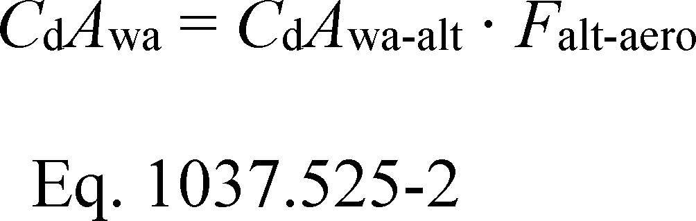
(2) Apply the following method for Phase 2 coastdown testing other than coastdown testing used to establish Falt-aero:
(i) Determine your drag area at the effective yaw angle from coastdown, CdAcoastdown(ψeff).
(ii) Use an alternate method to calculate the ratio of the wind-averaged drag area, CdAwa-alt (using an average of measurements at −4.5 and +4.5 degrees) to the drag area at the effective yaw angle, CdAalt(ψeff).
(iii) Determine your wind-averaged drag area, CdAwa, rounded to one decimal place, using the following equation:
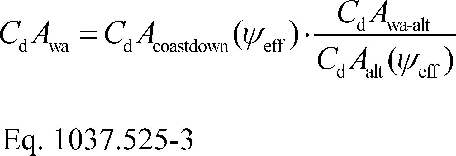
(3) Different approximations apply for Phase 1. For Phase 1 testing, you may correct your zero-yaw drag area as follows if the ratio of the zero-yaw drag area divided by yaw-sweep drag area for your vehicle is greater than 0.8065 (which represents the ratio expected for a typical Class 8 high-roof sleeper cab):
(i) Determine the zero-yaw drag area, CdAzero-yaw, and the yaw-sweep drag area for your vehicle using the same alternate method as specified in this subpart. Measure the drag area for 0°, −6°, and +6°. Use the arithmetic mean of the −6° and +6° drag areas as the ±6° drag area, CdA±6.
(ii) Calculate your yaw-sweep correction factor, CFys, using the following equation:

(iii) Calculate your corrected drag area for determining the aerodynamic bin by multiplying the measured zero-yaw drag area by CFys, as determined using Eq. 1037.525-4, as applicable. You may apply the correction factor to drag areas measured using other procedures. For example, apply CFys to drag areas measured using the coastdown method. If you use an alternate method, apply an alternate correction, Falt-aero, and calculate the final drag area using the following equation:
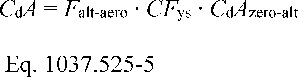
(iv) You may ask us to apply CFys to similar vehicles incorporating the same design features.
(v) As an alternative, you may calculate the wind-averaged drag area according to SAE J1252 (incorporated by reference in § 1037.810) and substitute this value into Eq. 1037.525-4 for the ±6° drag area.
(d) Approval of alternate methods. You must obtain preliminary approval before using any method other than coastdown testing to quantify aerodynamic drag. We will approve your request if you show that your procedures produce data that are the same as or better than coastdown testing with respect to repeatability and unbiased correlation. Note that the correlation is not considered to be biased if there is a bias before correction, but you remove the bias using Falt-aero. Send your request for approval to the Designated Compliance Officer. Keep records of the information specified in this paragraph (d). Unless we specify otherwise, include this information with your request. You must provide any information we require to evaluate whether you may apply the provisions of this section. Include additional information related to your alternate method as described in §§ 1037.530 through 1037.534. If you use a method other than those specified in this subpart, include all the following information, as applicable:
(1) Official name/title of the procedure.
(2) Description of the procedure.
(3) Cited sources for any standardized procedures that the method is based on.
(4) Description and rationale for any modifications/deviations from the standardized procedures.
(5) Data comparing the procedure to the coastdown reference procedure.
(6) Additional information specified for the alternate methods described in §§ 1037.530 through 1037.534 as applicable to this method (e.g., source location/address, background/history).
[86 FR 34473, June 29, 2021]
§ 1037.526 Aerodynamic measurements for trailers.
This section describes a methodology for determining aerodynamic drag area, CdA for use in determining input values for box vans as described in §§ 1037.515 and 1037.520.
(a) A trailer's aerodynamic performance for demonstrating compliance with standards is based on a ΔCdA value relative to a baseline trailer. Determine these ΔCdA values by performing A to B testing, as follows:
(1) Determine a baseline CdA value for a standard tractor pulling a test trailer representing a production configuration; use a 53-foot test trailer to represent long trailers and a 28-foot test trailer to represent short trailers. Repeat this testing with the same tractor and the applicable baseline trailer. For testing long trailers, the baseline trailer is a trailer meeting the specifications for a Phase 1 standard trailer in § 1037.501(g)(1); for testing refrigerated box vans, use a baseline trailer with an installed HVAC unit that properly represents a baseline configuration correlated with the production configuration. For testing short trailers, use a 28-foot baseline trailer with a single axle that meets the same specifications as the Phase 1 standard trailer, except as needed to accommodate the reduced trailer length.
(2) Use good engineering judgment to perform paired tests that accurately demonstrate the reduction in aerodynamic drag associated with the improved design. For example, the gap dimension should be the same for all paired tests, and effective yaw angle between paired tests should differ by no more than 1.0°.
(3) Measure CdA in m2 to two decimal places. Calculate ΔCdA by subtracting the drag area for the test trailer from the drag area for the baseline trailer.
(b) The default method for measuring is the wind-tunnel procedure as specified in § 1037.530. You may test using alternate methods as follows:
(1) If we approve it in advance, you may instead use one of the alternate methods specified in §§ 1037.528 through 1037.532, consistent with good engineering judgment, which may require that you adjust your test results from the alternate test method to correlate with the primary method. If you request our approval to determine ΔCdA using an alternate method, you must submit additional information as described in paragraph (d) of this section.
(2) The principles of 40 CFR 1065.10(c)(1) apply for aerodynamic test methods. Specifically, we may require that you use coastdown measurements if we determine that certain technologies are not suited to evaluation with wind-tunnel testing or CFD, such as nonrigid materials whose physical characteristics change in scaled-model testing. You may similarly reference 40 CFR 1065.10(c)(1) in your request to use coastdown testing as an alternate method.
(c) The following provisions apply for combining multiple devices under this section for the purpose of certifying trailers:
(1) If the device manufacturer establishes a ΔCdA value in a single test with multiple aerodynamic devices installed, trailer manufacturers may use that ΔCdA value directly for the same combination of aerodynamic devices installed on production trailers.
(2) Trailer manufacturers may combine ΔCdA values for aerodynamic devices that are not tested together, as long as each device does not significantly impair the effectiveness of another, consistent with good engineering judgment. To approximate the overall benefit of multiple devices, calculate a composite ΔCdA value for multiple aerodynamic devices by applying the full ΔCdA value for the device with the greatest aerodynamic improvement, adding the second-highest ΔCdA value multiplied by 0.9, and adding any other ΔCdA values multiplied by 0.8.
(d) You must send us a description of your plan to perform testing under this section before you start testing. We will evaluate whether plans for wind-tunnel testing meet the specifications of § 1037.530, and will tell you if you may or must use any other method to determine drag coefficients. We will approve your request to use an alternate method if you show that your procedures produce data that are the same as or better than wind-tunnel testing with respect to repeatability and unbiased correlation. Note that the correlation is not considered to be biased if there is a bias before correction, but you apply a correction to remove the bias. Send your testing plan to the Designated Compliance Officer. Keep records of the information specified in this paragraph (d). Unless we specify otherwise, include this information with your request. You must provide any information we require to evaluate whether you may apply the provisions of this section. Include additional information related to your alternate method as described in §§ 1037.528 through 1037.534.
§ 1037.527 Aerodynamic measurements for vocational vehicles.
This section describes a methodology for determining aerodynamic drag area, CdA, for use in determining input values for vocational vehicles as described in § 1037.520. This measurement is optional.
(a) Determine ΔCdA values by performing A to B testing as described for trailers in § 1037.526, with any appropriate adjustments, consistent with good engineering judgment.
(b) [Reserved]
§ 1037.528 Coastdown procedures for calculating drag area (CdA).
The coastdown procedures in this section describe how to calculate drag area, CdA, for Phase 2 tractors, trailers, and vocational vehicles, subject to the provisions of §§ 1037.525 through 1037.527. These procedures are considered the reference method for tractors, but an alternate method for trailers. Follow the provisions of Sections 1 through 9 of SAE J2263 (incorporated by reference in § 1037.810), with the clarifications and exceptions described in this section. Several of these exceptions are from SAE J1263 (incorporated by reference in § 1037.810). The coastdown procedures in 40 CFR 1066.310 apply instead of the provisions of this section for Phase 1 tractors.
(a) The terms and variables identified in this section have the meaning given in SAE J1263 and SAE J2263 unless specified otherwise.
(b) To determine CdA values for a tractor, perform coastdown testing with a tractor-trailer combination using the manufacturer's tractor and a standard trailer. To determine CdA values for a trailer, perform coastdown testing with a tractor-trailer combination using a standard tractor. Prepare tractors and trailers for testing as follows:
(1) Install instrumentation for performing the specified measurements.
(2) After adding vehicle instrumentation, verify that there is no brake drag or other condition that prevents the wheels from rotating freely. Do not apply the parking brake at any point between this inspection and the end of the measurement procedure.
(3) Install tires mounted on steel rims in a dual configuration (except for steer tires). The tires must -
(i) Be SmartWay-Verified or have a coefficient of rolling resistance at or below 5.1 kg/metric ton.
(ii) Have accumulated at least 2,000 miles but have no less than 50 percent of their original tread depth, as specified for truck cabs in SAE J1263.
(iii) Not be retreads or have any apparent signs of chunking or uneven wear.
(iv) Be size 295/75R22.5 or 275/80R22.5.
(v) Be inflated to the proper tire pressure as specified in Sections 6.6 and 8.1 of SAE J2263.
(vi) Be of the same tire model for a given axle.
(4) Perform an inspection or wheel alignment for both the tractor and the trailer to ensure that wheel position is within the manufacturer's specifications.
(c) The test condition specifications described in Sections 7.1 through 7.4 of SAE J1263 apply, with certain exceptions and additional provisions as described in this paragraph (c). These conditions apply to each run separately.
(1) We recommend that you not perform coastdown testing if winds are expected to exceed 6.0 mi/hr.
(2) The average of the component of the wind speed parallel to the road must not exceed 6.0 mi/hr. This constraint is in addition to those in Section 7.3 of SAE J1263.
(3) If road grade is greater than 0.02% over the length of the test surface, you must determine elevation as a function of distance along the length of the test surface and incorporate this into the analysis.
(4) Road grade may exceed 0.5% for limited portions of the test surface as long as it does not affect coastdown results, consistent with good engineering judgment.
(5) The road surface temperature must be at or below 50 °C. Use good engineering judgment to measure road surface temperature.
(d) CdA calculations are based on measured speed values while the vehicle coasts down through a high-speed range from 70 to 60 mi/hr, and through a low-speed range from 20 to 10 mi/hr. Disable any vehicle speed limiters that prevent travel above 72 mi/hr. Measure vehicle speed at a minimum recording frequency of 10 Hz, in conjunction with time-of-day data. Determine vehicle speed using either of the following methods:
(1) Complete coastdown runs. Operate the vehicle at a top speed above 72.0 mi/hr and allow the vehicle to coast down to 8.0 mi/hr or lower. Collect data for the high-speed range over a test segment that includes speeds from 72.0 down to 58.0 mi/hr, and collect data for the low-speed range over a test segment that includes speeds from 22.0 down to 8.0 mi/hr.
(2) Split coastdown runs. Collect data during a high-speed coastdown while the vehicle coasts through a test segment that includes speeds from 72.0 mi/hr down to 58.0 mi/hr. Similarly, collect data during a low-speed coastdown while the vehicle coasts through a test segment that includes speeds from 22.0 mi/hr down to 8.0 mi/hr. Perform one high-speed coastdown segment or two consecutive high-speed coastdown segments in one direction, followed by the same number of low-speed coastdown segments in the same direction, and then perform that same number of measurements in the opposite direction. You may not split runs as described in Section 9.3.1 of SAE J2263 except as allowed under this paragraph (d)(2).
(e) Measure wind speed, wind direction, air temperature, and air pressure at a recording frequency of 10 Hz, in conjunction with time-of-day data. Use at least one stationary anemometer and suitable data loggers meeting SAE J1263 specifications, subject to the following additional specifications for the anemometer placed along the test surface:
(1) You must start a coastdown measurement within 24 hours after completing zero-wind and zero-angle calibrations.
(2) Place the anemometer at least 50 feet from the nearest tree and at least 25 feet from the nearest bush (or equivalent features). Position the anemometer adjacent to the test surface, near the midpoint of the length of the track, between 2.5 and 3.0 body widths from the expected location of the test vehicle's centerline as it passes the anemometer. Record the location of the anemometer along the test track, to the nearest 10 feet.
(3) Mount the anemometer at a height that is within 6 inches of half the test vehicle's body height.
(4) The height of vegetation surrounding the anemometer may not exceed 10% of the anemometer's mounted height, within a radius equal to the anemometer's mounted height.
(f) Measure air speed and relative wind direction (yaw angle) onboard the vehicle at a minimum recording frequency of 10 Hz, in conjunction with time-of-day data, using an anemometer and suitable data loggers that meet the requirements of Sections 5.4 of SAE J2263. The yaw angle must be measured to a resolution and accuracy of ±0.5°. Mount the anemometer such that it measures air speed at 1.5 meters above the top of the leading edge of the trailer. If obstructions at the test site do not allow for this mounting height, then mount the anemometer such that it measures air speed at least 0.85 meters above the top of the leading edge of the trailer.
(g) Perform the following calculations to filter and correct measured data:
(1) For any measured values not identified as outliers, use those measured values directly in the calculations specified in this section. Filter air speed, yaw angle, wind speed, wind direction, and vehicle speed measurements to replace outliers for every measured value as follows:
(i) Determine a median measured value to represent the measurement point and the measurements 3 seconds before and after that point. In the first and last three seconds of the coastdown run, use all available data to determine the median measured value. The measurement window for determining the median value will accordingly include 61 measurements in most cases, and will always include at least 31 measurements (for 10 Hz recording frequency).
(ii) Determine the median absolute deviation corresponding to each measurement window from paragraph (g)(1)(i) of this section. This generally results from calculating 61 absolute deviations from the median measured value and determining the median from those 61 deviations. Calculate the standard deviation for each measurement window by multiplying the median absolute deviation by 1.4826; calculate three standard deviations by multiplying the median absolute deviation by 4.4478. Note that the factor 1.4826 is a statistical constant that relates median absolute deviations to standard deviations.
(iii) A measured value is an outlier if the measured value at a given point differs from the median measured value by more than three standard deviations. Replace each outlier with the median measured value from paragraph (g)(1)(i) of this section. This technique for filtering outliers is known as the Hampel method.
(2) For each high-speed and each low-speed segment, correct measured air speed using the wind speed and wind direction measurements described in paragraph (e) of this section as follows:
(i) Calculate the theoretical air speed, vair,th, for each 10-Hz set of measurements using the following equation:
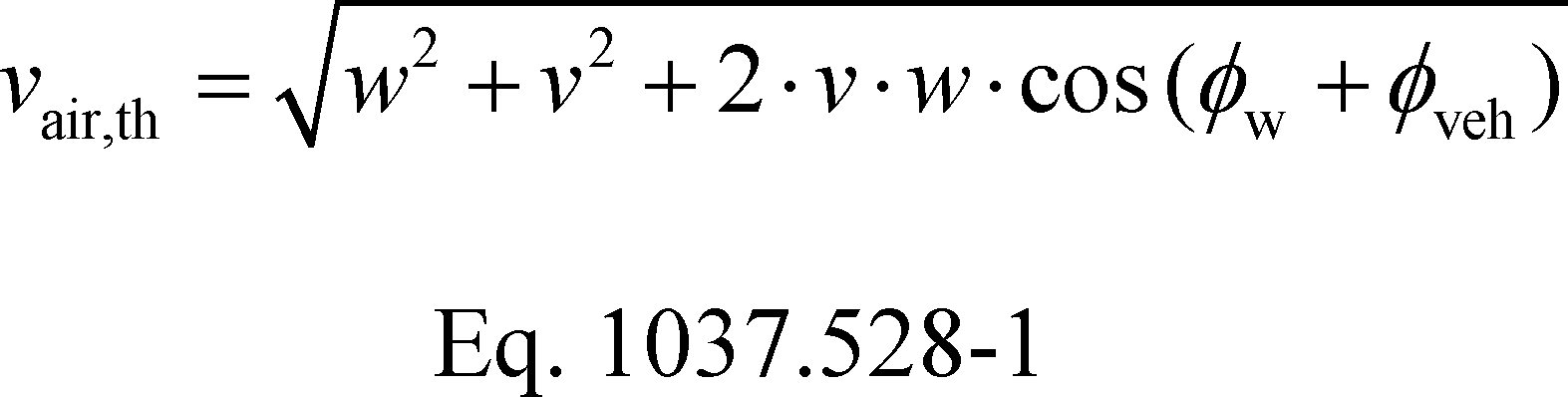
Where:
w = filtered wind speed.
v = filtered vehicle speed.
øw = filtered wind direction. Let øw = 0° for air flow in the first travel direction, with values increasing counterclockwise. For example, if the vehicle starts by traveling eastbound, then øw = 270° means a wind from the south.
øveh = the vehicle direction. Use øveh = 0° for travel in the first direction, and use øveh = 180° for travel in the opposite direction.
Example:
w = 7.1 mi/hr
v = 64.9 mi/hr
øw = 47.0°
øveh = 0°

vair,th = 69.93 mi/hr
(ii) Perform a linear regression using paired values of vair,th and measured air speed, vair,meas, to determine the air-speed correction coefficients, α0 and α1, based on the following equation:

(iii) Correct each measured value of air speed using the following equation:

(3) Correct measured air direction from all the high-speed segments using the wind speed and wind direction measurements described in paragraph (e) of this section as follows:
(i) Calculate the theoretical air direction, ψ;air,th, using the following equation:
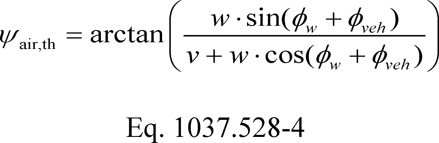
Example:
w = 7.1 mi/hr
v = 64.9 mi/hr
øw = 47.0°
øveh = 0°
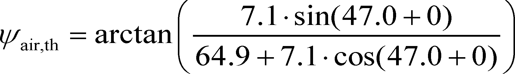
ψair,th = 4.26°
(ii) Perform a linear regression using paired values of ψair,th and measured air direction, ψair,meas, to determine the air-direction correction coefficients, β0 and β1, based on the following equation:

(iii) Correct each measured value of air direction using the following equation:

(h) Determine drag area, CdA, using the following procedure instead of the procedure specified in Section 10 of SAE J1263:
(1) Calculate the vehicle's effective mass, Me, to account for rotational inertia by adding 56.7 kg to the measured vehicle mass, M, (in kg) for each tire making road contact.
(2) Operate the vehicle and collect data over the high-speed range and low-speed range as specified in paragraph (d)(1) or (2) of this section. If the vehicle has a speed limiter that prevents it from exceeding 72 mi/hr, you must disable the speed limiter for testing.
(3) Calculate mean vehicle speed at each speed start point (70 and 20 mi/hr) and end point (60 and 10 mi/hr) as follows:
(i) Calculate the mean vehicle speed to represent the start point of each speed range as the arithmetic average of measured speeds throughout the continuous time interval that begins when measured vehicle speed is less than 2.00 mi/hr above the nominal starting speed point and ends when measured vehicle speed reaches 2.00 mi/hr below the nominal starting speed point, expressed to at least two decimal places. Calculate the timestamp corresponding to the starting point of each speed range as the average timestamp of the interval.
(ii) Repeat the calculations described in paragraph (h)(3)(i) of this section corresponding to the end point speed (60 or 10 mi/hr) to determine the time at which the vehicle reaches the end speed, and the mean vehicle speed representing the end point of each speed range.
(iii) If you incorporate grade into your calculations, use the average values for the elevation and distance traveled over each interval.
(4) Calculate the road-load force, F, for each speed range using the following equation:
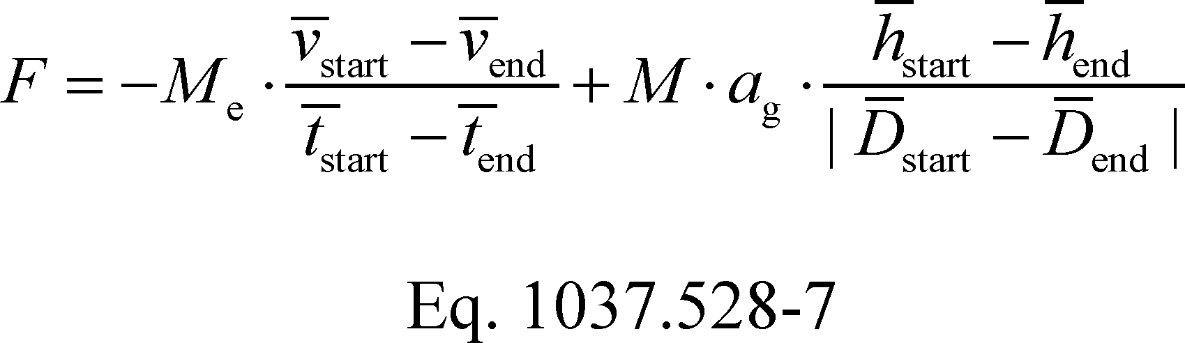
Where:
Me = the vehicle's effective mass.
v̄ = average vehicle speed at the start or end of each speed range, as described in paragraph (h)(3) of this section.
t̄ = timestamp at which the vehicle reaches the starting or ending speed expressed to at least one decimal place.
M = the vehicle's measured mass.
ag = acceleration of Earth's gravity, as described in 40 CFR 1065.630.
h̄ = average elevation at the start or end of each speed range expressed to at least two decimal places.
D̄ = distance traveled on the road surface from a fixed reference location along the road to the start or end of each speed range expressed to at least one decimal place.
Example:
Me = 17,129 kg (18 tires in contact with the road surface)
v̄start = 69.97 mi/hr = 31.28 m/s
v̄end = 59.88 mi/hr = 26.77 m/s
t̄start = 3.05 s
t̄end = 19.11 s
M = 16,108 kg
ag = 9.8061 m/s2
h̄start = 0.044 m
h̄end = 0.547 m
D̄start = 706.8 ft = 215.4 m
D̄end = 2230.2 ft = 697.8 m

F = 4645.5 N
(5) For tractor testing, calculate the drive-axle spin loss force at high and low speeds, Fspin[speed], and determine ΔFspin as follows:
(i) Use the results from the axle efficiency test described in § 1037.560 for the drive axle model installed in the tractor being tested for this coastdown procedure.
(ii) Perform a second-order regression of axle power loss in W from only the zero-torque test points with wheel speed, fnwheel, in r/s from the axle efficiency test to determine coefficients c0, c1, and c2.
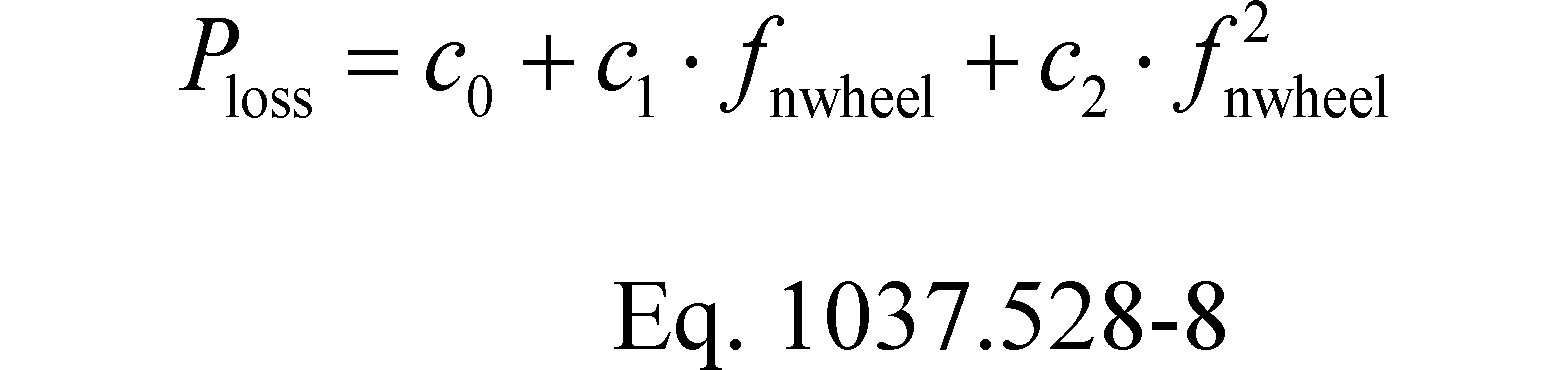
(iii) Calculate Fspin[speed] using the following equation:
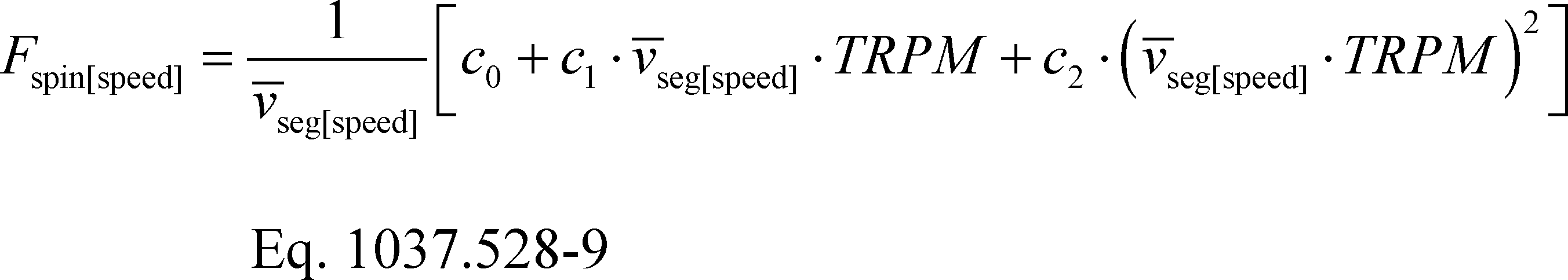
Where:
v̄seg[speed] = the mean vehicle speed of all vehicle speed measurements in each low-speed and high-speed segment.
TRPM = tire revolutions per mile for the drive tire model installed on the tractor being tested according to § 1037.520(c)(1).
Example:
v̄seghi = 28.86 m/s
v̄seglo = 5.84 m/s
TRPM = 508 r/mi = 0.315657 r/m
c0 = −206.841 W
c1 = 239.8279 W·s/r
c2 = 21.27505 W·s2/r2

Fspinhi = 129.7 N
Fspinlo = 52.7 N
(iv) Calculate ΔFspin using the following equation:

Example:
ΔFspin = 129.7−52.7 = 77.0 N
(6) For tractor testing, calculate the tire rolling resistance force at high and low speeds for steer, drive, and trailer axle positions, FTRR[speed,axle], and determine ΔFTRR, the rolling resistance difference between 65 mi/hr and 15 mi/hr, for each tire as follows:
(i) Conduct a stepwise coastdown tire rolling resistance test with three tires for each tire model installed on the vehicle using SAE J2452 (incorporated by reference in § 1037.810) for the following test points (which replace the test points in Table 3 of SAE J2452):
Table 1 of § 1037.528 - Stepwise Coastdown Test Points for Determining Tire Rolling Resistance as a Function of Speed
| Step Number | Load (% of max) |
Inflation pressure (% of max) |
|---|---|---|
| 1 | 20 | 100 |
| 2 | 55 | 70 |
| 3 | 85 | 120 |
| 4 | 85 | 100 |
| 5 | 100 | 95 |
(ii) Calculate FTRR[speed,axle] using the following equation:
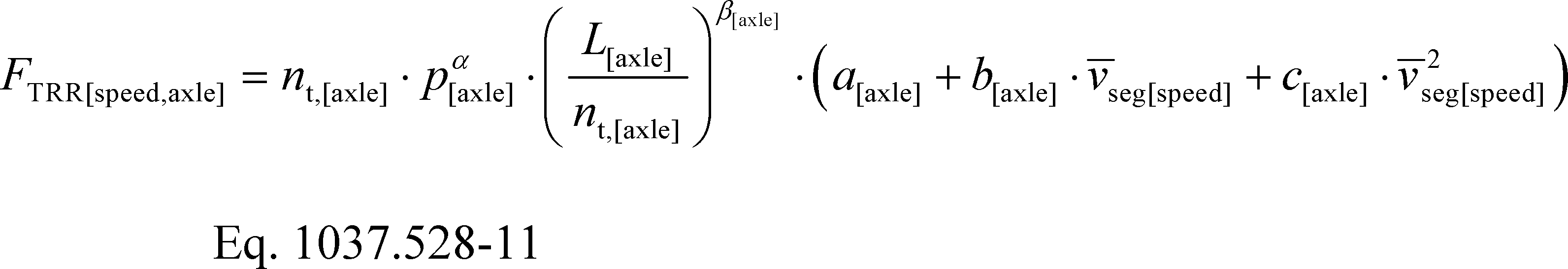
Where:
nt,[axle] = number of tires at the axle position.
p[axle] = the inflation pressure set and measured on the tires at the axle position at the beginning of the coastdown test.
L[axle] = the load over the axle at the axle position on the coastdown test vehicle.
α[axle], β[axle], a[axle], b[axle], and c[axle] = regression coefficients from SAE J2452 that are specific to axle position.
Example:
nt,steer = 2
psteer = 758.4 kPa
Lsteer = 51421.2 N
αsteer = −0.2435
βsteer = 0.9576
asteer = 0.0434
bsteer = 5.4·10−5
csteer = 5.53·10−7
nt,drive = 8
pdrive = 689.5 kPa
Ldrive = 55958.4 N
αdrive = −0.3146
βdrive = 0.9914
adrive = 0.0504
bdrive = 1.11·10−4
cdrive = 2.86·10−7
nt,trailer = 8
ptrailer = 689.5 kPa
Ltrailer = 45727.5 N
αtrailer = −0.3982
βtrailer = 0.9756
atrailer = 0.0656
btrailer = 1.51·10−4
ctrailer = 2.94·10−7
vseghi = 28.86 m/s = 103.896 km/hr
vseglo = 5.84 m/s = 21.024 km/hr

FTRRhi,steer = 365.6 N
FTRRhi,drive = 431.4 N
FTRRhi,trailer = 231.7 N
FTRRlo,steer = 297.8 N
FTRRlo,drive = 350.7 N
FTRRlo,trailer = 189.0 N
(iii) Calculate FTRR[speed] by summing the tire rolling resistance calculations at a given speed for each axle position:
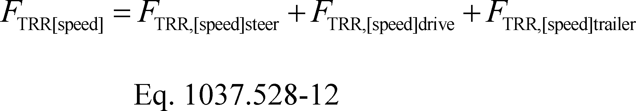
Example:
FTRRhi = 365.6 + 431.4 + 231.7 = 1028.7 N
FTRRlo = 297.8 + 350.7 + 189.0 = 837.5 N
(iv) Adjust FTRR[speed] to the ambient temperature during the coastdown segment as follows:

Where:
Tseg[speed] = the average ambient temperature during the coastdown segment, in °C.
Example:
FTRRhi = 1028.7 N
FTRRlo = 837.5 N
Tseghi = 25.5 °C
Tseglo = 25.1 °C
FTRRhi,adj = 1 + 0.006·(24−25.5)] = 1019.4 N
FTRRlo,adj = 837.5·[1 + 0.006·(24−25.1] = 832.0 N
(v) Determine the difference in rolling resistance between 65 mph and 15 mph, ΔFTRR, for each tire. Use good engineering judgment to consider the multiple results. For example, you may ignore the test results for the tires with the highest and lowest differences and use the result from the remaining tire. Determine ΔFTRR as follows:

Example:
ΔFTRR = 1019.4−832.0 = 187.4 N
(7) For trailer testing, determine ΔFTRR using a default value adjusted to the ambient temperature instead of performing a rolling resistance test, as follows:

Where:
ΔFTRR,def = default rolling resistance force speed adjustment; Use 215 N for long box vans and 150 N for short box vans.
T̄coast = the average ambient temperature during both low and high speed segments.
Example:
ΔFTRR,def = 215 N
T̄coast = 25.5 °C
ΔFTRR = 215·[1 + 0.0006·(24−25.5)] = 213.1 N
(8) Square the air speed measurements and calculate average squared air speed during each speed range for each run,v̄2air,hi and v̄2air,lo.
(9) Average the Flo and v̄2air,lo values for each pair of runs in opposite directions. If running complete coastdowns as described in paragraph (d)(1) or one high-speed segment per direction as described in paragraph (d)(2), average every two Flo and v̄2air,lo values. If running two high-speed segments per direction as described in paragraph (d)(2), average every four Flo and v̄2air,lo values. Use these values as Flo,pair and v̄2air,lo,pair in the calculations in this paragraph (h) to apply to each of the two or four high-speed segments from the same runs as the low-speed segments used to determine Flo,pair and v̄2air,lo,pair.
(10) Calculate average air temperature T̄ and air pressure P̄act during each high-speed run.
(11) Calculate drag area, CdA, in m2 for each high-speed segment using the following equation, expressed to at least three decimal places:

Where:
Fhi = road load force at high speed determined from Eq. 1037.528-7.
Flo,pair = the average of Flo values for a pair of opposite direction runs calculated as described in paragraph (h)(9) of this section.
ΔFspin = the difference in drive-axle spin loss force between high-speed and low-speed coastdown segments. This is described in paragraph (h)(5) of this section for tractor testing. Let ΔFspin = 110 N for trailer testing.
ΔFTRR = the difference in tire rolling resistance force between high-speed and low-speed coastdown segments as described in paragraphs (h)(6) or (7) of this section.
v̄2air,lo,pair = the average of v̄2air,lo values for a pair of opposite direction runs calculated as described in paragraph (h)(9) of this section.
R = specific gas constant = 287.058 J/(kg·K).
T̄ = mean air temperature expressed to at least one decimal place.
P̄act = mean absolute air pressure expressed to at least one decimal place.
Example:
Fhi = 4645.5 N
Flo,pair = 1005.0 N
ΔFspin = 77.0 N
ΔFTRR = 187.4 N
v̄2air,hi = 933.4 m2/s2
v̄2air,lo,pair = 43.12 m2/s2
R = 287.058 J/(kg·K)
T̄ = 285.97 K
P̄act = 101.727 kPa = 101727 Pa

CdA = 6.120 m2
(12) Calculate your final CdA value from the high-speed segments as follows:
(i) Eliminate all points where there were known equipment problems or other measurement problems.
(ii) Of the remaining points, calculate the median of the absolute value of the yaw angles, ψmed, and eliminate all CdA values that differ by more than 1.0° from ψmed.
(iii) Of the remaining points, calculate the mean and standard deviation of CdA and eliminate all values that differ by more than 2.0 standard deviations from the mean value.
(iv) There must be at least 24 points remaining. Of the remaining points, recalculate the mean yaw angle. Round the mean yaw angle to the nearest 0.1°. This final result is the effective yaw angle, ψeff, for coastdown testing.
(v) For the same set of points, recalculate the mean CdA. This is the final result of the coastdown test, CdAcoastdown(ψeff).
(i) [Reserved]
(j) Include the following information in your application for certification:
(1) The name, location, and description of your test facilities, including background/history, equipment and capability, and track and facility elevation, along with the grade and size/length of the track.
(2) Test conditions for each test result, including date and time, wind speed and direction, ambient temperature and humidity, vehicle speed, driving distance, manufacturer name, test vehicle/model type, model year, applicable family, tire type and rolling resistance, weight of tractor-trailer (as tested), and driver identifier(s).
(3) Average CdA and yaw angle results and all the individual run results (including voided or invalid runs).
[81 FR 74048, Oct. 25, 2016, as amended at 86 FR 34474, June 29, 2021]
§ 1037.530 Wind-tunnel procedures for calculating drag area (CdA).
The wind-tunnel procedure specified in this section is considered to be the primary procedure for trailers, but is an alternate procedure for tractors.
(a) You may measure drag areas consistent with published SAE procedures as described in this section using any wind tunnel recognized by the Subsonic Aerodynamic Testing Association, subject to the provisions of §§ 1037.525 through 1037.527. If your wind tunnel does not meet the specifications described in this section, you may ask us to approve it as an alternate method under § 1037.525(d) or § 1037.526(d). All wind tunnels and wind tunnel tests must meet the specifications described in SAE J1252 (incorporated by reference in § 1037.810), with the following exceptions and additional provisions:
(1) The Overall Vehicle Reynolds number, Re#w, must be at least 1.0·106. Tests for Reynolds effects described in Section 7.1 of SAE J1252 are not required.
(2) For full-scale wind tunnel tractor testing, use good engineering judgment to select a trailer that is a reasonable representation of the trailer used for reference coastdown testing. For example, where your wind tunnel is not long enough to test the tractor with a standard 53 foot box van, it may be appropriate to use a shorter box van. In such a case, the correlation developed using the shorter trailer would only be valid for testing with the shorter trailer.
(3) For reduced-scale wind tunnel testing, use a one-eighth or larger scale model of a tractor and trailer that is sufficient to simulate airflow through the radiator inlet grill and across an engine geometry that represents engines commonly used in your test vehicle.
(b) Open-throat wind tunnels must also meet the specifications of SAE J2071 (incorporated by reference in § 1037.810).
(c) To determine CdA values for certifying tractors, perform wind-tunnel testing with a tractor-trailer combination using the manufacturer's tractor and a standard trailer. To determine CdA values for certifying trailers, perform wind-tunnel testing with a tractor-trailer combination using a standard tractor. Use a moving/rolling floor if the facility has one. For Phase 1 tractors, conduct the wind tunnel tests at a zero yaw angle. For Phase 2 vehicles, conduct the wind tunnel tests by measuring the drag area at yaw angles of +4.5° and −4.5° and calculating the average of those two values.
(d) In your request to use wind-tunnel testing for tractors, or in your application for certification for trailers, describe how you meet all the specifications that apply under this section, using terminology consistent with SAE J1594 (incorporated by reference in § 1037.810). If you request our approval to use wind-tunnel testing even though you do not meet all the specifications of this section, describe how your method nevertheless qualifies as an alternate method under § 1037.525(d) or 1037.526(d) and include all the following information:
(1) Identify the name and location of the test facility for your wind-tunnel method.
(2) Background and history of the wind tunnel.
(3) The wind tunnel's layout (with diagram), type, and construction (structural and material).
(4) The wind tunnel's design details: The type and material for corner turning vanes, air settling specification, mesh screen specification, air straightening method, tunnel volume, surface area, average duct area, and circuit length.
(5) Specifications related to the wind tunnel's flow quality: Temperature control and uniformity, airflow quality, minimum airflow velocity, flow uniformity, angularity and stability, static pressure variation, turbulence intensity, airflow acceleration and deceleration times, test duration flow quality, and overall airflow quality achievement.
(6) Test/working section information: Test section type (e.g., open, closed, adaptive wall) and shape (e.g., circular, square, oval), length, contraction ratio, maximum air velocity, maximum dynamic pressure, nozzle width and height, plenum dimensions and net volume, maximum allowed model scale, maximum model height above road, strut movement rate (if applicable), model support, primary boundary layer slot, boundary layer elimination method, and photos and diagrams of the test section.
(7) Fan section description: fan type, diameter, power, maximum angular speed, maximum speed, support type, mechanical drive, and sectional total weight.
(8) Data acquisition and control (where applicable): Acquisition type, motor control, tunnel control, model balance, model pressure measurement, wheel drag balances, wing/body panel balances, and model exhaust simulation.
(9) Moving ground plane or rolling road (if applicable): Construction and material, yaw table and range, moving ground length and width, belt type, maximum belt speed, belt suction mechanism, platen instrumentation, temperature control, and steering.
(10) Facility correction factors and purpose.
[81 FR 74048, Oct. 25, 2016, as amended at 86 FR 34476, June 29, 2021]
§ 1037.532 Using computational fluid dynamics to calculate drag area (CdA).
This section describes how to use commercially available computational fluid dynamics (CFD) software to determine CdA values, subject to the provisions of §§ 1037.525 through 1037.527. This is considered to be an alternate method for both tractors and trailers.
(a) For Phase 2 vehicles, use SAE J2966 (incorporated by reference in § 1037.810), with the following clarifications and exceptions:
(1) Vehicles are subject to the requirement to meet standards based on the average of testing at yaw angles of +4.5° and −4.5°; however, you may submit your application for certification with CFD results based on only one of those yaw angles.
(2) For CFD code with a Navier-Stokes based solver, follow the additional steps in paragraph (d) of this section. For Lattice-Boltzmann based CFD code, follow the additional steps in paragraph (e) of this section.
(3) Simulate a Reynolds number of 5.1 million (based on a 102-inch trailer width) and an air speed of 65 mi/hr.
(4) Perform an open-road simulation (not the Wind Tunnel Simulation).
(5) Use a free stream turbulence intensity of 0.0%.
(6) Choose time steps that can accurately resolve intrinsic flow instabilities, consistent with good engineering judgment.
(7) The result must be drag area (CdA), not drag coefficient (Cd), based on an air speed of 65 mi/hr.
(8) Submit information as described in paragraph (g) of this section.
(b) For Phase 1 tractors, apply the procedures as specified in paragraphs (c) through (f) of this section. Paragraphs (c) through (f) of section apply for Phase 2 vehicles only as specified in paragraph (a) of this section.
(c) To determine CdA values for certifying a tractor, perform CFD modeling based on a tractor-trailer combination using the manufacturer's tractor and a standard trailer. To determine CdA values for certifying a trailer, perform CFD modeling based on a tractor-trailer combination using a standard tractor. Perform all CFD modeling as follows:
(1) Specify a blockage ratio at or below 0.2% to simulate open-road conditions.
(2) Assume zero yaw angle.
(3) Model the tractor with an open grill and representative back pressures based on available data describing the tractor's pressure characteristics.
(4) Enable the turbulence model and mesh deformation.
(5) Model tires and ground plane in motion to simulate a vehicle moving forward in the direction of travel.
(6) Apply the smallest cell size to local regions on the tractor and trailer in areas of high flow gradients and smaller-geometry features (e.g., the A-pillar, mirror, visor, grille and accessories, trailer-leading edge, trailer-trailing edge, rear bogey, tires, and tractor-trailer gap).
(7) Simulate a vehicle speed of 55 mi/hr.
(d) Take the following steps for CFD code with a Navier-Stokes formula solver:
(1) Perform an unstructured, time-accurate analysis using a mesh grid size with a total volume element count of at least 50 million cells of hexahedral and/or polyhedral mesh cell shape, surface elements representing the geometry consisting of no less than 6 million elements, and a near-wall cell size corresponding to a y+ value of less than 300.
(2) Perform the analysis with a turbulence model and mesh deformation enabled (if applicable) with boundary layer resolution of ±95%. Once the results reach this resolution, demonstrate the convergence by supplying multiple, successive convergence values for the analysis. The turbulence model may use k-epsilon (k-ε), shear stress transport k-omega (SST k-ω), or other commercially accepted methods.
(e) For Lattice-Boltzmann based CFD code, perform an unstructured, time-accurate analysis using a mesh grid size with total surface elements of at least 50 million cells using cubic volume elements and triangular and/or quadrilateral surface elements with a near-wall cell size of no greater than 6 mm on local regions of the tractor and trailer in areas of high flow gradients and smaller geometry features, with cell sizes in other areas of the mesh grid starting at twelve millimeters and increasing in size from this value as the distance from the tractor and trailer increases.
(f) You may ask us to allow you to perform CFD analysis using parameters and criteria other than those specified in this section, consistent with good engineering judgment. In your request, you must demonstrate that you are unable to perform modeling based on the specified conditions (for example, you may have insufficient computing power, or the computations may require inordinate time), or you must demonstrate that different criteria (such as a different mesh cell shape and size) will yield better results. In your request, you must also describe your recommended alternative parameters and criteria, and describe how this approach will produce results that adequately represent a vehicle's in-use performance. We may require that you supply data demonstrating that your selected parameters and criteria will provide a sufficient level of detail to yield an accurate analysis. If you request an alternative approach because it will yield better results, we may require that you perform CFD analysis using both your recommended criteria and parameters and the criteria and parameters specified in this section to compare the resulting key aerodynamic characteristics, such as pressure profiles, drag build-up, and turbulent/laminar flow at key points around the tractor-trailer combination.
(g) Include the following information in your request to determine CdA values using CFD:
(1) The name of the software.
(2) The date and version number of the software.
(3) The name of the company producing the software and the corresponding address, phone number, and Web site.
(4) Identify whether the software uses Navier-Stokes or Lattice-Boltzmann equations.
(5) Describe the input values you will use to simulate the vehicle's aerodynamic performance for comparing to coastdown results.
[81 FR 74048, Oct. 25, 2016, as amended at 86 FR 34476, June 29, 2021]
§ 1037.534 Constant-speed procedure for calculating drag area (CdA).
This section describes how to use constant-speed aerodynamic drag testing to determine CdA values, subject to the provisions of § 1037.525. This is considered to be an alternate method for tractors.
(a) Test track. Select a test track that meets the specifications described in § 1037.528(c)(3).
(b) Ambient conditions. At least two tests are required. For one of the tests, ambient conditions must remain within the specifications described in § 1037.528(c) throughout the preconditioning and measurement procedure. The other tests must also meet those specifications except for the wind conditions. The wind conditions must be such that 80 percent of the values of yaw angle, ψ̄air, from the 50 mi/hr and 70 mi/hr test segments are between 4° and 10° or between −4° and −10°.
(c) Vehicle preparation. Perform testing with a tractor-trailer combination using the manufacturer's tractor and a standard trailer. Prepare tractors and trailers for testing as described in § 1037.528(b). Install measurement instruments meeting the requirements of 40 CFR part 1065, subpart C, that have been calibrated as described in 40 CFR part 1065, subpart D, as follows:
(1) Measure torque at each of the drive wheels using a hub torque meter or a rim torque meter. If testing a tractor with two drive axles, you may disconnect one of the drive axles from receiving torque from the driveshaft, in which case you would measure torque at only the wheels that receive torque from the driveshaft. Set up instruments to read engine speed for calculating angular speed at the point of the torque measurements, or install instruments for measuring the angular speed of the wheels directly.
(2) Install instrumentation to measure vehicle speed at 10 Hz, with an accuracy and resolution of 0.1 mi/hr. Also install instrumentation for reading engine speed from the engine's onboard computer.
(3) Mount an anemometer on the trailer as described in § 1037.528(f).
(4) Fill the vehicle's fuel tanks so they are at maximum capacity at the start of the measurement procedure.
(5) Measure the weight over each axle to the nearest 20 kg, with a full fuel tank, including the driver and any passengers that will be in the vehicle during the test.
(d) Measurement procedure. The measurement sequence consists of vehicle preconditioning followed by stabilization and measurement over five consecutive constant-speed test segments with three different speed setpoints (10, 50, and 70 mi/hr). Each test segment is divided into smaller increments for data analysis.
(1) Precondition the vehicle and zero the torque meters as follows:
(i) If you are using rim torque meters, zero the torque meters by lifting each instrumented axle and recording torque signals for at least 30 seconds, and then drive the vehicle at 50 mi/hr for at least 30 minutes.
(ii) If you are using any other kind of torque meter, drive the vehicle at 50 mi/hr for at least 30 minutes, and then allow the vehicle to coast down from full speed to a complete standstill while the clutch is disengaged or the transmission is in neutral, without braking. Zero the torque meters within 60 seconds after the vehicle stops moving by recording the torque signals for at least 30 seconds, and directly resume vehicle preconditioning at 50 mi/hr for at least 1.25 mi.
(iii) You may calibrate instruments during the preconditioning drive.
(2) Perform testing as described in paragraph (d)(3) of this section over a sequence of test segments at constant vehicle speed as follows:
(i) 300±30 seconds in each direction at 10 mi/hr.
(ii) 450±30 seconds in each direction at 70 mi/hr.
(iii) 450±30 seconds in each direction at 50 mi/hr.
(iv) 450±30 seconds in each direction at 70 mi/hr.
(v) 450±30 seconds in each direction at 50 mi/hr.
(vi) 300±30 seconds in each direction at 10 mi/hr.
(3) When the vehicle preconditioning described in paragraph (d)(1) of this section is complete, stabilize the vehicle at the specified speed for at least 200 meters and start taking measurements. The test segment starts when you start taking measurements for all parameters.
(4) During the test segment, continue to operate the vehicle at the speed setpoint, maintaining constant speed and torque within the ranges specified in paragraph (e) of this section. Drive the vehicle straight with minimal steering; do not change gears. Perform measurements as follows during the test segment:
(i) Measure the angular speed of the driveshaft, axle, or wheel where the torque is measured, or calculate it from engine speed in conjunction with gear and axle ratios, as applicable.
(ii) Measure vehicle speed in conjunction with time-of-day data.
(iii) Measure ambient conditions, air speed, and air direction as described in § 1037.528(e) and (f). Correct air speed and air direction as described in paragraphs (f)(1) and (2) of this section.
(5) You may divide a test segment into multiple passes by suspending and resuming measurements. Stabilize vehicle speed before resuming measurements for each pass as described in paragraph (d)(3) of this section. Analyze the data from multiple passes by combining them into a single sequence of measurements for each test segment.
(6) Divide measured values into even 10 second increments. If the last increment for each test segment is less than 10 seconds, disregard measured values from that increment for all calculations under this section.
(e) Validation criteria. Analyze measurements to confirm that the test is valid. Analyze vehicle speed and drive torque by calculating the mean speed and torque values for each successive 1 second increment, for each successive 10 second increment, and for each test segment. The test is valid if the data conform to all the following specifications:
(1) Vehicle speed. The mean vehicle speed for the test segment must be within 1.00 mi/hr of the speed setpoint. In addition, for testing at 50 mi/hr and 70 mi/hr, all ten of the 1 second mean vehicle speeds used to calculate a corresponding 10 second mean vehicle speed must be within ±0.2 mi/hr of that 10 second mean vehicle speed. Perform the same data analysis for testing at 10 mi/hr, but apply a validation threshold of ±0.1 mi/hr.
(2) Drive torque. All ten of the 1 second mean torque values used to calculate a corresponding 10 second mean torque value must be within ±50% of that 10 second mean torque value.
(3) Torque drift. Torque meter drift may not exceed ±1%. Determine torque meter drift by repeating the procedure described in paragraph (d)(1) of this section after testing is complete, except that driving the vehicle is necessary only to get the vehicle up to 50 mi/hr as part of coasting to standstill.
(f) Calculations. Analyze measured data for each time segment after time-aligning all the data. Use the following calculations to determine CdA:
(1) Onboard air speed. Correct onboard anemometer measurements for air speed using onboard measurements and measured ambient conditions as described in § 1037.528(f), except that you must first divide the test segment into consecutive 10 second increments. Disregard data from the final increment of the test segment if it is less than 10 seconds. This analysis results in the following equation for correcting air speed measurements:

(2) Yaw angle. Correct the onboard anemometer measurements for air direction for each test segment as follows:
(i) Calculate arithmetic mean values for vehicle speed, v̄, wind speed, w̄, and wind direction, ϕ̄w, over each 10 second increment for each test segment. Disregard data from the final increment of the test segment if it is less than 10 seconds.
(ii) Calculate the theoretical air direction, ψ̄air,th, for each 10 second increment using the following equation:
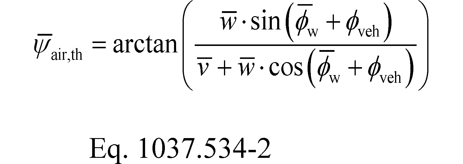
Where:
ϕveh = the vehicle direction, as described in § 1037.528(f)(2).
Example:
w̄ = 7.1 mi/hr
v̄ = 69.9 mi/hr
ϕ̄w = 47.0°
ϕ̄veh = 0°

ψ̄air,th = 3.97°
(iii) Perform a linear regression using paired values of ψ̄air,th and measured air direction, ψ̄air,meas, from each 10 second increment for all 50 mi/hr and 70 mi/hr test segments to determine the air-direction correction coefficients, β0 and β1, based on the following equation:
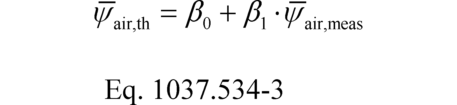
(iv) For all 50 mi/hr and 70 mi/hr test segments, correct each measured value of air direction using the following equation:

(3) Road load force.
(i) Average the sum of the corrected torques, the average of the wheel speed measurements, and the vehicle speed over every 10 second increment to determine, T̄total, f̄nwheel, and v̄.
(ii) Calculate a mean road load force, F̄RL[speed], for each 10 second increment using the following equation:
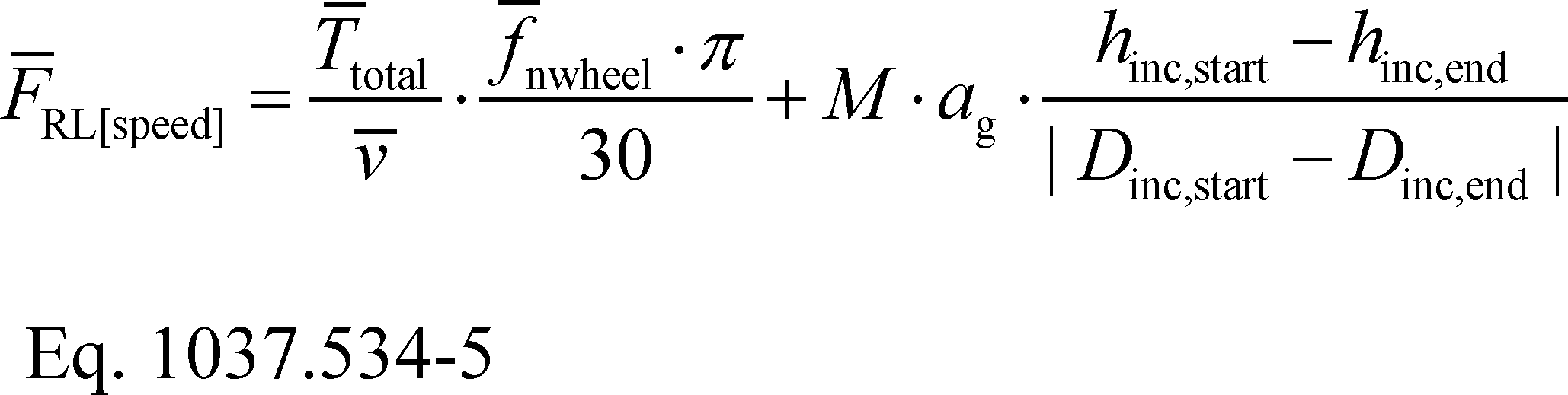
Where:
T̄total = mean of all corrected torques at a point in time.
v̄ = mean vehicle speed.
f̄nwheel = mean wheel speed.
M = the measured vehicle mass.
ag = acceleration of Earth's gravity, as described in 40 CFR 1065.630.
hinc = elevation at the start or end of each 10 second increment expressed to at least two decimal places.
Dinc = distance traveled on the road surface from a fixed reference location along the road to the start or end of each 10 second increment, expressed to at least one decimal place.
Example:
T̄total = 2264.9 N·m
v̄ = 31.6 m/s
f̄nwheel =598.0 r/min
M = 16508 kg
ag = 9.8061 m/s2
hinc,start = 0.044 m
hinc,end = 0.574 m
Dinc,start = 215.4 m
Dinc,end = 697.8 m
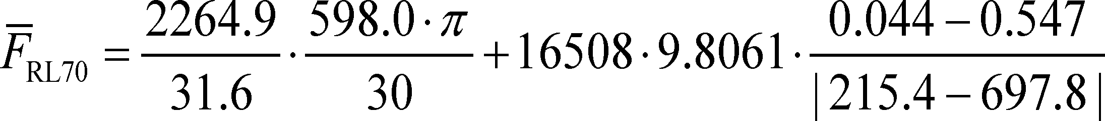
F̄RL70 = 4310.6 N
(4) Determination of drag area. Calculate a vehicle's drag area as follows:
(i) Calculate the mean road load force from all 10 second increments from the 10 mi/hr test segments from the test that was within the wind limits specified in § 1037.528(c), F̄RL10,test. This value represents the mechanical drag force acting on the vehicle.
(ii) Calculate the mean aerodynamic force for each 10 second increment, F̄aero[speed], from the 50 mi/hr and 70 mi/hr test segments by subtracting F̄RL10,test from F̄RL[speed].
(iii) Average the corrected air speed and corrected yaw angle over every 10 second segment from the 50 mi/hr and 70 mi/hr test segments to determine v̄air and ψ̄air.
(iv) Calculate CdA for each 10 second increment from the 50 mi/hr and 70 mi/hr test segments using the following equation:

Where:
CdAi[speed] = the mean drag area for each 10 second increment, i.
Faero[speed] = mean aerodynamic force over a given 10 second increment = F̄RL[speed] −F̄RL10,test.
Vair[speed] = mean aerodynamic force over a given 10 second increment.
R = specific gas constant = 287.058 J/(kg·K).
T = mean air temperature.
pact = mean absolute air pressure.
Example:
FRL70 = 4310.6 N
FRL10,test = 900.1 N
Faero70 = 4310.6−900.1 = 3410.5 N
V2air70 = 1089.5 m2/s2
R = 287.058 J/(kg·K)
T = 293.68 K
pact = 101300 Pa
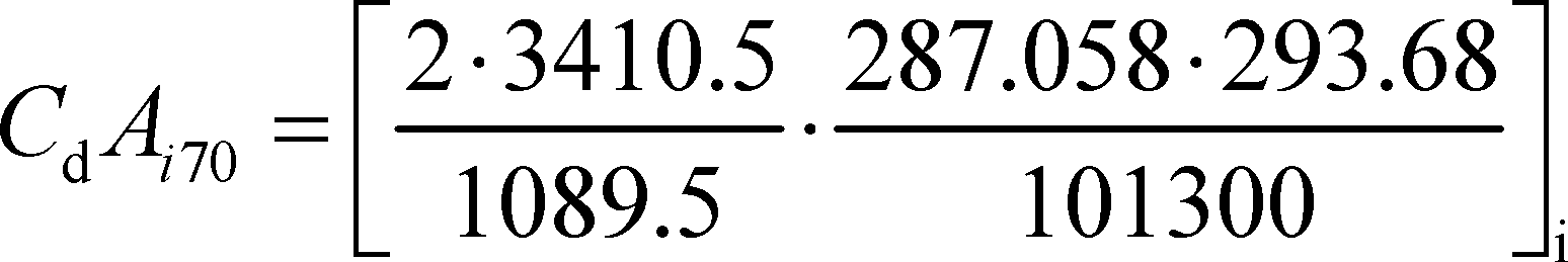
CdAi70 = 5.210 m2
(v) Plot all CdA values from the 50 mi/hr and 70 mi/hr test segments against the corresponding values for corrected yaw angle for each 10 second increment. Create a regression based on a fourth-order polynomial regression equation of the following form:
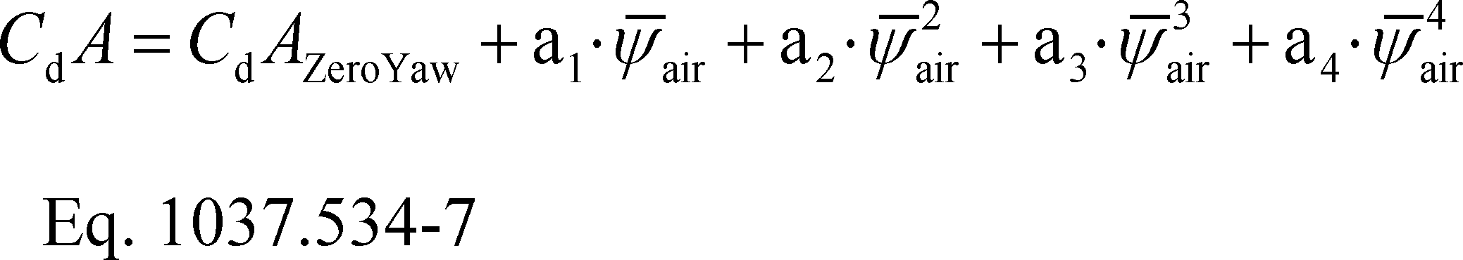
(vi) Determine CdAwa-alt as the average of CdA values at 4.5° and −4.5° by applying Eq. 1037.534-7 at those angles.
(g) Documentation. Keep the following records related to the constant-speed procedure for calculating drag area:
(1) The measurement data for calculating CdA as described in this section.
(2) A general description and pictures of the vehicle tested.
(3) The vehicle's maximum height and width.
(4) The measured vehicle mass.
(5) Mileage at the start of the first test segment and at the end of the last test segment.
(6) The date of the test, the starting time for the first test segment, and the ending time for the last test segment.
(7) The transmission gear used for each test segment.
(8) The data describing how the test was valid relative to the specifications and criteria described in paragraphs (b) and (e) of this section.
(9) A description of any unusual events, such as a vehicle passing the test vehicle, or any technical or human errors that may have affected the CdA determination without invalidating the test.
[81 FR 74048, Oct. 25, 2016, as amended at 86 FR 34476, June 29, 2021]
§ 1037.540 Special procedures for testing vehicles with hybrid power take-off.
This section describes optional procedures for quantifying the reduction in greenhouse gas emissions for vehicles as a result of running power take-off (PTO) devices with a hybrid energy delivery system. See § 1037.550 for powertrain testing requirements that apply for drivetrain hybrid systems. The procedures are written to test the PTO by ensuring that the engine produces all of the energy with no net change in stored energy (charge-sustaining), and for plug-in hybrid vehicles, also allowing for drawing down the stored energy (charge-depleting). The full charge-sustaining test for the hybrid vehicle is from a fully charged renewable energy storage system (RESS) to a depleted RESS and then back to a fully charged RESS. You must include all hardware for the PTO system. You may ask us to modify the provisions of this section to allow testing hybrid vehicles other than electric-battery hybrids, consistent with good engineering judgment. For plug-in hybrids, use a utility factor to properly weight charge-sustaining and charge-depleting operation as described in paragraph (f)(3) of this section.
(a) Select two vehicles for testing as follows:
(1) Select a vehicle with a hybrid energy delivery system to represent the range of PTO configurations that will be covered by the test data. If your test data will represent more than one PTO configuration, use good engineering judgment to select the configuration with the maximum number of PTO circuits that has the smallest potential reduction in greenhouse gas emissions.
(2) Select an equivalent conventional vehicle as specified in § 1037.615.
(b) Measure PTO emissions from the fully warmed-up conventional vehicle as follows:
(1) Without adding a restriction, instrument the vehicle with pressure transducers at the outlet of the hydraulic pump for each circuit. Perform pressure measurements with a frequency of at least 1 Hz.
(2) Operate the PTO system with no load for at least 15 seconds. Measure gauge pressure and record the average value over the last 10 seconds (p̄min). For hybrid PTO systems the measured pressure with no load is typically zero. Apply maximum operator demand to the PTO system until the pressure relief valve opens and pressure stabilizes; measure gauge pressure and record the average value over the last 10 seconds (p̄max).
(3) Denormalize the PTO duty cycle in appendix II of this part using the following equation:
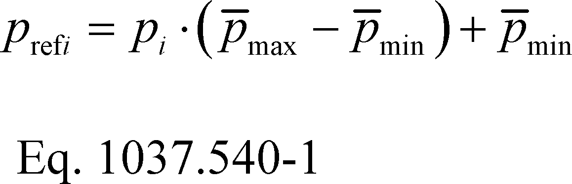
Where:
prefi = the reference pressure at each point i in the PTO cycle.
pi = the normalized pressure at each point i in the PTO cycle (relative to pmax).
pmax = the mean maximum pressure measured in paragraph (b)(2) of this section.
pmin = the mean minimum pressure measured in paragraph (b)(2) of this section.
(4) If the PTO system has two circuits, repeat paragraph (b)(2) and (3) of this section for the second PTO circuit.
(5) Install a system to control pressures in the PTO system during the cycle.
(6) Start the engine.
(7) Depending on the number of circuits the PTO system has, operate the vehicle over one or concurrently over both of the denormalized PTO duty cycles in Appendix II of this part. Measure emissions during operation over each duty cycle using the provisions of 40 CFR part 1066.
(8) Measured pressures must meet the cycle-validation specifications in the following table for each test run over the duty cycle:
Table 1 of § 1037.540 - Statistical Criteria for Validating Each Test Run Over the Duty Cycle
| Parametera | Pressure |
|---|---|
| Slope, a1 | 0.950 ≤ a1 ≤ 1.030. |
| Absolute value of intercept, |a0| | ≤2.0% of maximum mapped pressure. |
| Standard error of the estimate, SEE | ≤10% of maximum mapped pressure. |
| Coefficient of determination, r2 | ≥0.970. |
(c) Measure PTO emissions from the fully warmed-up hybrid vehicle as follows:
(1) Perform the steps in paragraphs (b)(1) through (5) of this section.
(2) Prepare the vehicle for testing by operating it as needed to stabilize the RESS at a full state of charge (or equivalent for non-electric RESS).
(i) For plug-in hybrid electric vehicles, we recommend charging the battery with an external electrical source.
(ii) For other vehicles, we recommend running back-to-back PTO tests until engine operation is initiated to charge the RESS. The RESS should be fully charged once engine operation stops. The ignition should remain in the “on” position.
(3) Turn the vehicle and PTO system off while the sampling system is being prepared.
(4) Turn the vehicle and PTO system on such that the PTO system is functional, whether it draws power from the engine or a battery.
(5) Operate the vehicle over one or both of the denormalized PTO duty cycles without turning the vehicle off, until the engine starts and then shuts down. This may require running multiple repeats of the PTO duty cycles. For non-PHEV systems the test cycle is completed once the engine shuts down. For plug-in hybrid systems, continue running until the PTO hybrid is running in a charge-sustaining mode such that the “End of Test” requirements defined in 40 CFR 1066.501 are met. Measure emissions as described in paragraph (b)(7) of this section. Use good engineering judgment to minimize the variability in testing between the two types of vehicles.
(6) For plug-in hybrid electric vehicles, follow 40 CFR 1066.501 to divide the test into charge-depleting and charge-sustaining operation.
(7) Apply cycle-validation criteria as described in paragraph (b)(8) of this section to both charge-sustaining and charge-depleting operation.
(d) Calculate the equivalent distance driven based on operating time for each section of the PTO portion of the test as applicable by determining the time of the test and applying the conversion factor in paragraph (d)(4) of this section. For testing where fractions of a cycle were run (for example, where three cycles are completed and the halfway point of a fourth PTO cycle is reached before the engine starts and shuts down again), calculate the time of the test, ttest, as follows:
(1) Add up the time run for all complete tests.
(2) For fractions of a test, use the following equation to calculate the time:
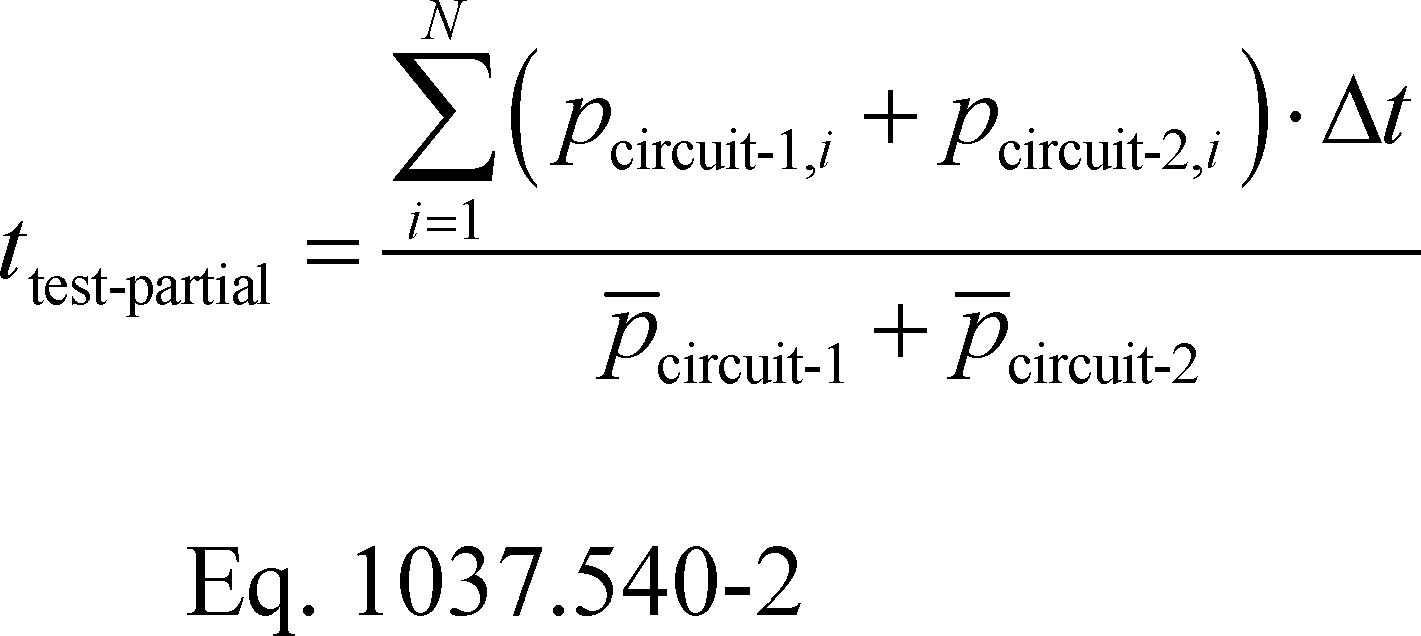
Where:
i = an indexing variable that represents one recorded value.
N = number of measurement intervals.
pcircuit-1,i = normalized pressure command from circuit 1 of the PTO cycle for each point, i, starting from i = 1.
pcircuit-2,i = normalized pressure command from circuit 2 of the PTO cycle for each point, i, starting from i = 1. Let pcircuit-2 = 0 if there is only one circuit.
pcircuit-1 = the mean normalized pressure command from circuit 1 over the entire PTO cycle.
pcircuit-2 = the mean normalized pressure command from circuit 2 over the entire PTO cycle. Let pcircuit-2 = 0 if there is only one circuit.
Δt = the time interval between measurements. For example, at 100 Hz, Δt = 0.0100 seconds.
(3) Sum the time from the complete cycles and from the partial cycle.
(4) Divide the total PTO operating time from paragraph (d)(3) of this section by a conversion factor of 0.0144 hr/mi for Phase 1 and 0.0217 hr/mi for Phase 2 to determine the equivalent distance driven. The conversion factors are based on estimates of average vehicle speed and PTO operating time as a percentage of total engine operating time; the Phase 2 conversion factor is calculated from an average speed of 27.1 mi/hr and PTO operation 37% of engine operating time, as follows:

(e) For Phase 1, calculate combined cycle-weighted emissions of the four duty cycles for vocational vehicles, for both the conventional and hybrid PTO vehicle tests, as follows:
(1) Calculate the CO2 emission rates in grams per test without rounding for both the conventional vehicle and the charge-sustaining and charge-depleting portions of the test for the hybrid vehicle as applicable.
(2) Divide the CO2 mass from the PTO cycle by the distance determined in paragraph (d)(4) of this section and the standard payload as defined in § 1037.801 to get the CO2 emission rate in g/ton-mile. For plug-in hybrid electric vehicles follow paragraph (f)(3) of this section to calculate utility factor weighted CO2 emissions in g/ton-mile.
(3) Calculate the g/ton-mile emission rate for the driving portion of the test specified in § 1037.510 and add this to the CO2 g/ton-mile emission rate for the PTO portion of the test.
(4) Follow the provisions of § 1037.615 to calculate improvement factors and benefits for advanced technologies.
(f) For Phase 2, calculate the delta PTO fuel results for input into GEM during vehicle certification as follows:
(1) Calculate fuel consumption in grams per test, mfuelPTO, without rounding, as described in 40 CFR 1036.540(d)(4) for both the conventional vehicle and the charge-sustaining and charge-depleting portions of the test for the hybrid vehicle as applicable.
(2) Divide the fuel mass by the applicable distance determined in paragraph (d)(4) of this section and the appropriate standard payload as defined in § 1037.801 to determine the fuel rate in g/ton-mile.
(3) For plug-in hybrid electric vehicles calculate the utility factor weighted fuel consumption in g/ton-mile, as follows:
(i) Determine the utility factor fraction for the PTO system from the table in appendix V of this part using interpolation based on the total time of the charge-depleting portion of the test as determined in paragraphs (c)(6) and (d)(3) of this section.
(ii) Weight the emissions from the charge-sustaining and charge-depleting portions of the test using the following equation:

Where:
mPTO,CD = mass of fuel per ton-mile while in charge-depleting mode.
UFt,CD = utility factor fraction at time tCD as determined in paragraph (f)(3)(i) of this section.
mPTO,CS = mass of fuel per ton-mile while in charge-sustaining mode.
(4) Calculate the difference between the conventional PTO emissions result and the hybrid PTO emissions result for input into GEM.
(g) If the PTO system has more than two circuits, apply the provisions of this section using good engineering judgment.
[81 FR 74048, Oct. 25, 2016, as amended at 86 FR 34477, June 29, 2021]
§ 1037.550 Powertrain testing.
This section describes the procedure to measure fuel consumption and create engine fuel maps by testing a powertrain that includes an engine coupled with a transmission, drive axle, and hybrid components or any assembly with one or more of those hardware elements. Engine fuel maps are part of demonstrating compliance with Phase 2 vehicle standards under this part; the powertrain test procedure in this section is one option for generating this fuel-mapping information as described in 40 CFR 1036.503. Additionally, this powertrain test procedure is one option for certifying hybrids to the engine standards in 40 CFR 1036.108.
(a) General provisions. The following provisions apply broadly for testing under this section:
(1) Measure NOX emissions as described in paragraph (k) of this section. Include these measured NOX values any time you report to us your greenhouse gas emissions or fuel consumption values from testing under this section.
(2) The procedures of 40 CFR part 1065 apply for testing in this section except as specified. This section uses engine parameters and variables that are consistent with 40 CFR part 1065.
(3) Powertrain testing depends on models to calculate certain parameters. You can use the detailed equations in this section to create your own models, or use the GEM HIL model (incorporated by reference in § 1037.810) to simulate vehicle hardware elements as follows:
(i) Create driveline and vehicle models that calculate the angular speed setpoint for the test cell dynamometer, ƒnref,dyno, based on the torque measurement location. Use the detailed equations in paragraph (f) of this section, the GEM HIL model's driveline and vehicle submodels, or a combination of the equations and the submodels. You may use the GEM HIL model's transmission submodel in paragraph (f) of this section to simulate a transmission only if testing hybrid engines.
(ii) Create a driver model or use the GEM HIL model's driver submodel to simulate a human driver modulating the throttle and brake pedals to follow the test cycle as closely as possible.
(iii) Create a cycle-interpolation model or use the GEM HIL model's cycle submodel to interpolate the duty-cycles and feed the driver model the duty-cycle reference vehicle speed for each point in the duty-cycle.
(4) The powertrain test procedure in this section is designed to simulate operation of different vehicle configurations over specific duty cycles. See paragraphs (h) and (j) of this section.
(5) For each test run, record engine speed and torque as defined in 40 CFR 1065.915(d)(5) with a minimum sampling frequency of 1 Hz. These engine speed and torque values represent a duty cycle that can be used for separate testing with an engine mounted on an engine dynamometer under § 1037.551, such as for a selective enforcement audit as described in § 1037.301.
(6) For hybrid powertrains with no plug-in capability, correct for the net energy change of the energy storage device as described in 40 CFR 1066.501. For PHEV powertrains, follow 40 CFR 1066.501 to determine End-of-Test for charge-depleting operation. You must get our approval in advance for your utility factor curve; we will approve it if you can show that you created it from sufficient in-use data of vehicles in the same application as the vehicles in which the PHEV powertrain will be installed.
(b) Test configuration. Select a powertrain for testing as described in § 1037.235 or 40 CFR 1036.235 as applicable. Set up the engine according to 40 CFR 1065.110 and 1065.405(b). Set the engine's idle speed to the minimum warm-idle speed. If warm idle speed is not adjustable, simply let the engine operate at its warm idle speed.
(1) The default test configuration consists of a powertrain with all components upstream of the axle. This involves connecting the powertrain's output shaft directly to the dynamometer or to a gear box with a fixed gear ratio and measuring torque at the axle input shaft. You may instead set up the dynamometer to connect at the wheel hubs and measure torque at that location. The preceding sentence may apply if your powertrain configuration requires it, such as for hybrid powertrains or if you want to represent the axle performance with powertrain test results.
(2) For testing hybrid engines, connect the engine's crankshaft directly to the dynamometer and measure torque at that location.
(c) Powertrain temperatures during testing. Cool the powertrain during testing so temperatures for oil, coolant, block, head, transmission, battery, and power electronics are within the manufacturer's expected ranges for normal operation. You may use electronic control module outputs to comply with this paragraph (c). You may use auxiliary coolers and fans.
(d) Engine break in. Break in the engine according to 40 CFR 1065.405, the axle assembly according to § 1037.560, and the transmission according to § 1037.565. You may instead break in the powertrain as a complete system using the engine break in procedure in 40 CFR 1065.405.
(e) Dynamometer setup. Set the dynamometer to operate in speed-control mode (or torque-control mode for hybrid engine testing at idle, including idle portions of transient duty cycles). Record data as described in 40 CFR 1065.202. Command and control the dynamometer speed at a minimum of 5 Hz, or 10 Hz for testing engine hybrids. Run the vehicle model to calculate the dynamometer setpoints at a rate of at least 100 Hz. If the dynamometer's command frequency is less than the vehicle model dynamometer setpoint frequency, subsample the calculated setpoints for commanding the dynamometer setpoints.
(f) Driveline and vehicle model. Use the GEM HIL model's driveline and vehicle submodels or the equations in this paragraph (f) to calculate the dynamometer speed setpoint, ƒnref,dyno, based on the torque measurement location. Note that the GEM HIL model is configured to set the accessory load to zero and it comes configured with the tire slip model disabled.
(1) Driveline model with a transmission in hardware. For testing with torque measurement at the axle input shaft or wheel hubs, calculate, ƒnref,dyno, using the GEM HIL model's driveline submodel or the following equation:

Where:
ka[speed] = drive axle ratio as determined in paragraph (h) of this section. Set ka[speed] equal to 1.0 if torque is measured at the wheel hubs.
vrefi = simulated vehicle reference speed as calculated in paragraph (f)(3) of this section.
r[speed] = tire radius as determined in paragraph (h) of this section.
(2) Driveline model with a simulated transmission. For testing with the torque measurement at the engine's crankshaft, ƒnref,dyno is the dynamometer target speed from the GEM HIL model's transmission submodel. You may request our approval to change the transmission submodel, as long as the changes do not affect the gear selection logic. Before testing, initialize the transmission model with the engine's measured torque curve and the applicable steady-state fuel map from the GEM HIL model. You may request our approval to input your own steady-state fuel map. Configure the torque converter to simulate neutral idle when using this procedure to generate engine fuel maps in 40 CFR 1036.503 or to perform the Supplemental Emission Test (SET) testing under 40 CFR 1036.505. You may change engine commanded torque at idle to better represent CITT for transient testing under 40 CFR 1036.510. You may change the simulated engine inertia to match the inertia of the engine under test. We will evaluate your requests under paragraph (f)(3) of this section based on your demonstration that that the adjusted testing better represents in-use operation.
(i) The transmission submodel needs the following model inputs:
(A) Torque measured at the engine's crankshaft.
(B) Engine estimated torque determined from the electronic control module or by converting the instantaneous operator demand to an instantaneous torque in N·m.
(C) Dynamometer mode when idling (speed-control or torque-control).
(D) Measured engine speed when idling.
(E) Transmission output angular speed, ƒni,transmission, calculated as follows:
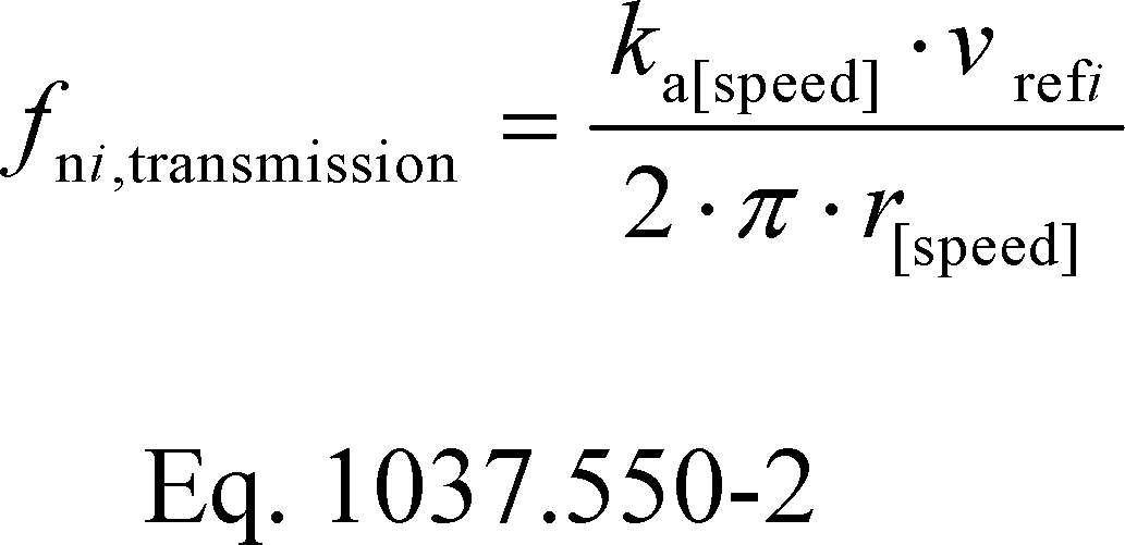
Where:
ka[speed] = drive axle ratio as determined in paragraph (h) of this section.
vrefi = simulated vehicle reference speed as calculated in paragraph (f)(3) of this section.
r[speed] = tire radius as determined in paragraph (h) of this section.
(ii) The transmission submodel generates the following model outputs:
(A) Dynamometer target speed.
(B) Dynamometer idle load.
(C) Transmission engine load limit.
(D) Engine speed target.
(3) Vehicle model. Calculate the simulated vehicle reference speed, νrefi, using the GEM HIL model's vehicle submodel or the equations in this paragraph (f)(3):
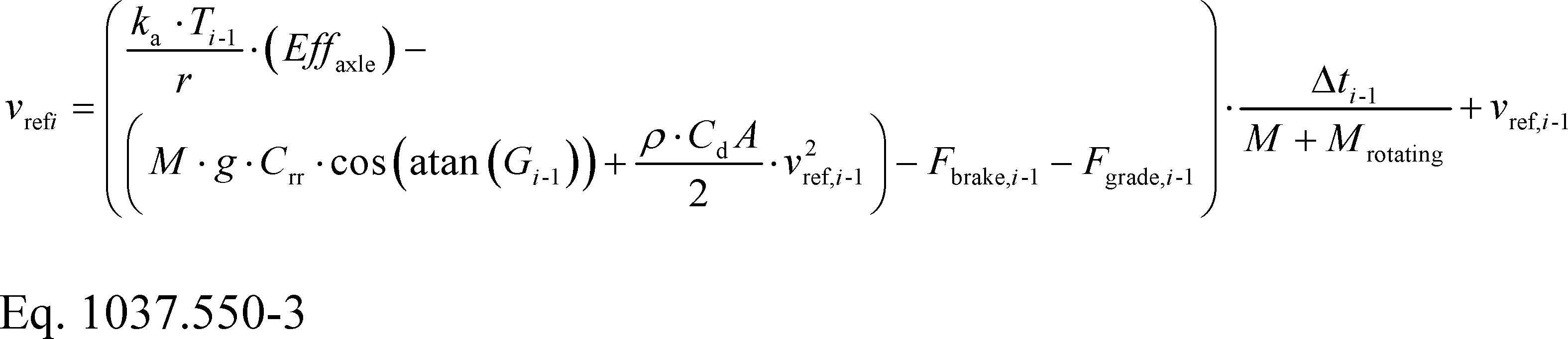
Where:
i = a time-based counter corresponding to each measurement during the sampling period. Let vref1 = 0; start calculations at i = 2. A 10-minute sampling period will generally involve 60,000 measurements.
T = instantaneous measured torque at the axle input, measured at the wheel hubs, or simulated by the GEM HIL model's transmission submodel.
Eƒƒaxle = axle efficiency. Use Eƒƒaxle = 0.955 for T ≥ 0, and use Eƒƒaxle = 1/0.955 for T < 0. Use Eƒƒaxle = 1.0 if torque is measured at the wheel hubs.
M = vehicle mass for a vehicle class as determined in paragraph (h) of this section.
g = gravitational constant = 9.80665 m/s2.
Crr = coefficient of rolling resistance for a vehicle class as determined in paragraph (h) of this section.
Gi-1 = the percent grade interpolated at distance, Di-1, from the duty cycle in appendix IV to this part corresponding to measurement (i-1).
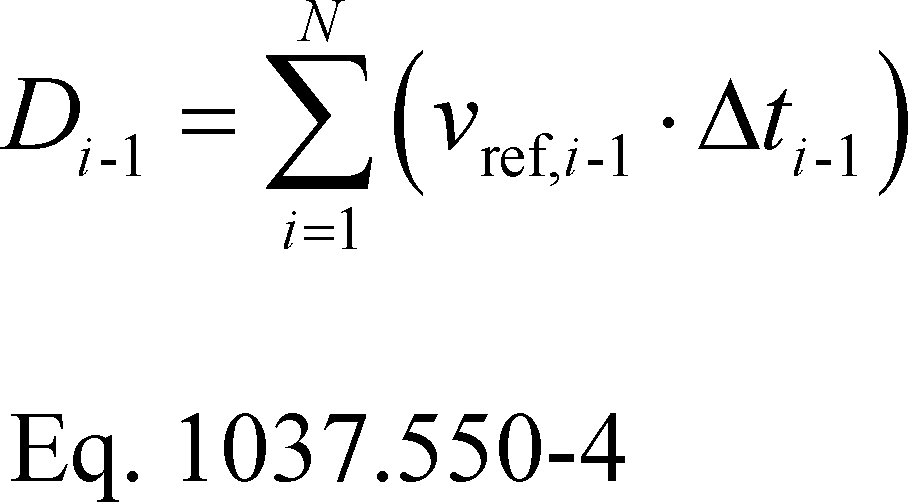
ρ = air density at reference conditions. Use ρ = 1.1845 kg/m3.
CdA = drag area for a vehicle class as determined in paragraph (h) of this section.
Fbrake,i-1 = instantaneous braking force applied by the driver model.

Δt = the time interval between measurements. For example, at 100 Hz, Δt = 0.0100 seconds.
Mrotating = inertial mass of rotating components. Let Mrotating = 340 kg for vocational Light HDV or vocational Medium HDV. See paragraph (h) of this section for tractors and for vocational Heavy HDV.
(4) Example. The following example illustrates a calculation of ƒnref,dyno using paragraph (f)(1) of this section where torque is measured at the axle input shaft. This example is for a vocational Light HDV or vocational Medium HDV with 6 speed automatic transmission at B speed (Test 4 in Table 2 of 40 CFR 1036.540).
kαB = 4.0
rB = 0.399 m
T999 = 500.0 N·m
Crr = 7.7 kg/tonne = 7.7·10-3 kg/kg
M = 11408 kg
Cd = 5.4 m2
G999 = 0.39% = 0.0039
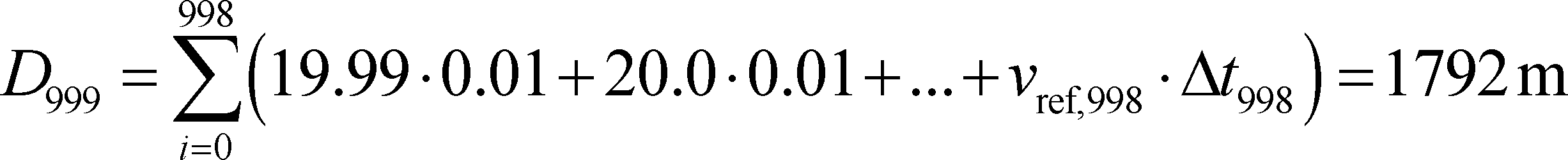
Fbrake,999 = 0 N
vref,999 = 20.0 m/s
Fgrade,999 = 11408·9.81·sin (atan(0.0039)) = 436.5 N
Δt = 0.0100 s
Mrotating = 340 kg

(g) Driver model. Use the GEM HIL model's driver submodel or design a driver model to simulate a human driver modulating the throttle and brake pedals. In either case, tune the model to follow the test cycle as closely as possible meeting the following specifications:
(1) The driver model must meet the speed requirements for operation over the highway cruise cycles as described in § 1037.510 and for operation over the transient cycle as described in 40 CFR 1066.425(b). The exceptions in 40 CFR 1066.425(b)(4) apply to the transient cycle and the highway cruise cycles.
(2) Send a brake signal when operator demand is zero and vehicle speed is greater than the reference vehicle speed from the test cycle. Include a delay before changing the brake signal to prevent dithering, consistent with good engineering judgment.
(3) Allow braking only if operator demand is zero.
(4) Compensate for the distance driven over the duty cycle over the course of the test. Use the following equation to perform the compensation in real time to determine your time in the cycle:

Where:
vvehicle = measured vehicle speed.
vcycle = reference speed from the test cycle. If vcycle,i-1 < 1.0 m/s, set vcycle,i-1 = vvehicle,i-1.
(h) Vehicle configurations to evaluate for generating fuel maps as defined in 40 CFR 1036.503. Configure the driveline and vehicle models from paragraph (f) of this section in the test cell to test the powertrain. Simulate multiple vehicle configurations that represent the range of intended vehicle applications. Use at least three equally spaced axle ratios or tire sizes and three different road loads (nine configurations), or at least four equally spaced axle ratios or tire sizes and two different road loads (eight configurations). Select axle ratios to represent the full range of expected vehicle installations.
(1) Determine the vehicle model inputs for M, Mrotating, Cd, and Crr for a set of vehicle configurations as described in 40 CFR 1036.540(c)(3). Instead of selecting axle ratios and tire sizes based on the range of intended vehicle applications as described in this paragraph (h), you may select axle ratios and tire sizes such that the ratio of engine speed to vehicle speed covers the range of ratios of minimum and maximum engine speed to vehicle speed when the transmission is in top gear for the vehicles in which the powertrain will be installed. Note that you do not have to use the same axle ratios and tire sizes for each GEM regulatory subcategory.
(2) For hybrid powertrain systems where the transmission will be simulated, use the transmission parameters defined in Table 1 of 40 CFR 1036.540 to determine transmission type and gear ratio. Use a fixed transmission efficiency of 0.95. The GEM HIL transmission model uses a transmission parameter file for each test that includes the transmission type, gear ratios, lockup gear, torque limit per gear from Table 1 of 40 CFR 1036.540, and the values from 40 CFR 1036.503(b)(4) and (c).
(i) [Reserved]
(j) Duty cycles to evaluate. Operate the powertrain over each of the duty cycles specified in § 1037.510(a)(2), and for each applicable vehicle configuration from paragraph (h) of this section. Determine cycle-average powertrain fuel maps by testing the powertrain using the procedures in 40 CFR 1036.540(d) with the following exceptions:
(1) Understand “engine” to mean “powertrain”.
(2) If the preceding duty cycle does not end at 0 mi/hr, transition between duty cycles by decelerating at a rate of 2 mi/hr/s at 0% grade until the vehicle reaches zero speed. Shut off the powertrain. Prepare the powertrain and test cell for the next duty-cycle. Start the next duty-cycle within 60 to 180 seconds after shutting off the powertrain. Do not run the powertrain or change its physical state before starting the next duty cycle. If the next duty cycle begins at 0 mi/hr vehicle speed, key on the vehicle and start the duty-cycle after 10 seconds, otherwise key on the vehicle and transition to the next duty cycle by accelerating at a rate of 1 mi/hr/s at 0% grade for vehicle configurations given in Table 2 of 40 CFR 1036.540 or 2 mi/hr/s at 0% grade for vehicle configurations given in Tables 3 and 4 of 40 CFR 1036.540, then stabilize for 10 seconds at the initial duty cycle conditions.
(3) Calculate cycle work using GEM or the speed and torque from the driveline and vehicle models from paragraph (f) of this section to determine the sequence of duty cycles.
(4) Calculate the mass of fuel consumed for idle duty cycles as described in paragraph (n) of this section.
(5) Warm up the powertrain as described in 40 CFR 1036.527(c)(1).
(k) Measuring NOX emissions. Measure NOX emissions for each sampling period in grams. You may perform these measurements using a NOX emission-measurement system that meets the requirements of 40 CFR part 1065, subpart J. If a system malfunction prevents you from measuring NOX emissions during a test under this section but the test otherwise gives valid results, you may consider this a valid test and omit the NOX emission measurements; however, we may require you to repeat the test if we determine that you inappropriately voided the test with respect to NOX emission measurement.
(l) [Reserved]
(m) Measured output speed validation. For each test point, validate the measured output speed with the corresponding reference values. If the range of reference speed is less than 10 percent of the mean reference speed, you need to meet only the standard error of the estimate in Table 1 of this section. You may delete points when the vehicle is stopped. If your speed measurement is not at the location of fnref, correct your measured speed using the constant speed ratio between the two locations. Apply cycle-validation criteria for each separate transient or highway cruise cycle based on the following parameters:
Table 1 of § 1037.550 - Statistical Criteria for Validating Duty Cycles
| Parameter a | Speed control |
|---|---|
| Slope, a;1 | 0.990 ≤a1 ≤1.010. |
| Absolute value of intercept, |a0| | ≤2.0% of maximum ƒnref speed. |
| Standard error of the estimate, SEE | ≤2.0% of maximum ƒnref speed. |
| Coefficient of determination, r2 | ≥0.990. |
(n) Fuel consumption at idle. Determine the mass of fuel consumed at idle for the applicable duty cycles described in § 1037.510(a)(2) as follows:
(1) Measure fuel consumption with a fuel flow meter and report the mean idle fuel mass flow rate for each duty cycle as applicable, ṁ̅fuelidle.
(2) If you do not measure fuel mass flow rate, calculate the idle fuel mass flow rate for each duty cycle, ṁ̅fuelidle, for each set of vehicle settings, as follows:

Where:
MC = molar mass of carbon.
wCmeas = carbon mass fraction of fuel (or mixture of test fuels) as determined in 40 CFR 1065.655(d), except that you may not use the default properties in Table 1 of 40 CFR 1065.655 to determine α, β, and wC for liquid fuels.
ṅ̅exh = the mean raw exhaust molar flow rate from which you measured emissions according to 40 CFR 1065.655.
xCcombdry = the mean concentration of carbon from fuel and any injected fluids in the exhaust per mole of dry exhaust.
xH2Oexhdry = the mean concentration of H2O in exhaust per mole of dry exhaust.
ṁ̅CO2DEF = the mean CO2 mass emission rate resulting from diesel exhaust fluid decomposition over the duty cycle as determined in 40 CFR 1036.535(b)(7). If your engine does not use diesel exhaust fluid, or if you choose not to perform this correction, set ṁ̅CO2DEF equal to 0.
MCO2 = molar mass of carbon dioxide.
Example:
MC = 12.0107 g/mol
wCmeas = 0.867
ṅ̅exh = 25.534 mol/s
xCcombdry = 2.805·10−3 mol/mol
xH2Oexhdry = 3.53·10−2 mol/mol
ṁ̅CO2DEF = 0.0726 g/s
MCO2 = 44.0095
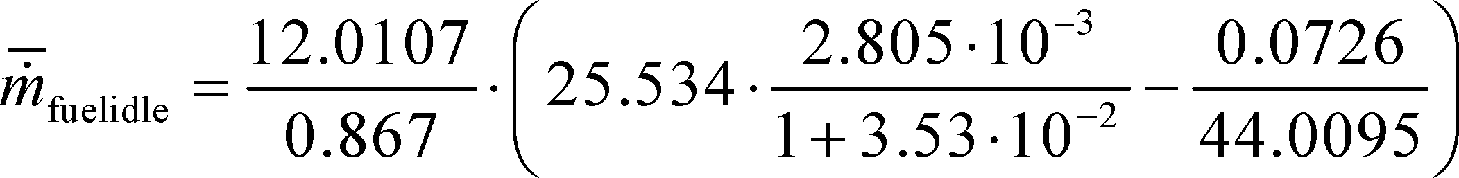
ṁ̅fuelidle = 0.405 g/s = 1458.6 g/hr
(o) Create GEM inputs. Use the results of powertrain testing to determine GEM inputs for the different simulated vehicle configurations as follows:
(1) Correct the measured or calculated fuel masses, mfuel[cycle], and mean idle fuel mass flow rates, ṁ̅fuelidle, if applicable, for each test result to a mass-specific net energy content of a reference fuel as described in 40 CFR 1036.535(f), replacing ṁ̅fuel with mfuel[cycle] where applicable in Eq. 1036.535-4.
(2) Declare fuel masses, mfuel[cycle], in g/cycle. In addition, declare mean fuel mass flow rate for each applicable idle duty cycle, ṁ̅fuelidle. These declared values may not be lower than any corresponding measured values determined in this section. If you use multiple measurement methods as allowed in 40 CFR 1036.540(d), follow 40 CFR 1036.535(g) regarding the use of direct and indirect fuel measurements and the carbon balance error verification. These declared values, which serve as emission standards, collectively represent the powertrain fuel map for certification.
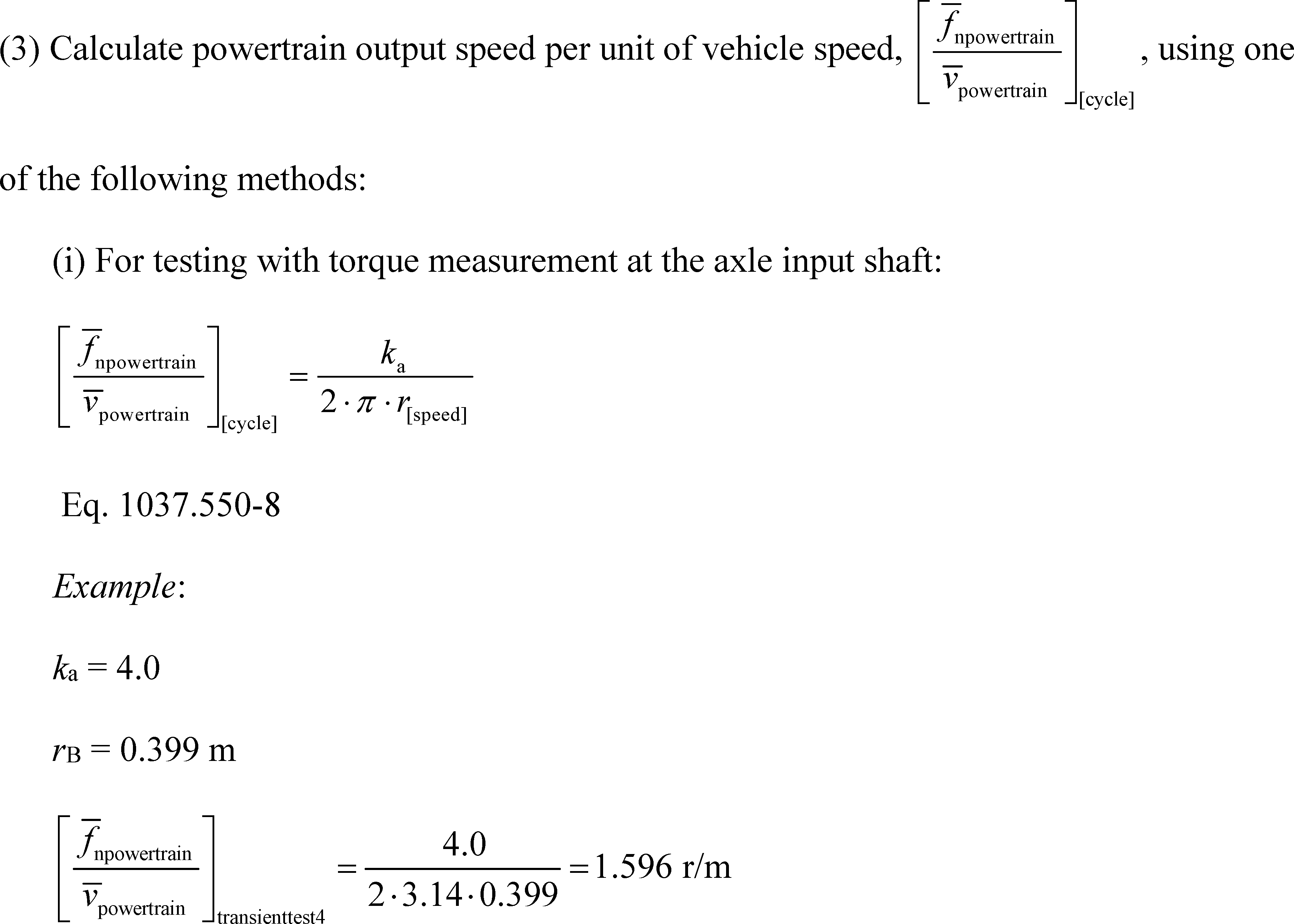
(ii) For testing with torque measurement at the wheel hubs, use Eq. 1037.550-8 setting ka equal to 1.
(iii) For testing with torque measurement at the engine's crankshaft:
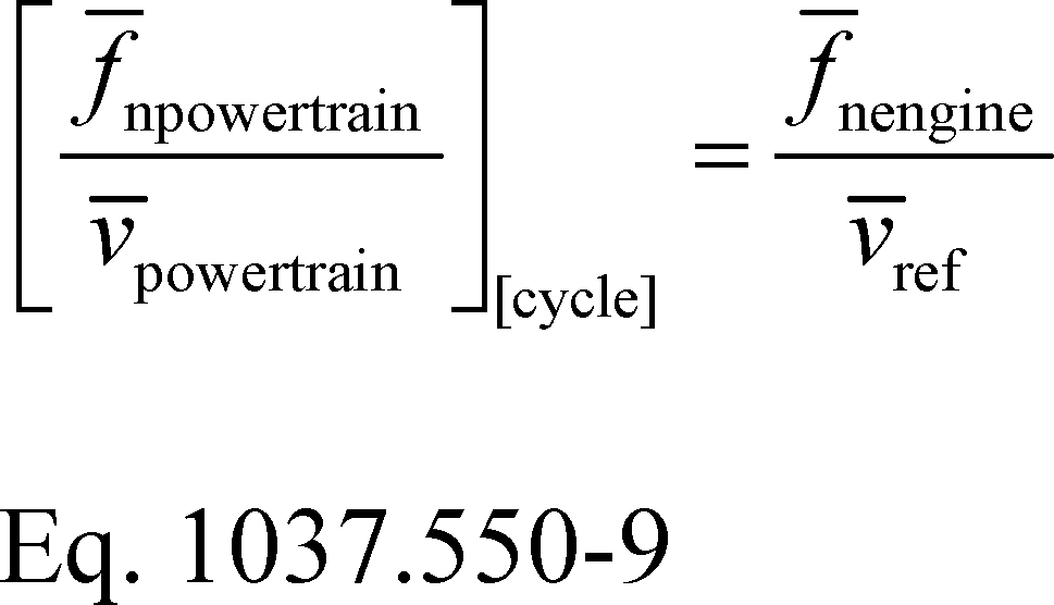
Where:
f̄nengine = average engine speed when vehicle speed is at or above 0.100 m/s.
v̄ref = average simulated vehicle speed at or above 0.100 m/s.
Example:
f̄nengine = 1870 r/min = 31.17 r/s
v̄ref = 19.06 m/s
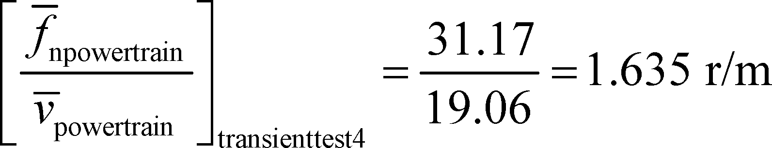
(4) Calculate positive work, W[cycle], as the work over the duty cycle at the axle input shaft, wheel hubs, or the engine's crankshaft, as applicable, when vehicle speed is at or above 0.100 m/s.
(5) Calculate engine idle speed, by taking the average engine speed measured during the transient cycle test while the vehicle speed is below 0.100 m/s.
(6) The following table illustrates the GEM data inputs corresponding to the different vehicle configurations for a given duty cycle:

[86 FR 34477, June 29, 2021]
§ 1037.551 Engine-based simulation of powertrain testing.
Section 1037.550 describes how to measure fuel consumption over specific duty cycles with an engine coupled to a transmission; § 1037.550(q) describes how to create equivalent duty cycles for repeating those same measurements with just the engine. This § 1037.551 describes how to perform this engine testing to simulate the powertrain test. These engine-based measurements may be used for confirmatory testing as described in § 1037.235, or for selective enforcement audits as described in § 1037.301, as long as the test engine's operation represents the engine operation observed in the powertrain test. If we use this approach for confirmatory testing, when making compliance determinations, we will consider the uncertainty associated with this approach relative to full powertrain testing. Use of this approach for engine SEAs is optional for engine manufacturers.
(a) Use the procedures of 40 CFR part 1065 to set up the engine, measure emissions, and record data. Measure individual parameters and emission constituents as described in this section. Measure NOX emissions for each sampling period in grams. You may perform these measurements using a NOX emission-measurement system that meets the requirements of 40 CFR part 1065, subpart J. Include these measured NOX values any time you report to us your greenhouse gas emissions or fuel consumption values from testing under this section. If a system malfunction prevents you from measuring NOX emissions during a test under this section but the test otherwise gives valid results, you may consider this a valid test and omit the NOX emission measurements; however, we may require you to repeat the test if we determine that you inappropriately voided the test with respect to NOX emission measurement. For hybrid powertrains, correct for the net energy change of the energy storage device as described in 40 CFR 1066.501.
(b) Operate the engine over the applicable engine duty cycles corresponding to the vehicle cycles specified in § 1037.510(a)(2) for powertrain testing over the applicable vehicle simulations described in § 1037.550(i). Warm up the engine to prepare for the transient test or one of the highway cruise cycles by operating it one time over one of the simulations of the corresponding duty cycle. Warm up the engine to prepare for the idle test by operating it over a simulation of the 65-mi/hr highway cruise cycle for 600 seconds. Within 60 seconds after concluding the warm up cycle, start emission sampling while the engine operates over the duty cycle. You may perform any number of test runs directly in succession once the engine is warmed up. Perform cycle validation as described in 40 CFR 1065.514 for engine speed, torque, and power.
(c) Calculate the mass of fuel consumed as described in § 1037.550(m) and (n). Correct each measured value for the test fuel's mass-specific net energy content as described in 40 CFR 1036.530. Use these corrected values to determine whether the engine's emission levels conform to the declared fuel-consumption rates from the powertrain test.
[81 FR 74048, Oct. 25, 2016, as amended at 86 FR 34483, June 29, 2021]
§ 1037.555 Special procedures for testing Phase 1 hybrid systems.
This section describes the procedure for simulating a chassis test with a pre-transmission or post-transmission hybrid system for A to B testing of Phase 1 vehicles. These procedures may also be used to perform A to B testing with non-hybrid systems. See § 1037.550 for Phase 2 hybrid systems.
(a) Set up the engine according to 40 CFR 1065.110 to account for work inputs and outputs and accessory work.
(b) Collect CO2 emissions while operating the system over the test cycles specified in § 1037.510(a)(1).
(c) Collect and measure emissions as described in 40 CFR part 1066. Calculate emission rates in grams per ton-mile without rounding. Determine values for A, B, C, and M for the vehicle being simulated as specified in 40 CFR part 1066. If you will apply an improvement factor or test results to multiple vehicle configurations, use values of A, B, C, M,ka, and r that represent the vehicle configuration with the smallest potential reduction in greenhouse gas emissions as a result of the hybrid capability.
(d) Calculate the transmission output shaft's angular speed target for the driver model, fnref,driver, from the linear speed associated with the vehicle cycle using the following equation:
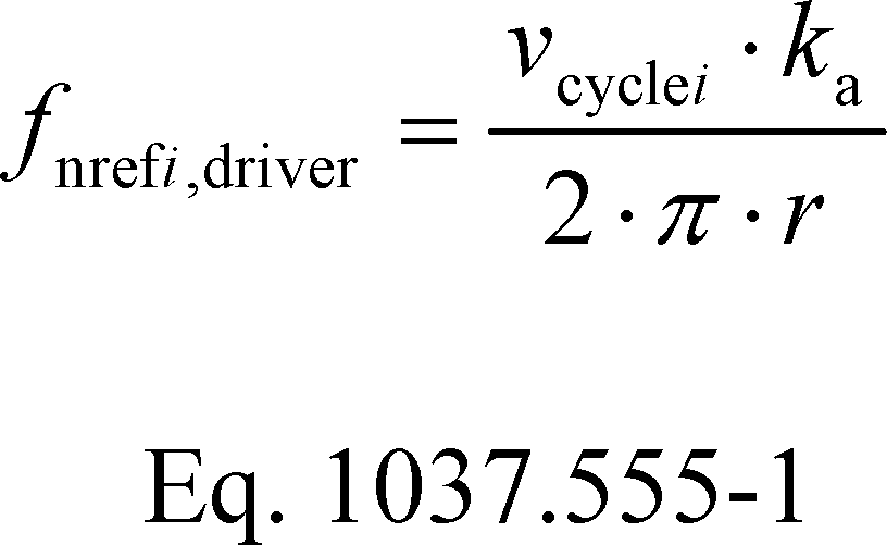
Where:
vcyclei = vehicle speed of the test cycle for each point, i, starting from i = 1.
ka = drive axle ratio, as declared by the manufacturer.
r = radius of the loaded tires, as declared by the manufacturer.
(e) Use speed control with a loop rate of at least 100 Hz to program the dynamometer to follow the test cycle, as follows:
(1) Calculate the transmission output shaft's angular speed target for the dynamometer, fnref,dyno, from the measured linear speed at the dynamometer rolls using the following equation:
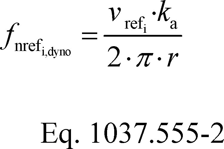
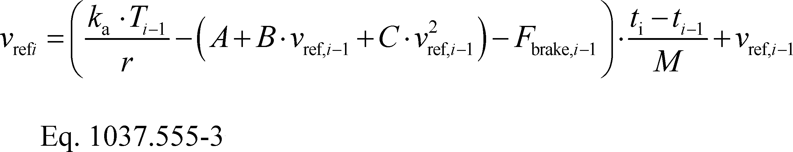
Where:
T = instantaneous measured torque at the transmission output shaft.
Fbrake = instantaneous brake force applied by the driver model to add force to slow down the vehicle.
t = elapsed time in the driving schedule as measured by the dynamometer, in seconds.
(2) For each test, validate the measured transmission output shaft's speed with the corresponding reference values according to 40 CFR 1065.514(e). You may delete points when the vehicle is stopped. Perform the validation based on speed values at the transmission output shaft. For steady-state tests (55 mi/hr and 65 mi/hr cruise), apply cycle-validation criteria by treating the sampling periods from the two tests as a continuous sampling period. Perform this validation based on the following parameters:
Table 1 of § 1037.555 - Statistical Criteria for Validating Duty Cycles
| Parameter | Speed control |
|---|---|
| Slope, a1 | 0.950 ≤ a1 ≤ 1.030. |
| Absolute value of intercept, |a0| | ≤2.0% of maximum test speed. |
| Standard error of the estimate, SEE | ≤5% of maximum test speed. |
| Coefficient of determination, r2 | ≥0.970. |
(f) Send a brake signal when operator demand is equal to zero and vehicle speed is greater than the reference vehicle speed from the test cycle. Set a delay before changing the brake state to prevent the brake signal from dithering, consistent with good engineering judgment.
(g) The driver model should be designed to follow the cycle as closely as possible and must meet the requirements of § 1037.510 for steady-state testing and 40 CFR 1066.430(e) for transient testing. The driver model should be designed so that the brake and throttle are not applied at the same time.
(h) Correct for the net energy change of the energy storage device as described in 40 CFR 1066.501.
(i) Follow the provisions of § 1037.510 to weight the cycle results and § 1037.615 to calculate improvement factors and benefits for advanced technologies for Phase 1 vehicles.
[81 FR 74048, Oct. 25, 2016, as amended at 86 FR 34483, June 29, 2021]
§ 1037.560 Axle efficiency test.
This section describes a procedure for mapping axle efficiency through a determination of axle power loss.
(a) You may establish axle power loss maps based on testing any number of axle configurations within an axle family as specified in § 1037.232. You may share data across a family of axle configurations, as long as you test the axle configuration with the lowest efficiency from the axle family; this will generally involve testing the axle with the highest axle ratio. For vehicles with tandem drive axles, always test each drive axle separately. For tandem axles that can be disconnected, test both single-drive and tandem axle configurations. This includes 4×4 axles where one of the axles is disconnectable. Alternatively, you may analytically derive power loss maps for untested configurations within the same axle family as described in paragraph (h) of this section.
(b) Prepare an axle assembly for testing as follows:
(1) Select an axle assembly with less than 500 hours of operation before testing. Assemble the axle in its housing, along with wheel ends and bearings.
(2) If you have a family of axle assemblies with different axle ratios, you may test multiple configurations using a common axle housing, wheel ends, and bearings.
(3) Install the axle assembly on the dynamometer with an input shaft angle perpendicular to the axle.
(i) For axle assemblies with or without a locking main differential, test the axle assembly using one of the following methods:
(A) Lock the main differential and test it with one electric motor on the input shaft and a second electric motor on the output side of the output shaft that has the speed-reduction gear attached to it.
(B) Test with the main differential unlocked and with one electric motor on the input shaft and electric motors on the output sides of each of the output shafts.
(ii) For drive-through tandem-axle setups, lock the longitudinal and inter-wheel differentials.
(4) Add gear oil according to the axle manufacturer's instructions. If the axle manufacturer specifies multiple gear oils, select the one with the highest viscosity at operating temperature. You may use a lower-viscosity gear oil if we approve that as critical emission-related maintenance under § 1037.125. Fill the gear oil to a level that represents in-use operation. You may use an external gear oil conditioning system, as long as it does not affect measured values.
(5) Install equipment for measuring the bulk temperature of the gear oil in the oil sump or a similar location. Report temperature to the nearest 0.1 °C.
(6) Break in the axle assembly using good engineering judgment. Maintain gear oil temperature at or below 100 °C throughout the break-in period.
(7) You may drain the gear oil following the break-in procedure and repeat the filling procedure described in paragraph (b)(4) of this section. We will follow your practice for our testing.
(c) Measure input and output speed and torque as described in 40 CFR 1065.210(b). You must use a speed-measurement system that meets an accuracy of ±0.05% of point. Use torque transducers that meet an accuracy requirement of ±1.0 N·m for unloaded test points and ±0.2% of the maximum tested axle input torque or output torque, respectively, for loaded test points. Calibrate and verify measurement instruments according to 40 CFR part 1065, subpart D. Command speed and torque at a minimum of 10 Hz, and record all data, including bulk oil temperature, as 1 Hz mean values.
(d) The test matrix consists of test points representing output torque and wheel speed values meeting the following specifications:
(1) Output torque includes both loaded and unloaded operation. For measurement involving unloaded output torque, also called spin loss testing, the wheel end is not connected to the dynamometer and is left to rotate freely; in this condition the input torque (to maintain constant wheel speed) equals the power loss. Test axles at a range of output torque values, as follows:
(i) 0, 500, 1000, 2000, 3000, and 4000 N·m for single drive axle applications for tractors and for vocational Heavy HDV with a single drive axle.
(ii) 0, 250, 500, 1000, 1500, and 2000 N·m for tractors, for vocational Heavy HDV with tandem drive axles, and for all vocational Light HDV or vocational Medium HDV.
(iii) You may exclude values that exceed your axle's maximum torque rating.
(2) Determine maximum wheel speed corresponding to a vehicle speed of 65 mi/hr based on the smallest tire (as determined using § 1037.520(c)(1)) that will be used with the axle. If you do not know the smallest tire size, you may use a default size of 650 r/mi. Use wheel angular speeds for testing that include 50 r/min and speeds in 100 r/min increments that encompass the maximum wheel speed (150, 250, etc.).
(3) You may test the axle assembly at additional speed and torque setpoints.
(e) Determine axle efficiency using the following procedure:
(1) Maintain ambient temperature between (15 and 35) °C throughout testing. Measure ambient temperature within 1.0 m of the axle assembly. Verify that critical axle settings (such as bearing preload, backlash, and oil sump level) are within specifications before and after testing.
(2) Maintain gear oil temperature at (81 to 83) °C. You may alternatively specify a lower range by shifting both temperatures down by the same amount. We will test your axle assembly using the same temperature range you specify for your testing. You may use an external gear oil conditioning system, as long as it does not affect measured values.
(3) Use good engineering judgment to warm up the axle assembly by operating it until the gear oil is within the specified temperature range.
(4) Stabilize operation at each point in the test matrix for at least 10 seconds, then measure the input torque, output torque, and wheel angular speed for at least 10 seconds. Record arithmetic mean values for all three parameters over the measurement period. Calculate power loss as described in paragraph (f) of this section based on these values for mean input torque, T̄in, mean output torque, T̄out, and mean wheel angular speed, f̄nwheel, at each test point.
(5) Perform the map sequence described in paragraph (e)(4) of this section three times. Remove torque from the input shaft and allow the axle to come to a full stop before each repeat measurement.
(6) You may need to perform additional testing at a given test point based on a calculation of a confidence interval to represent repeatability at a 95% confidence level for that test point. If the confidence limit is greater than 0.10% for loaded tests or greater than 0.05% for unloaded tests, perform another repeat of measurements at that test point and recalculate the repeatability for the whole set of test results. Continue testing until the confidence interval is at or below the specified values for all test points. Calculate a confidence interval representing the repeatability in establishing a 95% confidence level using the following equation:
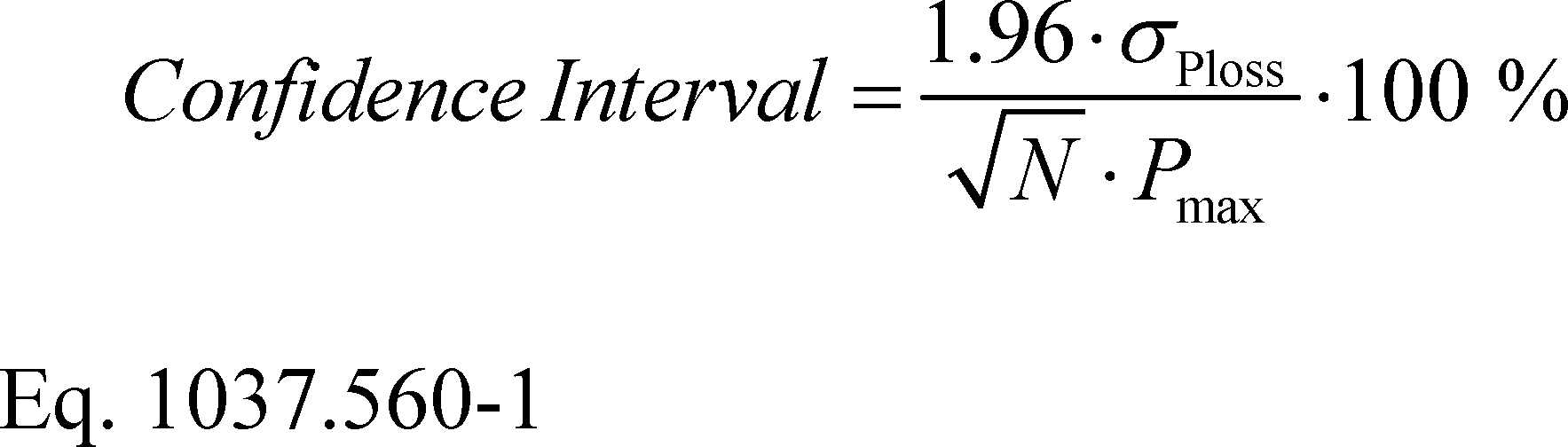
Where:
σPloss = standard deviation of power loss values at a given torque-speed setting (see 40 CFR 1065.602(c)).
N = number of repeat tests.
Pmax = maximum output torque setting from the test matrix.
Example:
σPloss = 0.1650 kW
N = 3
Pmax = 314.2000 kW

Confidence Interval = 0.0594%
(f) Calculate the mean power loss, Ploss, at each test point as follows:
(1) Calculate P̄loss for each measurement at each test point as follows:
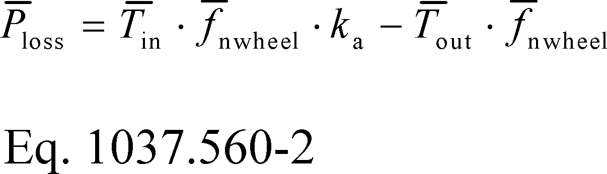
Where:
T̄in = mean input torque from paragraph (e)(4) of this section.
f̄nwheel = mean wheel angular speed from paragraph (e)(4) of this section in rad/s.
ka = drive axle ratio, expressed to at least the nearest 0.001.
T̄out = mean output torque from paragraph (e)(4) of this section. Let T̄out = 0 for all unloaded tests.
(2) Calculate Ploss as the mean power loss from all measurements at a given test point.
(3) The following example illustrates a calculation of Ploss:
T̄in,1 = 845.10 N·m
f̄nwheel,1 = 100.0 r/min = 10.472 rad/s
ka = 3.731
T̄out,1 = 3000.00 N·m
P̄loss,1 = 845.10 · 10.472 · 3.731 − 3000.00 · 10.472
P̄loss,1 = 1602.9 W = 1.6029 kW
P̄loss,2 = 1601.9 W = 1.6019 kW
P̄loss,3 = 1603.9 W = 1.6039 kW
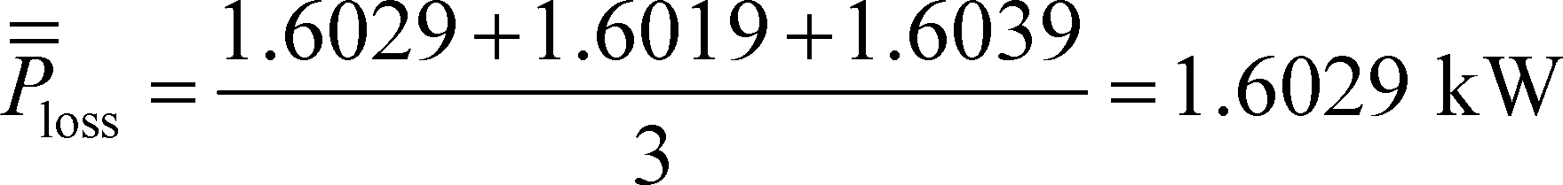
(g) Create a table with the mean power loss, Ploss, corresponding to each test point for input into GEM. Express wheel angular speed in r/min to one decimal place; express output torque in N·m to two decimal places; express power loss in kW to four decimal places.
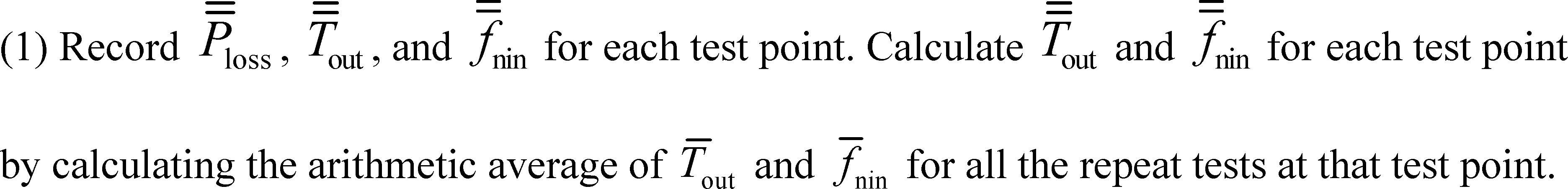
(2) Record declared mean power loss values at or above the corresponding value calculated in paragraph (f) of this section. Use good engineering judgment to select values that will be at or above the mean power loss values for your production axles. Vehicle manufacturers will use these declared mean power loss values for certification. For vehicles with tandem drive axles, the GEM input is the sum of the power loss and output torque from the individual axles. For vehicles with a disconnectable axle, GEM uses separate inputs for single and tandem drive axle configurations.
(h) You may analytically derive axle power loss maps for untested configurations within an axle family as follows:
(1) Test at least three axle assemblies within the same family representing at least the smallest axle ratio, the largest axle ratio, and an axle ratio closest to the arithmetic mean from the two other tested axle assemblies. Test each axle assembly as described in this section at the same speed and torque setpoints.
(2) Perform a second-order least-squares regression between declared power loss and axle ratio using each speed and torque setpoint described in paragraph (d) of this section for your tested axle assemblies. Use the declared power loss values from paragraph (g) of this section; however, for purposes of analytically deriving power loss maps under this paragraph (h), you must select declared values for the largest and smallest axle ratios in the axle family that are adjusted relative to the calculated values for mean power loss by the same multiplier. If the coefficent of the second-order term is negative, include testing from additional axle ratios, or increase your declared power loss for the largest and smallest axle ratios by the same multiplier as needed for the second-order term to become positive.
(3) Determine Ploss of untested axles for each speed and torque setpoint based on a linear relationship between your declared power loss and axle ratio as follows:
(i) Determine the slope of the correlation line by connecting the declared power loss values for the smallest and largest axle ratios.
(ii) Fix the intercept for the correlation line by shifting it upward as needed so all the declared power loss values are on the correlation line or below it. Note that for cases involving three tested axle assemblies, the correlation line will always include the declared power loss for the smallest and largest axle ratio.
(4) Select declared values of Ploss for untested configurations that are at or above the values you determined in paragraph (h)(3) of this section.
[86 FR 34484, June 29, 2021]
§ 1037.565 Transmission efficiency test.
This section describes a procedure for mapping transmission efficiency through a determination of transmission power loss.
(a) You may establish transmission power loss maps based on testing any number of transmission configurations within a transmission family as specified in § 1037.232. You may share data across any configurations within the family, as long as you test the transmission configuration with the lowest efficiency from the transmission family. Alternatively, you may ask us to approve analytically derived power loss maps for untested configurations within the same transmission family (see § 1037.235(h)).
(b) Prepare a transmission for testing as follows:
(1) Select a transmission with less than 500 hours of operation before testing.
(2) Mount the transmission to the dynamometer such that the geared shaft in the transmission is aligned with the input shaft from the dynamometer.
(3) Add transmission oil according to the transmission manufacturer's instructions. If the transmission manufacturer specifies multiple transmission oils, select the one with the highest viscosity at operating temperature. You may use a lower-viscosity transmission oil if we approve it as critical emission-related maintenance under § 1037.125. Fill the transmission oil to a level that represents in-use operation. You may use an external transmission oil conditioning system, as long as it does not affect measured values.
(4) Include any internal and external pumps for hydraulic fluid and lubricating oil in the test. Determine the work required to drive an external pump according to 40 CFR 1065.210.
(5) Install equipment for measuring the bulk temperature of the transmission oil in the oil sump or a similar location.
(6) If the transmission is equipped with a torque converter, lock it for all testing performed in this section.
(7) Break in the transmission using good engineering judgment. Maintain transmission oil temperature at (87 to 93) °C for automatic transmissions and transmissions having more than two friction clutches, and at (77 to 83) °C for all other transmissions. You may ask us to approve a different range of transmission oil temperatures if you have data showing that it better represents in-use operation.
(c) Measure input and output shaft speed and torque as described in 40 CFR 1065.210(b). You must use a speed measurement system that meets an accuracy of ±0.05% of point. Accuracy requirements for torque transducers depend on the highest loaded transmission input and output torque as described in paragraph (d)(2) of this section. Use torque transducers for torque input measurements that meet an accuracy requirement of ±0.2% of the highest loaded transmission input for loaded test points and ±0.1% of the highest loaded transmission input torque for unloaded test points. For torque output measurements, torque transducers must meet an accuracy requirement of ±0.2% of the highest loaded transmission output torque for each gear ratio. Calibrate and verify measurement instruments according to 40 CFR part 1065, subpart D. Command speed and torque at a minimum of 10 Hz, and record all data, including bulk oil temperature, at a minimum of 1 Hz mean values.
(d) Test the transmission at input shaft speeds and torque setpoints as described in this paragraph (d). You may exclude lower gears from testing; however, you must test all the gears above the highest excluded gear. GEM will use default values for any untested gears. The test matrix consists of test points representing transmission input shaft speeds and torque setpoints meeting the following specifications for each tested gear:
(1) Test at the following transmission input shaft speeds:
(i) 600.0 r/min or transmission input shaft speed when paired with the engine operating at idle.
(ii) The transmission's maximum rated input shaft speed. You may alternatively select a value representing the highest expected in-use transmission input shaft speed.
(iii) Three equally spaced intermediate speeds. The intermediate speed points may be adjusted to the nearest 50 or 100 r/min. You may test any number of additional speed setpoints to improve accuracy.
(2) Test at certain transmission input torque setpoints as follows:
(i) Include one unloaded (zero-torque) setpoint.
(ii) Include one loaded torque setpoint between 75% and 105% of the transmission's maximum rated input shaft torque. However, you may use a lower torque setpoint as needed to avoid exceeding dynamometer torque limits, as long as testing accurately represents in-use performance. If your loaded torque setpoint is below 75% of the transmission's maximum rated input shaft torque, you must demonstrate that the sum of time for all gears where demanded engine torque is between your maximum torque setpoint and 75% of the transmission's maximum rated input shaft torque is no more than 10% of the time for each vehicle drive cycle specified in subpart F of this part. This demonstration must be made available upon request.
(iii) You may test at any number of additional torque setpoints to improve accuracy.
(iv) Note that GEM calculates power loss between tested or default values by linear interpolation, except that GEM may extrapolate outside of measured values to account for testing at torque setpoints below 75% as specified in paragraph (d)(2)(ii) of this section.
(3) In the case of transmissions that automatically go into neutral when the vehicle is stopped, also perform tests at 600 r/min and 800 r/min with the transmission in neutral and the transmission output fixed at zero speed.
(e) Determine transmission efficiency using the following procedure:
(1) Maintain ambient temperature between (15 and 35) °C throughout testing. Measure ambient temperature within 1.0 m of the transmission.
(2) Maintain transmission oil temperature as described in paragraph (b)(7) of this section.
(3) Use good engineering judgment to warm up the transmission according to the transmission manufacturer's specifications.
(4) Perform unloaded transmission tests by disconnecting the transmission output shaft from the dynamometer and letting it rotate freely. If the transmission adjusts pump pressure based on whether the vehicle is moving or stopped, set up the transmission for unloaded tests to operate as if the vehicle is moving.
(5) For transmissions that have multiple configurations for a given gear ratio, such as dual-clutch transmissions that can pre-select an upshift or downshift, set the transmission to operate in the configuration with the greatest power loss. Alternatively, test in each configuration and use good engineering judgment to calculate a weighted power loss for each test point under this section based on field data that characterizes the degree of in-use operation in each configuration.
(6) For a selected gear, operate the transmission at one of the test points from paragraph (d) of this section for at least 10 seconds. Measure the speed and torque of the input and output shafts for at least 10 seconds. You may omit measurement of output shaft speeds if your transmission is configured to not allow slip. Calculate arithmetic mean values for mean input shaft torque, T̄in, mean output shaft torque, T̄out, mean input shaft speed, f̄nin, and mean output shaft speed, f̄nout, for each point in the test matrix for each test. Repeat this stabilization, measurement, and calculation for the other speed and torque setpoints from the test matrix for the selected gear in any sequence. Calculate power loss as described in paragraph (f) of this section based on mean speed and torque values at each test point.
(7) Repeat the procedure described in paragraph (e)(6) of this section for all gears, or for all gears down to a selected gear. This section refers to an “operating condition” to represent operation at a test point in a specific gear.
(8) Perform the test sequence described in paragraphs (e)(6) and (7) of this section three times. You may do this repeat testing at any given test point before you perform measurements for the whole test matrix. Remove torque from the transmission input shaft and bring the transmission to a complete stop before each repeat measurement.
(9) You may need to perform additional testing at a given operating condition based on a calculation of a confidence interval to represent repeatability at a 95% confidence level at that operating condition. If the confidence interval is greater than 0.10% for loaded tests or greater than 0.05% for unloaded tests, perform another measurement at that operating condition and recalculate the repeatability for the whole set of test results. Continue testing until the confidence interval is at or below the specified values for all operating conditions. As an alternative, for any operating condition that does not meet this repeatability criterion, you may determine a maximum power loss instead of calculating a mean power loss as described in paragraph (g) of this section. Calculate a confidence interval representing the repeatability in establishing a 95% confidence level using the following equation:

Where:
σPloss = standard deviation of power loss values at a given operating condition (see 40 CFR 1065.602(c)).
N = number of repeat tests for an operating condition.
Prated = the transmission's rated input power for a given gear. For testing in neutral, use the value of Prated for the top gear.
Example:
σPloss = 0.1200 kW
N = 3
Prated = 314.2000 kW

Confidence Interval = 0.0432%
(f) Calculate the mean power Ploss, at each operating condition as follows:
(1) Calculate P̄loss for each measurement at each operating condition as follows:
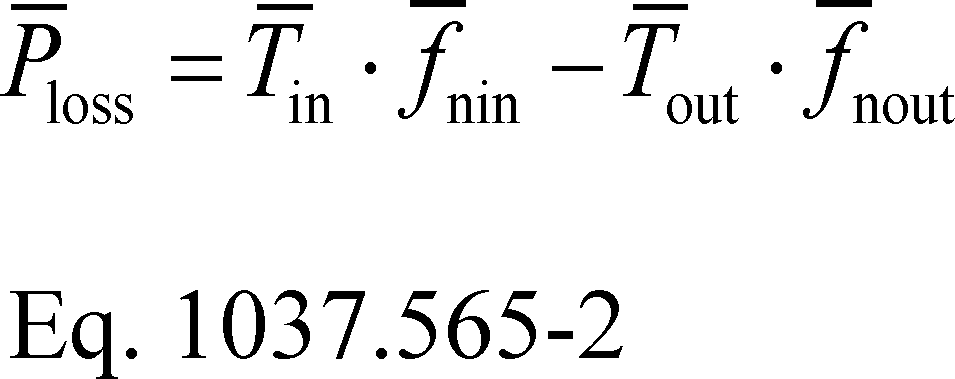
Where:
T̄in = mean input shaft torque from paragraph (e)(6) of this section.
f̄nin = mean input shaft speed from paragraph (e)(6) of this section in rad/s.
T̄out = mean output shaft torque from paragraph (e)(6) of this section. Let T̄out = 0 for all unloaded tests.
f̄nout = mean output shaft speed from paragraph (e)(6) of this section in rad/s. Let f̄nout = 0 for all tests with the transmission in neutral. See paragraph (f)(2) of this section for calculating f̄nout as a function of f̄nin instead of measuring f̄nout.
(2) For transmissions that are configured to not allow slip, you may calculate f̄nout based on the gear ratio using the following equation:

Where:
kg = transmission gear ratio, expressed to at least the nearest 0.001.
(3) Calculate Ploss as the mean power loss from all measurements at a given operating condition.
(4) The following example illustrates a calculation of Ploss:
T̄in,1 = 1000.0 N·m
f̄nin,1 = 1000 r/min = 104.72 rad/sec
T ̄out,1 = 2654.5 N·m
f̄nout,1 = 361.27 r/min = 37.832 rad/s
P̄loss,1 = 1000.0·104.72−2654.5·37.832
P̄loss,1 = 4295 W = 4.295 kW
P ̄loss,2 = 4285 W = 4.285 kW
P ̄loss,3 = 4292 W = 4.292 kW

(g) Create a table with the mean power loss, Ploss, corresponding to each operating condition for input into GEM. Also include power loss in neutral for each tested engine's speed, if applicable. Express transmission input speed in r/min to one decimal place; express input torque in N·m to two decimal places; express power loss in kW to four decimal places. Record the following values:

(2) For any operating condition not meeting the repeatability criterion in paragraph (e)(9) of this section, record the maximum value of P̄loss for that operating condition along with the corresponding values of T̄in and f̄nin.
(h) Record declared power loss values at or above the corresponding value calculated in paragraph (f) of this section. Use good engineering judgment to select values that will be at or above the mean power loss values for your production transmissions. Vehicle manufacturers will use these declared mean power loss values for certification.
[86 FR 34486, June 29, 2021; 86 FR 52833, Sept. 23, 2021]
§ 1037.570 Procedures to characterize torque converters.
GEM includes input values related to torque converters. This section describes a procedure for mapping a torque converter's capacity factors and torque ratios over a range of operating conditions. You may ask us to approve analytically derived input values based on this testing for additional untested configurations as described in § 1037.235(h).
(a) Prepare a torque converter for testing as follows:
(1) Select a torque converter with less than 500 hours of operation before the start of testing.
(2) If the torque converter has a locking feature, unlock it for all testing performed under this section. If the torque converter has a slipping lockup clutch, you may ask us to approve a different strategy based on data showing that it represents better in-use operation.
(3) Mount the torque converter with a transmission to the dynamometer in series or parallel arrangement or mount the torque converter without a transmission to represent a series configuration.
(4) Add transmission oil according to the torque converter manufacturer's instructions, with the following additional specifications:
(i) If the torque converter manufacturer specifies multiple transmission oils, select the one with the highest viscosity at operating temperature. You may use a lower-viscosity transmission oil if we approve that as critical emission-related maintenance under § 1037.125.
(ii) Fill the transmission oil to a level that represents in-use operation. If you are testing the torque converter without the transmission, keep output pressure and the flow rate of transmission oil into the torque converter within the torque converter manufacturer's limits.
(iii) You may use an external transmission oil conditioning system, as long as it does not affect measured values.
(5) Install equipment for measuring the bulk temperature of the transmission oil in the oil sump or a similar location and at the torque converter inlet. If the torque converter is tested without a transmission, measure the oil temperature at the torque converter inlet.
(6) Break in the torque converter and transmission (if applicable) using good engineering judgment. Maintain transmission oil temperature at (87 to 93) °C. You may ask us to approve a different range of transmission oil temperatures if you have data showing that it better represents in-use operation.
(b) Measure pump and turbine shaft speed and torque as described in 40 CFR 1065.210(b). You must use a speed measurement system that meets an accuracy of ±0.1% of point or ±1 r/min, whichever is greater. Use torque transducers that meet an accuracy of ±1.0% of the torque converter's maximum rated input and output torque, respectively. Calibrate and verify measurement instruments according to 40 CFR part 1065, subpart D. Command speed and torque at a minimum of 10 Hz. Record all speed and torque data at a minimum of 1 Hz mean values. Note that this section relies on the convention of describing the input shaft as the pump and the output shaft as the turbine shaft.
(c) Determine torque converter characteristics based on a test matrix using either constant input speed or constant input torque as follows:
(1) Constant input speed. Test at constant input speed as follows:
(i) Select a fixed pump speed, ƒnpum, between (1000 and 2000) r/min.
(ii) Test the torque converter at multiple speed ratios, v, in the range of v = 0.00 to v = 0.95. Use a step width of 0.10 for the range of v = 0.00 to 0.60 and 0.05 for the range of v = 0.60 to 0.95. Calculate speed ratio, v, as turbine shaft speed divided by pump speed.
(2) Constant input torque. Test at constant input torque as follows:
(i) Set the pump torque, Tpum, to a fixed positive value at ƒnpum = 1000 r/min with the torque converter's turbine shaft locked in a non-rotating state (i.e., turbine's speed, ntur, = 0 r/min).
(ii) Test the torque converter at multiple speed ratios, v, in the range of v = 0.00 up to a value of ƒntur that covers the usable range of v. Use a step width of 0.10 for the range of v = 0.00 to 0.60 and 0.05 for the range of v = 0.60 to 0.95.
(3) You may limit the maximum speed ratio to a value below 0.95 if you have data showing this better represents in-use operation. You must use the step widths defined in paragraph (c)(1) or (2) of this section and include the upper limit as a test point. If you choose a value less than 0.60, you must test at least seven evenly distributed points between v = 0 and your new upper speed ratio.
(d) Characterize the torque converter using the following procedure:
(1) Maintain ambient temperature between (15 and 35) °C throughout testing. Measure ambient temperature within 1.0 m of the torque converter.
(2) Maintain transmission oil temperature as described in paragraph (a)(6) of this section. You may use an external transmission oil conditioning system, as long as it does not affect measured values.
(3) Use good engineering judgment to warm up the torque converter according to the torque converter manufacturer's specifications.
(4) Test the torque converter at constant input speed or constant input torque as described in paragraph (c) of this section. Operate the torque converter at v = 0.00 for (5 to 60) seconds, then measure pump torque, turbine shaft torque, angular pump speed, angular turbine shaft speed, and the transmission oil temperature at the torque converter inlet for (5 to 15) seconds. Calculate arithmetic mean values for pump torque, T̄pum, turbine shaft torque, T̄tur, angular pump speed, f̄npum, and angular turbine shaft speed, f̄ntur, over the measurement period. Repeat this stabilization, measurement, and calculation for the other speed ratios from the test matrix in order of increasing speed ratio. Adjust the speed ratio by increasing the angular turbine shaft speed.
(5) Complete a test run by performing the test sequence described in paragraph (d)(4) of this section two times.
(6) Invalidate the test run if the difference between the pair of mean torque values for the repeat tests at any test point differ by more than ±1 N·m or by more than ±5% of the average of those two values. This paragraph (d)(6) applies separately for mean pump torque and mean turbine shaft torque at each test point.
(7) Invalidate the test run if any calculated value for mean angular pump speed does not stay within ±5 r/min of the speed setpoint or if any calculated value for mean pump torque does not stay within ±5 N·m of the torque setpoint.
(e) Calculate the mean torque ratio, l, at each tested speed ratio, v, as follows:
(1) Calculate at each tested speed ratio as follows:
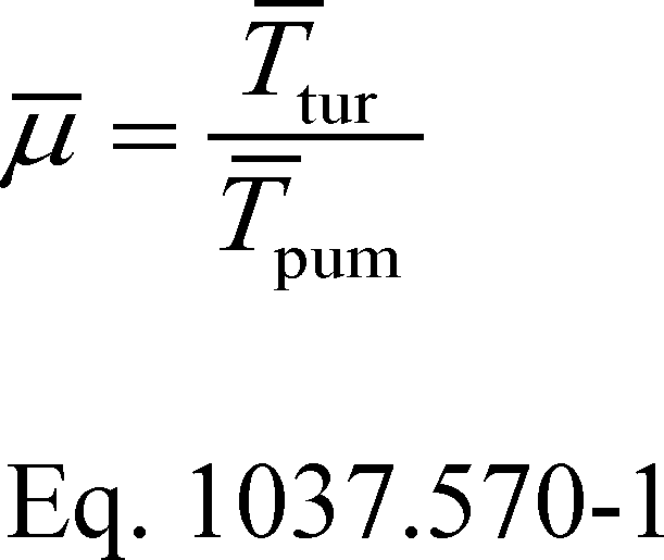
Where:
T̄tur = mean turbine shaft torque from paragraph (d)(4) of this section.
T̄pum = mean pump torque from paragraph (d)(4) of this section.
(2) Calculate l as the average of the two values of l at each tested speed ratio.
(3) The following example illustrates a calculation of l:
T ̄tur,v=0,1 = 332.4 N·m
T ̄pum,v=0,1 = 150.8 N·m
T ̄tur,v=0,2 = 333.6 N·m
T ̄pum,v=0,2 = 150.3 N·m
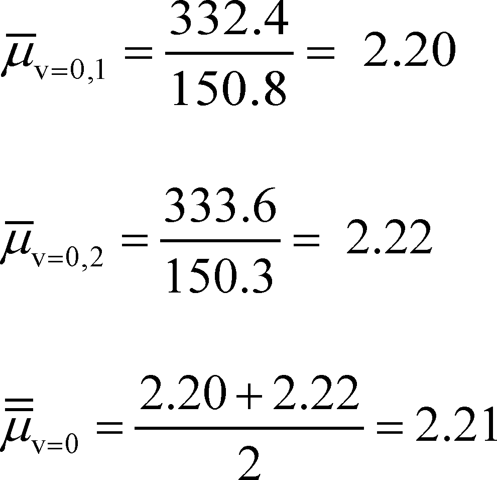
(f) Calculate the mean capacity factor, k, at each tested speed ratio, v, as follows:
(1) Calculate K̄ at each tested speed ratio as follows:
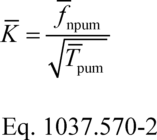
Where:
f̄npum = mean angular pump speed from paragraph (d)(4) of this section.
T̄pum = mean pump torque from paragraph (d)(4) of this section.
(2) Calculate k as the average of the two values of K̄ at each tested speed ratio.
(3) The following example illustrates a calculation of k:
f ̄npum,v=0,1 = f̄npum,v=0,2 = 1000.0 r/min
T ̄pum,v=0,1 = 150.8 N·m
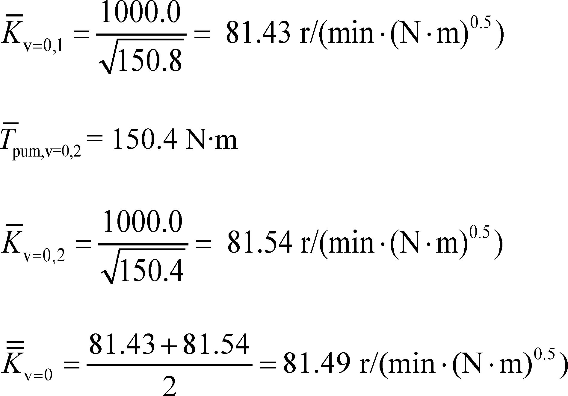
(g) Create a table of GEM inputs showing l and k at each tested speed ratio, v. Express l to two decimal places; express k to one decimal place; express v to two decimal places.
[86 FR 34488, June 29, 2021; 86 FR 52835, Sept. 23, 2021]
Subpart G - Special Compliance Provisions
§ 1037.601 General compliance provisions.
(a) Engine and vehicle manufacturers, as well as owners and operators of vehicles subject to the requirements of this part, and all other persons, must observe the provisions of this part, the applicable provisions of 40 CFR part 1068, and the applicable provisions of the Clean Air Act. The provisions of 40 CFR part 1068 apply for heavy-duty vehicles as specified in that part, subject to the provisions:
(1) Except as specifically allowed by this part or 40 CFR part 1068, it is a violation of § 1068.101(a)(1) to introduce into U.S. commerce a tractor or vocational vehicle containing an engine not certified to the applicable requirements of this part and 40 CFR part 86. Further, it is a violation to introduce into U.S. commerce a Phase 1 tractor containing an engine not certified for use in tractors; or to introduce into U.S. commerce a vocational vehicle containing a light heavy-duty or medium heavy-duty engine not certified for use in vocational vehicles. These prohibitions apply especially to the vehicle manufacturer. Note that this paragraph (a)(1) allows the use of Heavy heavy-duty tractor engines in vocational vehicles.
(2) The provisions of 40 CFR 1068.105(a) apply for vehicle manufacturers installing engines certified under 40 CFR part 1036 as further limited by this paragraph (a)(2). If new engine emission standards apply in a given model year, you may install normal inventories of engines from the preceding model year under the provisions of 40 CFR 1068.105(a) through March 31 of that year without our approval; you may not install such engines after March 31 of that year unless we approve it in advance. Installing such engines after March 31 without our prior approval is considered to be prohibited stockpiling of engines. In a written request for our approval, you must describe how your circumstances led you and your engine supplier to have normal inventories of engines that were not used up in the specified time frame. We will approve your request for up to three additional months to install engines under this paragraph (a)(2) if we determine that the excess inventory is a result of unforeseeable circumstances and should not be considered circumvention of emission standards. We will limit this approval to a certain number of engines consistent with your normal production and inventory practices. Note that 40 CFR 1068.105(a) allows vehicle manufacturers to use up only normal inventories of engines meeting less stringent standards; if, for example, a vehicle manufacturer's normal practice is to receive a shipment of engines every two weeks, it will deplete its potential to install previous-tier engines under this paragraph (a)(2) well before March 31 in the year that new standards apply.
(3) The exemption provisions of 40 CFR 1068.201 through 1068.230, 1068.240, and 1068.260 through 265 apply for heavy-duty motor vehicles. Other exemption provisions, which are specific to nonroad engines, do not apply for heavy-duty vehicles or heavy-duty engines.
(4) The tampering prohibition in 40 CFR 1068.101(b)(1) applies for alternative fuel conversions as specified in 40 CFR part 85, subpart F.
(5) The warranty-related prohibitions in section 203(a)(4) of the Act (42 U.S.C. 7522(a)(4)) apply to manufacturers of new heavy-duty highway vehicles in addition to the prohibitions described in 40 CFR 1068.101(b)(6). We may assess a civil penalty up to $44,539 for each engine or vehicle in violation.
(6) A vehicle manufacturer that completes assembly of a vehicle at two or more facilities may ask to use as the date of manufacture for that vehicle the date on which manufacturing is completed at the place of main assembly, consistent with provisions of 49 CFR 567.4. Note that such staged assembly is subject to the corresponding provisions of 40 CFR 1068.260. Include your request in your application for certification, along with a summary of your staged-assembly process. You may ask to apply this allowance to some or all of the vehicles in your vehicle family. Our approval is effective when we grant your certificate. We will not approve your request if we determine that you intend to use this allowance to circumvent the intent of this part.
(7) The provisions for selective enforcement audits apply as described in 40 CFR part 1068, subpart E, and subpart D of this part.
(b) Vehicles exempted from the applicable standards of 40 CFR part 86 other than glider vehicles are exempt from the standards of this part without request. Similarly, vehicles other than glider vehicles are exempt without request if the installed engine is exempted from the applicable standards in 40 CFR part 86.
(c) The prohibitions of 40 CFR 1068.101 apply for vehicles subject to the requirements of this part. The actions prohibited under this provision include the introduction into U.S. commerce of a complete or incomplete vehicle subject to the standards of this part where the vehicle is not covered by a valid certificate of conformity or exemption.
(d) The emergency vehicle field modification provisions of 40 CFR 85.1716 apply with respect to the standards of this part.
(e) Under § 1037.801, certain vehicles are considered to be new vehicles when they are imported into the United States, even if they have previously been used outside the country. Independent Commercial Importers may use the provisions of 40 CFR part 85, subpart P, and 40 CFR 85.1706(b) to receive a certificate of conformity for engines and vehicles meeting all the requirements of 40 CFR part 1036 and this part 1037.
(f) Standards apply to multi-fuel vehicles as described for engines in 40 CFR 1036.601(d).
[81 FR 74048, Oct. 25, 2016, as amended at 86 FR 34489, June 29, 2021]
§ 1037.605 Installing engines certified to alternate standards for specialty vehicles.
(a) General provisions. This section allows vehicle manufacturers to introduce into U.S. commerce certain new motor vehicles using engines certified to alternate emission standards specified in 40 CFR part 86 for motor vehicle engines used in specialty vehicles. You may not install an engine certified to these alternate standards if there is an engine certified to the full set of requirements of 40 CFR part 86 that has the appropriate physical and performance characteristics to power the vehicle. Note that, although these alternate emission standards are mostly equivalent to standards that apply for nonroad engines under 40 CFR part 1039 or 1048, they are specific to motor vehicle engines. The alternate standards for compression-ignition engines at or above 56 kW are described in 40 CFR 86.007-11(g); the alternate standards for spark-ignition engines are described in 40 CFR 86.008-10(g). The provisions of this section apply for the following types of specialty vehicles:
(1) All-terrain motor vehicles with portal axles (i.e., axles that are offset from the corresponding wheel centerline by a gear assembly) or any axle configuration involving gear reduction such that the wheels rotate more slowly than the axle.
(2) Amphibious vehicles.
(3) Vehicles with maximum speed at or below 45 miles per hour. If your vehicle is speed-limited to meet this specification by reducing maximum speed below what is otherwise possible, this speed limitation must be programmed into the engine or vehicle's electronic control module in a way that is tamper-proof. If your vehicles are not inherently limited to a maximum speed at or below 45 miles per hour, they may qualify under this paragraph (a)(3) only if we approve your design to limit maximum speed as being tamper-proof in advance.
(4) Through model year 2027, vehicles with a hybrid powertrain in which the engine provides energy for the Rechargeable Energy Storage System.
(b) Notification and reporting requirements. Send the Designated Compliance Officer written notification describing your plans before using the provisions of this section. In addition, by February 28 of each calendar year (or less often if we tell you), send the Designated Compliance Officer a report with all the following information:
(1) Identify your full corporate name, address, and telephone number.
(2) List the vehicle models for which you used this exemption in the previous year and identify the engine manufacturer and engine model for each vehicle model. Also identify the total number of vehicles produced in the previous year.
(c) Production limits. You may produce up to 1,000 hybrid vehicles in a given model year through model year 2027, and up to 200 of each type of vehicle identified in paragraph (a)(1) through (3) of this section in a given model year. This includes vehicles produced by affiliated companies. If you exceed this limit, the number of vehicles that exceed the limit for the model year will not be covered by a valid certificate of conformity. For the purpose of this paragraph (c), we will count all vehicles labeled or otherwise identified as exempt under this section.
(d) Vehicle standards. The vehicle standards of this part apply as follows for these vehicles:
(1) Vehicles qualifying under paragraphs (a)(1) through (3) of this section are subject to evaporative emission standards of § 1037.103, but are exempt from the other requirements of this part, except as specified in this section and in § 1037.601. These vehicles must include a label as specified in § 1037.135(a) with the information from § 1037.135(c)(1) and (2) and the following statement: “THIS VEHICLE IS EXEMPT FROM GREENHOUSE GAS STANDARDS UNDER 40 CFR 1037.605.”
(2) Hybrid vehicles using the provisions of this section remain subject to the vehicle standards and all other requirements of this part 1037. For example, you may need to use GEM in conjunction with powertrain testing to demonstrate compliance with emission standards under subpart B of this part.
§ 1037.610 Vehicles with off-cycle technologies.
(a) You may ask us to apply the provisions of this section for CO2 emission reductions resulting from vehicle technologies that were not in common use with heavy-duty vehicles before model year 2010 that are not reflected in GEM. While you are not required to prove that such technologies were not in common use with heavy-duty vehicles before model year 2010, we will not approve your request if we determine that they do not qualify. These may be described as off-cycle or innovative technologies. You may apply these provisions for CO2 emission reductions reflected in the specified test procedures if they are not reflected in GEM, except as allowed under paragraph (g) of this section. We will apply these provisions only for technologies that will result in measurable, demonstrable, and verifiable real-world CO2 emission reductions.
(b) The provisions of this section may be applied as either an improvement factor or as a separate credit, consistent with good engineering judgment. Note that the term “credit” in this section describes an additive adjustment to emission rates and is not equivalent to an emission credit in the ABT program of subpart H of this part. We recommend that you base your credit/adjustment on A to B testing of pairs of vehicles differing only with respect to the technology in question.
(1) Calculate improvement factors as the ratio of in-use emissions with the technology divided by the in-use emissions without the technology. Use the improvement-factor approach where good engineering judgment indicates that the actual benefit will be proportional to emissions measured over the test procedures specified in this part.
(2) Calculate separate credits (g/ton-mile) based on the difference between the in-use emission rate with the technology and the in-use emission rate without the technology. Subtract this value from your GEM result and use this adjusted value to determine your FEL. Use the separate-credit approach where good engineering judgment indicates that the actual benefit will not be proportional to emissions measured over the test procedures specified in this part.
(3) We may require you to discount or otherwise adjust your improvement factor or credit to account for uncertainty or other relevant factors.
(c) You may perform A to B testing by measuring emissions from the vehicles during chassis testing or from in-use on-road testing. You may also ask to use modified powertrain testing. If you use on-road testing, we recommend that you test according to SAE J1321, Fuel Consumption Test Procedure—Type II, revised February 2012, or SAE J1526, SAE Fuel Consumption Test Procedure (Engineering Method), Revised September 2015 (see § 1037.810 for information on availability of SAE standards), subject to the following provisions:
(1) The minimum route distance is 100 miles.
(2) The route selected must be representative in terms of grade. We will take into account published and relevant research in determining whether the grade is representative.
(3) Control vehicle speed over the route to be representative of the drive-cycle weighting adopted for each regulatory subcategory, as specified in § 1037.510(c), or apply a correction to account for the appropriate weighting. For example, if the route selected for an evaluation of a combination tractor with a sleeper cab contains only interstate driving at 65 mi/hr, the improvement factor would apply only to 86 percent of the weighted result.
(4) The ambient air temperature must be between (5 and 35) °C, unless the technology requires other temperatures for demonstration.
(5) We may allow you to use a Portable Emissions Measurement System (PEMS) device for measuring CO2 emissions during the on-road testing.
(d) Send your request to the Designated Compliance Officer. We recommend that you do not begin collecting test data (for submission to EPA) before contacting us. For technologies for which the engine manufacturer could also claim credits (such as transmissions in certain circumstances), we may require you to include a letter from the engine manufacturer stating that it will not seek credits for the same technology. Your request must contain the following items:
(1) A detailed description of the off-cycle technology and how it functions to reduce CO2 emissions under conditions not represented on the duty cycles required for certification.
(2) A list of the vehicle configurations that will be equipped with the technology.
(3) A detailed description and justification of the selected test vehicles.
(4) All testing and simulation data required under this section, plus any other data you have considered in your analysis. You may ask for our preliminary approval of your test plan under § 1037.210.
(5) A complete description of the methodology used to estimate the off-cycle benefit of the technology and all supporting data, including vehicle testing and in-use activity data. Also include a statement regarding your recommendation for applying the provisions of this section for the given technology as an improvement factor or a credit.
(6) An estimate of the off-cycle benefit by vehicle model, and the fleetwide benefit based on projected sales of vehicle models equipped with the technology.
(7) A demonstration of the in-use durability of the off-cycle technology, based on any available engineering analysis or durability testing data (either by testing components or whole vehicles).
(8) A recommended method for auditing production vehicles consistent with the intent of 40 CFR part 1068, subpart E. We may approve your recommended method or specify a different method.
(e) We may seek public comment on your request, consistent with the provisions of 40 CFR 86.1866. However, we will generally not seek public comment on credits or adjustments based on A to B chassis testing performed according to the duty-cycle testing requirements of this part or in-use testing performed according to paragraph (c) of this section.
(f) We may approve an improvement factor or credit for any configuration that is properly represented by your testing.
(1) For model years before 2021, you may continue to use an approved improvement factor or credit for any appropriate vehicle families in future model years through 2020.
(2) For model years 2021 and later, you may not rely on an approval for model years before 2021. You must separately request our approval before applying an improvement factor or credit under this section for Phase 2 vehicles, even if we approved an improvement factor or credit for similar vehicle models before model year 2021. Note that Phase 2 approval may carry over for multiple years.
(g) You normally may not calculate off-cycle credits or improvement factors under this section for technologies represented by GEM, but we may allow you to do so by averaging multiple GEM runs for special technologies for which a single GEM run cannot accurately reflect in-use performance. For example, if you use an idle-reduction technology that is effective 80 percent of the time, we may allow you to run GEM with the technology active and with it inactive, and then apply an 80% weighting factor to calculate the off-cycle credit or improvement factor. You may need to perform testing to establish proper weighting factors or otherwise quantify the benefits of the special technologies.
§ 1037.615 Advanced technologies.
(a) This section applies in Phase 1 for hybrid vehicles with regenerative braking, vehicles equipped with Rankine-cycle engines, electric vehicles, and fuel cell vehicles, and in Phase 2 through model year 2027 for plug-in hybrid electric vehicles, electric vehicles, and fuel cell vehicles. You may not generate credits for Phase 1 engine technologies for which the engines generate credits under 40 CFR part 1036.
(b) Generate Phase 1 advanced-technology credits for vehicles other than electric vehicles as follows:
(1) Measure the effectiveness of the advanced system by chassis-testing a vehicle equipped with the advanced system and an equivalent conventional vehicle, or by testing the hybrid systems and the equivalent non-hybrid systems as described in § 1037.555. Test the vehicles as specified in subpart F of this part. For purposes of this paragraph (b), a conventional vehicle is considered to be equivalent if it has the same footprint (as defined in 40 CFR 86.1803), vehicle service class, aerodynamic drag, and other relevant factors not directly related to the hybrid powertrain. If you use § 1037.540 to quantify the benefits of a hybrid system for PTO operation, the conventional vehicle must have the same number of PTO circuits and have equivalent PTO power. If you do not produce an equivalent vehicle, you may create and test a prototype equivalent vehicle. The conventional vehicle is considered Vehicle A and the advanced vehicle is considered Vehicle B. We may specify an alternate cycle if your vehicle includes a power take-off.
(2) Calculate an improvement factor and g/ton-mile benefit using the following equations and parameters:
(i) Improvement Factor = [(Emission Rate A)−(Emission Rate B)]/(Emission Rate A).
(ii) g/ton-mile benefit = Improvement Factor × (GEM Result B).
(iii) Emission Rates A and B are the g/ton-mile CO2 emission rates of the conventional and advanced vehicles, respectively, as measured under the test procedures specified in this section. GEM Result B is the g/ton-mile CO2 emission rate resulting from emission modeling of the advanced vehicle as specified in § 1037.520.
(3) If you apply an improvement factor to multiple vehicle configurations using the same advanced technology, use the vehicle configuration with the smallest potential reduction in greenhouse gas emissions resulting from the hybrid capability.
(4) Use the equations of § 1037.705 to convert the g/ton-mile benefit to emission credits (in Mg). Use the g/ton-mile benefit in place of the (Std-FEL) term.
(c) See § 1037.540 for special testing provisions related to Phase 1 vehicles equipped with hybrid power take-off units.
(d) For Phase 2 plug-in hybrid electric vehicles and for fuel cells powered by any fuel other than hydrogen, calculate CO2 credits using an FEL based on emission measurements from powertrain testing. Phase 2 advanced-technology credits do not apply for hybrid vehicles that have no plug-in capability.
(e) You may use an engineering analysis to calculate an improvement factor for fuel cell vehicles based on measured emissions from the fuel cell vehicle.
(f) For electric vehicles and for fuel cells powered by hydrogen, calculate CO2 credits using an FEL of 0 g/ton-mile.
(g) As specified in subpart H of this part, advanced-technology credits generated from Phase 1 vehicles under this section may be used under this part 1037 outside of the averaging set in which they were generated, or they may be used under 40 CFR 86.1819 or 40 CFR part 1036. Advanced-technology credits generated from Phase 2 vehicles are subject to all the averaging-set restrictions that apply to other emission credits.
(h) You may certify using both provisions of this section and the off-cycle technology provisions of § 1037.610, provided you do not double count emission benefits.
[81 FR 74048, Oct. 25, 2016, as amended at 86 FR 34490, June 29, 2021]
§ 1037.620 Responsibilities for multiple manufacturers.
This section describes certain circumstances in which multiple manufacturers share responsibilities for vehicles they produce together. This section does not limit responsibilities that apply under the Act or these regulations for anyone meeting the definition of “manufacturer” in § 1037.801. Note that the definition of manufacturer is broad and can include persons not commercially considered to be manufacturers.
(a) The following provisions apply when there are multiple persons meeting the definition of manufacturer in § 1037.801:
(1) Each person meeting the definition of manufacturer must comply with the requirements of this part that apply to manufacturers. However, if one person complies with a specific requirement for a given vehicle, then all manufacturers are deemed to have complied with that specific requirement.
(2) We will apply the requirements of subparts C and D of this part to the manufacturer that obtains the certificate of conformity for the vehicle. Other manufacturers are required to comply with the requirements of subparts C and D of this part only when notified by us. In our notification, we will specify a reasonable time period in which you need to comply with the requirements identified in the notice. See § 1037.601 for the applicability of 40 CFR part 1068 to these other manufacturers and remanufacturers.
(b) The provisions of § 1037.621, including delegated assembly, apply for certifying manufacturers that rely on other manufacturers to finish assembly in a certified configuration. The provisions of § 1037.622 generally apply for manufacturers that ship vehicles subject to the requirements of this part to a certifying secondary vehicle manufacturer. The provisions of § 1037.622 also apply to the secondary vehicle manufacturer. If you hold the certificate of conformity for a vehicle only with respect to exhaust or evaporative emissions, and a different company holds the other certificate of conformity for that vehicle, the provisions of § 1037.621 apply with respect to the certified configuration as described in your application for certification, and the provisions of § 1037.622 apply with respect to the certified configuration as described in the other manufacturer's application for certification.
(c) Manufacturers of aerodynamic devices may perform the aerodynamic testing described in § 1037.526 to quantify ΔCdA values for trailers and submit that data to EPA verification under § 1037.211. Trailer manufacturers may use such verified data to establish input parameters for certifying their trailers. Both device manufacturers and trailer manufacturers are subject to 40 CFR part 1068, including the recall provisions described in 40 CFR part 1068, subpart F.
(d) Component manufacturers (such as tire manufacturers) providing test data to certifying vehicle manufacturers are responsible as follows for test components and emission test results provided to vehicle manufacturers for the purpose of certification under this part:
(1) Such test results are deemed under § 1037.825 to be submissions to EPA. This means that you may be subject to criminal penalties under 18 U.S.C. 1001 if you knowingly submit false test results to the certifying manufacturer.
(2) You may not cause a vehicle manufacturer to violate the regulations by rendering inaccurate emission test results you provide (or emission test results from testing of test components you provide) to the vehicle manufacturer (see 40 CFR 1068.101(c)).
(3) Your provision of test components and/or emission test results to vehicle manufacturers for the purpose of certifying under this part are deemed to be an agreement to provide components to EPA for confirmatory testing under § 1037.235.
(e) Component manufacturers may contractually agree to process emission warranty claims on behalf of the certifying manufacturer with respect to those components, as follows:
(1) Your fulfillment of the warranty requirements of this part is deemed to fulfill the vehicle manufacturer's warranty obligations under this part with respect to components covered by your warranty.
(2) You may not cause a vehicle manufacturer to violate the regulations by failing to fulfill the emission warranty requirements that you contractually agreed to fulfill (see 40 CFR 1068.101(c)).
(f) We may require component manufacturers to provide information or take other actions under 42 U.S.C. 7542. For example, we may require component manufacturers to test components they produce.
§ 1037.621 Delegated assembly.
(a) This section describes provisions that allow certificate holders to sell or ship vehicles that are missing certain emission-related components if those components will be installed by a secondary vehicle manufacturer. Paragraph (g) of this section similarly describes how dealers and distributors may modify new vehicles with your advance approval. (Note: See § 1037.622 for provisions related to manufacturers introducing into U.S. commerce partially complete vehicles for which a secondary vehicle manufacturer holds the certificate of conformity.)
(b) You do not need an exemption to ship a vehicle that does not include installation or assembly of certain emission-related components if those components are shipped along with the vehicle. For example, you may generally ship fuel tanks and aerodynamic devices along with vehicles rather than installing them on the vehicle before shipment. We may require you to describe how you plan to use this provision.
(c) You may ask us at the time of certification for an exemption to allow you to ship your vehicles without emission-related components. If we allow this, you must provide emission-related installation instructions as specified in § 1037.130. You must follow delegated-assembly requirements in 40 CFR 1068.261 if you rely on secondary vehicle manufacturers to install certain technologies or components as specified in paragraph (d) of this section. For other technologies or components, we may specify conditions that we determine are needed to ensure that shipping the vehicle without such components will not result in the vehicle being operated outside of its certified configuration; this may include a requirement to comply with the delegated-assembly provisions in paragraph (d) of this section. We may consider your past performance when we specify the conditions that apply.
(d) Delegated-assembly provisions apply as specified in this paragraph (d) if the certifying vehicle manufacturer relies on a secondary vehicle manufacturer to procure and install auxiliary power units, aerodynamic devices, hybrid components (for powertrain or power take-off), or natural gas fuel tanks. These provisions do not apply for other systems or components, such as air conditioning lines and fittings, except as specified in paragraph (c) of this section. Apply the provisions of 40 CFR 1068.261, with the following exceptions and clarifications:
(1) Understand references to “engines” to refer to vehicles.
(2) Understand references to “aftertreatment components” to refer to any relevant emission-related components under this paragraph (d).
(3) Understand “equipment manufacturers” to be secondary vehicle manufacturers.
(4) The provisions of 40 CFR 1068.261(b), (c)(7), (d), and (e) do not apply. Accordingly, the provisions of 40 CFR 1068.261(c) apply regardless of pricing arrangements.
(e) Secondary vehicle manufacturers must follow the engine manufacturer's emission-related installation instructions. Not meeting the manufacturer's emission-related installation instructions is a violation of one or more of the prohibitions of § 1068.101. We may also require secondary vehicle manufacturers to recall defective vehicles under 40 CFR 1068.505 if we determine that their manufacturing practices caused vehicles to not conform to the regulations. Secondary vehicle manufacturers may be required to meet additional requirements if the certifying vehicle manufacturer delegates final assembly of emission controls as described in paragraph (d) of this section.
(f) Except as allowed by § 1037.622, the provisions of this section apply to manufacturers for glider kits they produce. Note that under § 1037.620, glider kit manufacturers are generally presumed to be responsible (in whole or in part) for compliance with respect to vehicles produced from their glider kits, even if a secondary vehicle manufacturer holds the certificate under § 1037.622.
(g) We may allow certifying vehicle manufacturers to authorize dealers or distributors to reconfigure/recalibrate vehicles after the vehicles have been introduced into commerce if they have not yet been delivered to the ultimate purchaser as follows:
(1) This allowance is limited to changes from one certified configuration to another, as noted in the following examples:
(i) If your vehicle family includes certified configurations with different axle ratios, you may authorize changing from one certified axle ratio to another.
(ii) You may authorize adding a certified APU to a tractor.
(2) Your final ABT report must accurately describe the vehicle's certified configuration as delivered to the ultimate purchaser. This means that the allowance no longer applies after you submit the final ABT report.
(3) The vehicle label must accurately reflect the final vehicle configuration.
(4) You must keep records to document modifications under this paragraph (g).
(5) Dealers and distributors must keep a record of your authorizing instructions. Dealers and distributors that fail to follow your instructions or otherwise make unauthorized changes may be committing a tampering violation as described in 40 CFR 1068.105(b).
[81 FR 74048, Oct. 25, 2016, as amended at 86 FR 34490, June 29, 2021]
§ 1037.622 Shipment of partially complete vehicles to secondary vehicle manufacturers.
This section specifies how manufacturers may introduce partially complete vehicles into U.S. commerce (or in the case of certain custom vehicles, introduce complete vehicles into U.S. commerce for modification by a small manufacturer). The provisions of this section are generally not intended for trailers, but they may apply in unusual circumstances, such as when a secondary vehicle manufacturer will modify a trailer in a way that makes it exempt. The provisions of this section are intended to accommodate normal business practices without compromising the effectiveness of certified emission controls. You may not use the provisions of this section to circumvent the intent of this part. For vehicles subject to both exhaust GHG and evaporative standards, the provisions of this part apply separately for each certificate.
(a) The provisions of this section allow manufacturers to ship partially complete vehicles to secondary vehicle manufacturers or otherwise introduce them into U.S. commerce in the following circumstances:
(1) Certified vehicles. Manufacturers may introduce partially complete tractors into U.S. commerce if they are covered by certificates of conformity and are in certified configurations. See § 1037.621 for vehicles not yet in a certified configuration when introduced into U.S. commerce.
(2) Uncertified vehicles that will be certified by secondary vehicle manufacturers. Manufacturers may introduce into U.S. commerce partially complete vehicles for which they do not hold the required certificate of conformity only as allowed by paragraph (b) of this section; however, the requirements of this section do not apply for tractors or vocational vehicles with a date of manufacture before January 1, 2022, that are produced by a secondary vehicle manufacturer if they are excluded from the standards of this part under § 1037.150(c).
(3) Exempted vehicles. Manufacturers may introduce into U.S. commerce partially complete vehicles without a certificate of conformity if the vehicles are exempt under this part or under 40 CFR part 1068. This may involve the secondary vehicle manufacturer qualifying for the exemption.
(4) Small manufacturers modifying certified tractors. Small manufacturers that build custom sleeper cabs or natural gas-fueled tractors may modify complete or incomplete vehicles certified as tractors, as specified by paragraph (d) of this section.
(b) The provisions of this paragraph (b) generally apply where the secondary vehicle manufacturer has substantial control over the design and assembly of emission controls. They also apply where a secondary vehicle manufacturer qualifies for a permanent exemption. In unusual circumstances we may allow other secondary vehicle manufacturers to use these provisions. In determining whether a manufacturer has substantial control over the design and assembly of emission controls, we would consider the degree to which the secondary vehicle manufacturer would be able to ensure that the engine and vehicle will conform to the regulations in their final configurations.
(1) A secondary vehicle manufacturer may finish assembly of partially complete vehicles in the following cases:
(i) It obtains a vehicle that is not fully assembled with the intent to manufacture a complete vehicle in a certified or exempted configuration. For example, this would apply where a glider vehicle assembler holds a certificate that allows the assembler to produce certified glider vehicles from glider kits.
(ii) It obtains a vehicle with the intent to modify it to a certified configuration before it reaches the ultimate purchaser. For example, this may apply for converting a gasoline-fueled vehicle to operate on natural gas under the terms of a valid certificate.
(2) Manufacturers may introduce partially complete vehicles into U.S. commerce as described in this paragraph (b) if they have a written request for such vehicles from a secondary vehicle manufacturer that will finish the vehicle assembly and has certified the vehicle (or the vehicle has been exempted or excluded from the requirements of this part). The written request must include a statement that the secondary vehicle manufacturer has a certificate of conformity (or exemption/exclusion) for the vehicle and identify a valid vehicle family name associated with each vehicle model ordered (or the basis for an exemption/exclusion). The original vehicle manufacturer must apply a removable label meeting the requirements of 40 CFR 1068.45(b) that identifies the corporate name of the original manufacturer and states that the vehicle is exempt under the provisions of § 1037.622. The name of the certifying manufacturer must also be on the label or, alternatively, on the bill of lading that accompanies the vehicles during shipment. The original manufacturer may not apply a permanent emission control information label identifying the vehicle's eventual status as a certified vehicle. Note that an exemption allowing a glider assembler to install an exempt engine does not necessarily exempt the vehicle from the requirements of this part.
(3) If you are the secondary vehicle manufacturer and you will hold the certificate, you must include the following information in your application for certification:
(i) Identify the original manufacturer of the partially complete vehicle or of the complete vehicle you will modify.
(ii) Describe briefly how and where final assembly will be completed. Specify how you have the ability to ensure that the vehicles will conform to the regulations in their final configuration. (Note: This section prohibits using the provisions of this paragraph (b) unless you have substantial control over the design and assembly of emission controls.)
(iii) State unconditionally that you will not distribute the vehicles without conforming to all applicable regulations.
(4) If you are a secondary vehicle manufacturer and you are already a certificate holder for other families, you may receive shipment of partially complete vehicles after you apply for a certificate of conformity but before the certificate's effective date. This exemption allows the original manufacturer to ship vehicles after you have applied for a certificate of conformity. Manufacturers may introduce partially complete vehicles into U.S. commerce as described in this paragraph (b)(4) if they have a written request for such vehicles from a secondary vehicle manufacturer stating that the application for certification has been submitted (instead of the information we specify in paragraph (b)(2) of this section). We may set additional conditions under this paragraph (b)(4) to prevent circumvention of regulatory requirements.
(5) The provisions of this section also apply for shipping partially complete vehicles if the vehicle is covered by a valid exemption and there is no valid family name that could be used to represent the vehicle model. Unless we approve otherwise in advance, you may do this only when shipping engines to secondary vehicle manufacturers that are certificate holders. In this case, the secondary vehicle manufacturer must identify the regulatory cite identifying the applicable exemption instead of a valid family name when ordering engines from the original vehicle manufacturer.
(6) Both original and secondary vehicle manufacturers must keep the records described in this section for at least five years, including the written request for exempted vehicles and the bill of lading for each shipment (if applicable). The written request is deemed to be a submission to EPA.
(7) These provisions are intended only to allow secondary vehicle manufacturers to obtain or transport vehicles in the specific circumstances identified in this section so any exemption under this section expires when the vehicle reaches the point of final assembly identified in paragraph (b)(3)(ii) of this section.
(8) For purposes of this section, an allowance to introduce partially complete vehicles into U.S. commerce includes a conditional allowance to sell, introduce, or deliver such vehicles into commerce in the United States or import them into the United States. It does not include a general allowance to offer such vehicles for sale because this exemption is intended to apply only for cases in which the certificate holder already has an arrangement to purchase the vehicles from the original manufacturer. This exemption does not allow the original manufacturer to subsequently offer the vehicles for sale to a different manufacturer who will hold the certificate unless that second manufacturer has also complied with the requirements of this part. The exemption does not apply for any individual vehicles that are not labeled as specified in this section or which are shipped to someone who is not a certificate holder.
(9) We may suspend, revoke, or void an exemption under this section, as follows:
(i) We may suspend or revoke your exemption if you fail to meet the requirements of this section. We may suspend or revoke an exemption related to a specific secondary vehicle manufacturer if that manufacturer sells vehicles that are in not in a certified configuration in violation of the regulations. We may disallow this exemption for future shipments to the affected secondary vehicle manufacturer or set additional conditions to ensure that vehicles will be assembled in the certified configuration.
(ii) We may void an exemption for all the affected vehicles if you intentionally submit false or incomplete information or fail to keep and provide to EPA the records required by this section.
(iii) The exemption is void for a vehicle that is shipped to a company that is not a certificate holder or for a vehicle that is shipped to a secondary vehicle manufacturer that is not in compliance with the requirements of this section.
(iv) The secondary vehicle manufacturer may be liable for penalties for causing a prohibited act where the exemption is voided due to actions on the part of the secondary vehicle manufacturer.
(c) Provide instructions along with partially complete vehicles including all information necessary to ensure that an engine will be installed in its certified configuration.
(d) Small manufacturers that build custom sleeper cabs or natural gas-fueled tractors may modify complete or incomplete vehicles certified as tractors, subject to the provisions of this paragraph (d). Such businesses are secondary vehicle manufacturers.
(1) Secondary vehicle manufacturers may not modify the vehicle body in front of the b-pillar or increase the effective frontal area of the certified configuration including consideration of the frontal area of the standard trailer. For high-roof custom sleeper tractors, this would generally mean that no part of the added sleeper compartment may extend beyond 102 inches wide or 162 inches high (measured from the ground), which are the dimensions of the standard trailer for high-roof tractors under this part. Note that these dimensions have a tolerance of ±2 inches.
(2) The certifying manufacturer may have responsibilities for the vehicle under this section, as follows:
(i) If the vehicle being modified is a complete tractor in a certified configuration, the certifying manufacturer has no additional responsibilities for the vehicle under this section.
(ii) If the vehicle being modified is partially complete only because it lacks body components to the rear of the b-pillar (but is otherwise a complete tractor in a certified configuration), the certifying manufacturer has no additional responsibilities for the vehicle under this section.
(iii) If the vehicle being modified is an incomplete tractor not in a certified configuration, the certifying manufacturer must comply with the provisions of § 1037.621 for the vehicle.
(3) The secondary vehicle manufacturer must add a permanent supplemental label to the vehicle near the original manufacturer's emission control information label. On the label identify your corporate name and include the statement: “THIS TRACTOR WAS MODIFIED UNDER 40 CFR 1037.622.”
(4) See § 1037.150 for additional interim options that may apply.
(5) The provisions of this paragraph (d) may apply separately for vehicle GHG and evaporative emission standards.
(6) Modifications under this paragraph (d) do not violate 40 CFR 1068.101(b)(1).
§ 1037.630 Special purpose tractors.
(a) General provisions. This section allows a vehicle manufacturer to reclassify certain tractors as vocational tractors. Vocational tractors are treated as vocational vehicles and are exempt from the standards of § 1037.106. Note that references to “tractors” outside of this section mean non-vocational tractors.
(1) This allowance is intended only for vehicles that do not typically operate at highway speeds, or would otherwise not benefit from efficiency improvements designed for line-haul tractors. This allowance is limited to the following vehicle and application types:
(i) Low-roof tractors intended for intra-city pickup and delivery, such as those that deliver bottled beverages to retail stores.
(ii) Tractors intended for off-road operation (including mixed service operation that does not qualify for an exemption under § 1037.631), such as those with reinforced frames and increased ground clearance. This includes drayage tractors.
(iii) Model year 2020 and earlier tractors with a gross combination weight rating (GCWR) at or above 120,000 pounds. Note that Phase 2 tractors meeting the definition of “heavy-haul” in § 1037.801 must be certified to the heavy-haul standards in §§ 1037.106 or 1037.670.
(2) Where we determine that a manufacturer is not applying this allowance in good faith, we may require the manufacturer to obtain preliminary approval before using this allowance.
(b) Requirements. The following requirements apply with respect to tractors reclassified under this section:
(1) The vehicle must fully conform to all requirements applicable to vocational vehicles under this part.
(2) Vehicles reclassified under this section must be certified as a separate vehicle family. However, they remain part of the vocational regulatory subcategory and averaging set that applies for their service class.
(3) You must include the following additional statement on the vehicle's emission control information label under § 1037.135: “THIS VEHICLE WAS CERTIFIED AS A VOCATIONAL TRACTOR UNDER 40 CFR 1037.630.”
(4) You must keep records for three years to document your basis for believing the vehicles will be used as described in paragraph (a)(1) of this section. Include in your application for certification a brief description of your basis.
(c) Production limit. No manufacturer may produce more than 21,000 Phase 1 vehicles under this section in any consecutive three model year period. This means you may not exceed 6,000 in a given model year if the combined total for the previous two years was 15,000. The production limit applies with respect to all Class 7 and Class 8 Phase 1 tractors certified or exempted as vocational tractors. No production limit applies for tractors subject to Phase 2 standards.
(d) Off-road exemption. All the provisions of this section apply for vocational tractors exempted under § 1037.631, except as follows:
(1) The vehicles are required to comply with the requirements of § 1037.631 instead of the requirements that would otherwise apply to vocational vehicles. Vehicles complying with the requirements of § 1037.631 and using an engine certified to the standards of 40 CFR part 1036 are deemed to fully conform to all requirements applicable to vocational vehicles under this part.
(2) The vehicles must be labeled as specified under § 1037.631 instead of as specified in paragraph (b)(3) of this section.
§ 1037.631 Exemption for vocational vehicles intended for off-road use.
This section provides an exemption from the greenhouse gas standards of this part for certain vocational vehicles (including certain vocational tractors) that are intended to be used extensively in off-road environments such as forests, oil fields, and construction sites. This section does not exempt engines used in vocational vehicles from the standards of 40 CFR part 86 or part 1036. Note that you may not include these exempted vehicles in any credit calculations under this part.
(a) Qualifying criteria. Vocational vehicles intended for off-road use are exempt without request, subject to the provisions of this section, if they are primarily designed to perform work off-road (such as in oil fields, mining, forests, or construction sites), and they meet at least one of the criteria of paragraph (a)(1) of this section and at least one of the criteria of paragraph (a)(2) of this section. See § 1037.105(h) for alternate Phase 2 standards that apply for vehicles meeting only one of these sets of criteria.
(1) The vehicle must have affixed components designed to work inherently in an off-road environment (such as hazardous material equipment or off-road drill equipment) or be designed to operate at low speeds such that it is unsuitable for normal highway operation.
(2) The vehicle must meet one of the following criteria:
(i) Have an axle that has a gross axle weight rating (GAWR) at or above 29,000 pounds.
(ii) Have a speed attainable in 2.0 miles of not more than 33 mi/hr.
(iii) Have a speed attainable in 2.0 miles of not more than 45 mi/hr, an unloaded vehicle weight that is not less than 95 percent of its gross vehicle weight rating, and no capacity to carry occupants other than the driver and operating crew.
(iv) Have a maximum speed at or below 54 mi/hr. You may consider the vehicle to be appropriately speed-limited if engine speed at 54 mi/hr is at or above 95 percent of the engine's maximum test speed in the highest available gear. You may alternatively limit vehicle speed by programming the engine or vehicle's electronic control module in a way that is tamper-proof.
(b) Tractors. The provisions of this section may apply for tractors only if each tractor qualifies as a vocational tractor under § 1037.630.
(c) Recordkeeping and reporting.
(1) You must keep records to document that your exempted vehicle configurations meet all applicable requirements of this section. Keep these records for at least eight years after you stop producing the exempted vehicle model. We may review these records at any time.
(2) You must also keep records of the individual exempted vehicles you produce, including the vehicle identification number and a description of the vehicle configuration.
(3) Within 90 days after the end of each model year, you must send to the Designated Compliance Officer a report with the following information:
(i) A description of each exempted vehicle configuration, including an explanation of why it qualifies for this exemption.
(ii) The number of vehicles exempted for each vehicle configuration.
(d) Labeling. You must include the following additional statement on the vehicle's emission control information label under § 1037.135: “THIS VEHICLE WAS EXEMPTED UNDER 40 CFR 1037.631.”
§ 1037.635 Glider kits and glider vehicles.
Except as specified in § 1037.150, the requirements of this section apply beginning January 1, 2017.
(a) Vehicles produced from glider kits and other glider vehicles are subject to the same standards as other new vehicles, including the applicable vehicle standards described in Subpart B of this part. Note that this requirement for the vehicle generally applies even if the engine meets the criteria of paragraph (c)(1) of this section. For engines originally produced before 2017, if you are unable to obtain a fuel map for an engine you may ask to use a default map, consistent with good engineering judgment.
(b) Section 1037.601(a)(1) disallows the introduction into U.S. commerce of a new tractor or vocational vehicle (including a vehicle assembled from a glider kit) unless it has an engine that is certified to the applicable standards in 40 CFR parts 86 and 1036. Except as specified otherwise in this part, the standards apply for engines used in glider vehicles as follows:
(1) The engine must meet the GHG standards of 40 CFR part 1036 that apply for the engine model year corresponding to the vehicle's date of manufacture. For example, for a vehicle with a 2024 date of manufacture, the engine must meet the GHG standards that apply for model year 2024.
(2) The engine must meet the criteria pollutant standards of 40 CFR part 86 that apply for the engine model year corresponding to the vehicle's date of manufacture.
(3) The engine may be from an earlier model year if the standards were identical to the currently applicable engine standards.
(4) Note that alternate standards or requirements may apply under § 1037.150.
(c) The engine standards identified in paragraph (b) of this section do not apply for certain engines when used in glider kits. These engines remain subject to the standards to which they were previously certified.
(1) The allowance in this paragraph (c) applies only for the following engines:
(i) Certified engines still within their original useful life in terms of both miles and years. Glider vehicles produced using engines meeting this criterion are exempt from the requirements of paragraph (a) of this section if the glider vehicle configuration is identical to a configuration previously certified to the requirements of this part 1037 for a model year the same as or later than the model year of the engine.
(ii) Certified engines of any age with less than 100,000 miles of engine operation. This is intended for specialty vehicles (such as fire trucks) that have very low usage rates. These vehicles are exempt from the requirements of paragraph (a) of this section, provided the completed vehicle is returned to the owner of the engine in a configuration equivalent to that of the donor vehicle.
(iii) Certified engines less than three years old with any number of accumulated miles of engine operation. Vehicles using these engines must comply with the requirements of paragraph (a) of this section.
(2) For remanufactured engines, these eligibility criteria apply based on the original date of manufacture rather than the date of remanufacture. For example, an engine originally manufactured in 2003 that is remanufactured in 2012 after 350,000 miles, then accumulates an additional 150,000 miles before being installed in a model year 2020 glider would be considered to be 17 years old and to have accumulated 500,000 miles.
(3) The provisions of this paragraph (c) apply only where you can show that one or more criteria have been met. For example, to apply the criterion of paragraph (c)(1)(i) or (ii), you must be able prove the number of miles the engine has accumulated.
(d) All engines used in glider vehicles (including remanufactured engines) must be in a certified configuration and properly labeled. This requirement applies equally to any engine covered by this section. Depending on the model year of the engine (and other applicable provisions of this section), it may be permissible for the engine to remain in its original certified configuration or another configuration of the same original model year. However, it may be necessary to modify the engine to a newer certified configuration.
(e) The following additional provisions apply:
(1) The Clean Air Act definition of “manufacturer” includes anyone who assembles motor vehicles, including entities that install engines in or otherwise complete assembly of glider kits.
(2) Vehicle manufacturers (including assemblers) producing glider vehicles must comply with the reporting and recordkeeping requirements in § 1037.250.
(3) Manufacturers of glider kits providing glider kits for the purpose of allowing another manufacturer to assemble vehicles under this section are subject to the provisions of §§ 1037.620 through 1037.622, as applicable. For example, introducing an uncertified glider kit into U.S. commerce may subject you to penalties under 40 CFR 1068.101 if the completed glider vehicle does not conform fully with the regulations of the part at any point before being placed into service.
[81 FR 74048, Oct. 25, 2016, as amended at 86 FR 34490, June 29, 2021]
§ 1037.640 Variable vehicle speed limiters.
This section specifies provisions that apply for vehicle speed limiters (VSLs) that you model under § 1037.520. This does not apply for VSLs that you do not model under § 1037.520. (e) This section is written to apply for tractors; however, you may use good engineering judgment to apply equivalent adjustments for Phase 2 vocational vehicles with vehicle speed limiters.
(a) General. The regulations of this part do not constrain how you may design VSLs for your vehicles. For example, you may design your VSL to have a single fixed speed limit or a soft-top speed limit. You may also design your VSL to expire after accumulation of a predetermined number of miles. However, designs with soft tops or expiration features are subject to proration provisions under this section that do not apply to fixed VSLs that do not expire.
(b) Definitions. The following definitions apply for purposes of this section:
(1) Default speed limit means the speed limit that normally applies for the vehicle, except as follows:
(i) The default speed limit for adjustable VSLs must represent the speed limit that applies when the VSL is adjusted to its highest setting under paragraph (c) of this section.
(ii) For VSLs with soft tops, the default speed does not include speeds possible only during soft-top operation.
(iii) For expiring VSLs, the default does not include speeds that are possible only after expiration.
(2) Soft-top speed limit means the highest speed limit that applies during soft-top operation.
(3) Maximum soft-top duration means the maximum amount of time that a vehicle could operate above the default speed limit.
(4) Certified VSL means a VSL configuration that applies when a vehicle is new and until it expires.
(5) Expiration point means the mileage at which a vehicle's certified VSL expires (or the point at which tamper protections expire).
(6) Effective speed limit has the meaning given in paragraph (d) of this section.
(c) Adjustments. You may design your VSL to be adjustable; however, this may affect the value you use in GEM.
(1) Except as specified in paragraph (c)(2) of this section, any adjustments that can be made to the engine, vehicle, or their controls that change the VSL's actual speed limit are considered to be adjustable operating parameters. Compliance is based on the vehicle being adjusted to the highest speed limit within this range.
(2) The following adjustments are not adjustable parameters:
(i) Adjustments made only to account for changing tire size or final drive ratio.
(ii) Adjustments protected by encrypted controls or passwords.
(iii) Adjustments possible only after the VSL's expiration point.
(d) Effective speed limit.
(1) For VSLs without soft tops or expiration points that expire before 1,259,000 miles, the effective speed limit is the highest speed limit that results by adjusting the VSL or other vehicle parameters consistent with the provisions of paragraph (c) of this section.
(2) For VSLs with soft tops and/or expiration points, the effective speed limit is calculated as specified in this paragraph (d)(2), which is based on 10 hours of operation per day (394 miles per day for day cabs and 551 miles per day for sleeper cabs). Note that this calculation assumes that a fraction of this operation is speed-limited (3.9 hours and 252 miles for day cabs, and 7.3 hours and 474 miles for sleeper cabs). Use the following equation to calculate the effective speed limit, rounded to the nearest 0.1 mi/hr:

Where:
ExF = expiration point miles/1,259,000 miles.
STF = the maximum number of allowable soft top operation hours per day/3.9 hours for day cabs (or maximum miles per day/252), or the maximum number of allowable soft top operation hours per day/7.3 hours for sleeper cabs (or maximum miles per day/474).
STSL = the soft-top speed limit.
DSL = the default speed limit.
§ 1037.645 In-use compliance with family emission limits (FELs).
Section 1037.225 describes how to change the FEL for a vehicle family during the model year. This section, which describes how you may ask us to increase a vehicle family's FEL after the end of the model year, is intended to address circumstances in which it is in the public interest to apply a higher in-use FEL based on forfeiting an appropriate number of emission credits. For example, this may be appropriate where we determine that recalling vehicles would not significantly reduce in-use emissions. We will generally not allow this option where we determine the credits being forfeited would likely have expired.
(a) You may ask us to increase a vehicle family's FEL after the end of the model year if you believe some of your in-use vehicles exceed the CO2 FEL that applied during the model year (or the CO2 emission standard if the family did not generate or use emission credits). We may consider any available information in making our decision to approve or deny your request.
(b) If we approve your request under this section, you must apply emission credits to cover the increased FEL for all affected vehicles. Apply the emission credits as part of your credit demonstration for the current production year. Include the appropriate calculations in your final report under § 1037.730.
(c) Submit your request to the Designated Compliance Officer. Include the following in your request:
(1) Identify the names of each vehicle family that is the subject of your request. Include separate family names for different model years
(2) Describe why your request does not apply for similar vehicle models or additional model years, as applicable.
(3) Identify the FEL that applied during the model year for each configuration and recommend replacement FELs for in-use vehicles; include a supporting rationale to describe how you determined the recommended replacement FELs.
(4) Describe whether the needed emission credits will come from averaging, banking, or trading.
(d) If we approve your request, we will identify one or more replacement FELs, as follows:
(1) Where your vehicle family includes more than one sub-family with different FELs, we may apply a higher FEL within the family than was applied to the vehicle's configuration in your final ABT report. For example, if your vehicle family included three sub-families, with FELs of 200 g/ton-mile, 210 g/ton-mile, and 220 g/ton-mile, we may apply a 220 g/ton-mile in-use FEL to vehicles that were originally designated as part of the 200 g/ton-mile or 210 g/ton-mile sub-families.
(2) Without regard to the number of sub-families in your certified vehicle family, we may specify one or more new sub-families with higher FELs than you included in your final ABT report. We may apply these higher FELs as in-use FELs for your vehicles. For example, if your vehicle family included three sub-families, with FELs of 200 g/ton-mile, 210 g/ton-mile, and 220 g/ton-mile, we may specify a new 230 g/ton-mile sub-family.
(3) Our selected values for the replacement FEL will reflect our best judgment to accurately reflect the actual in-use performance of your vehicles, consistent with the testing provisions specified in this part.
(4) We may apply the higher FELs to other vehicle families from the same or different model years to the extent they used equivalent emission controls. We may include any appropriate conditions with our approval.
(e) If we order a recall for a vehicle family under 40 CFR 1068.505, we will no longer approve a replacement FEL under this section for any of your vehicles from that vehicle family, or from any other vehicle family that relies on equivalent emission controls.
§ 1037.655 Post-useful life vehicle modifications.
(a) General. Vehicle modifications during and after the useful life are presumed to violate 42 U.S.C. 7522(a)(3)(A) if they involve removing or rendering inoperative any emission control device installed to comply with the requirements of this part 1037. This section specifies vehicle modifications that may occur in certain circumstances after a vehicle reaches the end of its regulatory useful life. EPA may require a higher burden of proof with respect to modifications that occur within the useful life period, and the specific examples presented here do not necessarily apply within the useful life. This section also does not apply with respect to engine modifications or recalibrations.
(b) Allowable modifications. You may modify a vehicle for the purpose of reducing emissions, provided you have a reasonable technical basis for knowing that such modification will not increase emissions of any other pollutant. “Reasonable technical basis” has the meaning given in 40 CFR 1068.30. This generally requires you to have information that would lead an engineer or other person familiar with engine and vehicle design and function to reasonably believe that the modifications will not increase emissions of any regulated pollutant.
(c) Examples of allowable modifications. The following are examples of allowable modifications:
(1) It is generally allowable to remove tractor roof fairings after the end of the vehicle's useful life if the vehicle will no longer be used primarily to pull box vans.
(2) Other fairings may be removed after the end of the vehicle's useful life if the vehicle will no longer be used significantly on highways with a vehicle speed of 55 miles per hour or higher.
(d) Examples of prohibited modifications. The following are examples of modifications that are not allowable:
(1) No person may disable a vehicle speed limiter prior to its expiration point.
(2) No person may remove aerodynamic fairings from tractors that are used primarily to pull box vans on highways.
§ 1037.660 Idle-reduction technologies.
This section specifies requirements that apply for idle-reduction technologies modeled under § 1037.520. It does not apply for idle-reduction technologies you do not model under § 1037.520.
(a) Minimum requirements. Idle-reduction technologies must meet all the following requirements to be modeled under § 1037.520 except as specified in paragraphs (b) and (c) of this section:
(1) Automatic engine shutdown (AES) systems. The system must shut down the engine within a threshold inactivity period of 60 seconds or less for vocational vehicles and 300 seconds or less for tractors when all the following conditions are met:
(i) The transmission is set to park, or the transmission is in neutral with the parking brake engaged. This is “parked idle.”
(ii) The operator has not reset the system timer within the specified threshold inactivity period by changing the position of the accelerator, brake, or clutch pedal; or by resetting the system timer with some other mechanism we approve.
(iii) You may identify systems as “tamper-resistant” if you make no provision for vehicle owners, dealers, or other service outlets to adjust the threshold inactivity period.
(iv) For Phase 2 tractors, you may identify AES systems as “adjustable” if, before delivering to the ultimate purchaser, you enable authorized dealers to modify the vehicle in a way that disables the AES system or makes the threshold inactivity period longer than 300 seconds. However, the vehicle may not be delivered to the ultimate purchaser with the AES system disabled or the threshold inactivity period set longer than 300 seconds. You may allow dealers or repair facilities to make such modifications; this might involve password protection for electronic controls, or special tools that only you provide. Any dealers making any modifications before delivery to the ultimate purchaser must notify you, and you must account for such modifications in your production and ABT reports after the end of the model year. Dealers failing to provide prompt notification are in violation of the tampering prohibition of 40 CFR 1068.101(b)(1). Dealer notifications are deemed to be submissions to EPA. Note that these adjustments may not be made if the AES system was not “adjustable” when first delivered to the ultimate purchaser.
(v) For vocational vehicles, you may use the provisions of § 1037.610 to apply for an appropriate partial emission reduction for AES systems you identify as “adjustable.”
(2) Neutral idle. Phase 2 vehicles with hydrokinetic torque converters paired with automatic transmissions qualify for neutral-idle credit in GEM modeling if the transmission reduces torque equivalent to shifting into neutral throughout the interval during which the vehicle's brake pedal is depressed and the vehicle is at a zero-speed condition (beginning within five seconds of the vehicle reaching zero speed with the brake depressed). If a vehicle reduces torque partially but not enough to be equivalent to shifting to neutral, you may use the provisions of § 1037.610(g) to apply for an appropriate partial emission reduction; this may involve A to B testing with the powertrain test procedure in § 1037.550 or the spin-loss portion of the transmission efficiency test in § 1037.565.
(3) Stop-start. Phase 2 vocational vehicles qualify for stop-start reduction in GEM modeling if the engine shuts down no more than 5 seconds after the vehicle's brake pedal is depressed when the vehicle is at a zero-speed condition.
(b) Override conditions. The system may limit activation of the idle-reduction technology while any of the conditions of this paragraph (b) apply. These conditions allow the system to delay engine shutdown, adjust engine restarting, or delay disengaging transmissions, but do not allow for resetting timers. Engines may restart and transmissions may re-engage during override conditions if the vehicle is set up to do this automatically. We may approve additional override criteria as needed to protect the engine and vehicle from damage and to ensure safe vehicle operation.
(1) For AES systems on tractors, the system may delay shutdown—
(i) When an exhaust emission control device is regenerating. The period considered to be regeneration for purposes of this allowance must be consistent with good engineering judgment and may differ in length from the period considered to be regeneration for other purposes. For example, in some cases it may be appropriate to include a cool down period for this purpose but not for infrequent regeneration adjustment factors.
(ii) When the vehicle's main battery state-of-charge is not sufficient to allow the main engine to be restarted.
(iii) When the vehicle's transmission, fuel, oil, or engine coolant temperature is too low or too high according to the manufacturer's specifications for protecting against system damage. This allows the engine to continue operating until it is in a predefined temperature range, within which the shutdown sequence of paragraph (a) of this section would resume.
(iv) When the vehicle's main engine is operating in power take-off (PTO) mode. For purposes of this paragraph (b), an engine is considered to be in PTO mode when a switch or setting designating PTO mode is enabled.
(v) When external ambient conditions prevent managing cabin temperatures for the driver's safety.
(vi) When necessary while servicing the vehicle, provided the deactivation of the AES system is accomplished using a diagnostic scan tool. The system must be automatically reactivated when the engine is shut down for more than 60 minutes.
(2) For AES systems on vocational vehicles, the system may limit activation—
(i) When any condition specified in paragraphs (b)(1)(i) through (v) of this section applies.
(ii) When the engine compartment is open.
(3) For neutral idle, the system may delay shifting the transmission to neutral—
(i) When the system meets the PTO conditions specified in paragraph (b)(1)(iv) of this section.
(ii) When the transmission is in reverse gear.
(iii) When the vehicle is ascending or descending a road with grade at or above 6.0%.
(4) For stop-start, the system may limit activation—
(i) When any condition specified in paragraph (b)(2) or (b)(3)(ii) or (iii) of this section applies.
(ii) When air brake pressure is too low according to the manufacturer's specifications for maintaining vehicle-braking capability.
(iii) When an automatic transmission is in “park” or “neutral” and the parking brake is engaged.
(iv) When recent vehicle speeds indicate an abnormally high shutdown and restart frequency, such as with congested driving. For example, a vehicle not exceeding 10 mi/hr for the previous 300 seconds or since the most recent engine start would be a proper basis for overriding engine shutdown. You may also design this override to protect against system damage or malfunction of safety systems.
(v) When the vehicle detects that a system or component is worn or malfunctioning in a way that could reasonably prevent the engine from restarting, such as low battery voltage.
(vi) When the steering angle is at or near the limit of travel.
(vii) When flow of diesel exhaust fluid is limited due to freezing.
(viii) When a sensor failure could prevent the anti-lock braking system from properly detecting vehicle speed.
(ix) When a protection mode designed to prevent component failure is active.
(x) When a fault on a system component needed for starting the engine is active.
(c) Adjustments to AES systems for Phase 1.
(1) The AES system may include an expiration point (in miles) after which the AES system may be disabled. If your vehicle is equipped with an AES system that expires before 1,259,000 miles, adjust the model input as follows, rounded to the nearest 0.1 g/ton-mile: AES Input = 5 g CO2/ton-mile × (miles at expiration/1,259,000 miles).
(2) For AES systems designed to limit idling to a specific number of hours less than 1,800 hours over any 12-month period, calculate an adjusted AES input using the following equation, rounded to the nearest 0.1 g/ton-mile: AES Input = 5 g CO2/ton-mile × (1—(maximum allowable number of idling hours per year/1,800 hours)). This is an annual allowance that starts when the vehicle is new and resets every 12 months after that. Manufacturers may propose an alternate method based on operating hours or miles instead of years.
(d) Adjustable parameters. Provisions that apply generally with respect to adjustable parameters also apply to the AES system operating parameters, except the following are not considered to be adjustable parameters:
(1) Accelerator, brake, and clutch pedals, with respect to resetting the idle timer. Parameters associated with other timer reset mechanisms we approve are also not adjustable parameters.
(2) Bypass parameters allowed for vehicle service under paragraph (b)(1)(ii) of this section.
(3) Parameters that are adjustable only after the expiration point.
(e) PM limit for diesel APU. For model year 2020 and earlier tractors with a date of manufacture on or after January 1, 2018, the GEM credit for AES systems with OEM-installed diesel APUs is valid only if the engine is certified under 40 CFR part 1039 with a deteriorated emission level for particulate matter at or below 0.15 g/kW-hr, or if the engine or APU is certified to the standards specified in § 1037.106(g).
[81 FR 74048, Oct. 25, 2016, as amended at 86 FR 34490, June 29, 2021]
§ 1037.665 Production and in-use tractor testing.
Manufacturers with annual U.S.-directed production volumes of greater than 20,000 tractors must perform testing as described in this section. Tractors may be new or used.
(a) The following test requirements apply for model years 2021 and later:
(1) Each calendar year, select for testing three sleeper cabs and two day cabs certified to Phase 1 or Phase 2 standards. If we do not identify certain vehicle configurations for your testing, select models that you project to be among your 12 highest-selling vehicle configurations for the given year.
(2) Set up the tractors on a chassis dynamometer and operate them over all applicable duty cycles from § 1037.510(a). You may use emission-measurement systems meeting the specifications of 40 CFR part 1065, subpart J. Calculate coefficients for the road-load force equation as described in Section 10 of SAE J1263 or Section 11 of SAE J2263 (both incorporated by reference in § 1037.810). Use standard payload. Measure emissions of NOX, PM, CO, NMHC, CO2, CH4, and N2O. Determine emission levels in g/hour for the idle test and g/ton-mile for other duty cycles.
(b) Send us an annual report with your test results for each duty cycle and the corresponding GEM results. Send the report by the next October 1 after the year we select the vehicles for testing, or a later date that we approve. We may make your test data publicly available.
(c) We may approve your request to perform alternative testing that will provide equivalent or better information compared to the specified testing. For example, we may allow you to provide CO2 data from in-use operation or from manufacturer-run on-road testing as long as it allows for reasonable year-to-year comparisons and includes testing from production vehicles. We may also direct you to do less testing than we specify in this section.
(d) GHG standards do not apply with respect to testing under this section. Note however that NTE standards apply for any qualifying operation that occurs during the testing in the same way that it would during any other in-use testing.
[81 FR 74048, Oct. 25, 2016, as amended at 86 FR 34490, June 29, 2021]
§ 1037.670 Optional CO2 emission standards for tractors at or above 120,000 pounds GCWR.
(a) You may certify tractors at or above 120,000 pounds GCWR to the following CO2 standards instead of the Phase 2 CO2 standards of § 1037.106:
Table 1 of § 1037.670—Optional Phase 2 CO2 Standards for Tractors Above 120,000 Pounds GCWR
[g/ton-mile]a
| Subcategory | Model years 2021-2023 |
Model years 2024-2026 |
Model years 2026 and later |
|---|---|---|---|
| Heavy Class 8 Low-Roof Day Cab | 53.5 | 50.8 | 48.9 |
| Heavy Class 8 Low-Roof Sleeper Cab | 47.1 | 44.5 | 42.4 |
| Heavy Class 8 Mid-Roof Day Cab | 55.6 | 52.8 | 50.8 |
| Heavy Class 8 Mid-Roof Sleeper Cab | 49.6 | 46.9 | 44.7 |
| Heavy Class 8 High-Roof Day Cab | 54.5 | 51.4 | 48.6 |
| Heavy Class 8 High-Roof Sleeper Cab | 47.1 | 44.2 | 41.0 |
(b) Determine subcategories as described in § 1037.230 for tractors that are not heavy-haul tractors. For example, the subcategory for tractors that would otherwise be considered Class 8 low-roof day cabs would be Heavy Class 8 Low-Roof Day Cabs and would be identified as HC8__DC__LR for the GEM run.
(c) Except for the CO2 standards of § 1037.106, all provisions applicable to tractors under this part continue to apply to tractors certified to the standards of this section. Include the following compliance statement on your label instead of the statement specified in § 1037.135(c)(8): “THIS VEHICLE COMPLIES WITH U.S. EPA REGULATIONS FOR [MODEL YEAR] HEAVY-DUTY VEHICLES UNDER 40 CFR 1037.670.”
(d) The optional emission standards in this section are intended primarily for tractors that will be exported; however, you may include any tractors certified under this section in your emission credit calculation under § 1037.705 if they are part of your U.S.-directed production volume.
[81 FR 74048, Oct. 25, 2016, as amended at 86 FR 34491, June 29, 2021]
Subpart H - Averaging, Banking, and Trading for Certification
§ 1037.701 General provisions.
(a) You may average, bank, and trade emission credits for purposes of certification as described in this subpart and in subpart B of this part to show compliance with the standards of §§ 1037.105 through 1037.107. Note that §§ 1037.105(h) and 1037.107 specify standards involving limited or no use of emission credits under this subpart. Participation in this program is voluntary.
(b) The definitions of subpart I of this part apply to this subpart in addition to the following definitions:
(1) Actual emission credits means emission credits you have generated that we have verified by reviewing your final report.
(2) Averaging set means a set of vehicles in which emission credits may be exchanged. Note that an averaging set may comprise more than one regulatory subcategory. See § 1037.740.
(3) Broker means any entity that facilitates a trade of emission credits between a buyer and seller.
(4) Buyer means the entity that receives emission credits as a result of a trade.
(5) Reserved emission credits means emission credits you have generated that we have not yet verified by reviewing your final report.
(6) Seller means the entity that provides emission credits during a trade.
(7) Standard means the emission standard that applies under subpart B of this part for vehicles not participating in the ABT program of this subpart.
(8) Trade means to exchange emission credits, either as a buyer or seller.
(c) Emission credits may be exchanged only within an averaging set, except as specified in § 1037.740.
(d) You may not use emission credits generated under this subpart to offset any emissions that exceed an FEL or standard, except as allowed by § 1037.645.
(e) You may use either of the following approaches to retire or forego emission credits:
(1) You may trade emission credits generated from any number of your vehicles to the vehicle purchasers or other parties to retire the credits. Identify any such credits in the reports described in § 1037.730. Vehicles must comply with the applicable FELs even if you donate or sell the corresponding emission credits under this paragraph (e). Those credits may no longer be used by anyone to demonstrate compliance with any EPA emission standards.
(2) You may certify a family using an FEL below the emission standard as described in this part and choose not to generate emission credits for that family. If you do this, you do not need to calculate emission credits for those families and you do not need to submit or keep the associated records described in this subpart for that family.
(f) Emission credits may be used in the model year they are generated. Where we allow it, surplus emission credits may be banked for future model years. Surplus emission credits may sometimes be used for past model years, as described in § 1037.745.
(g) You may increase or decrease an FEL during the model year by amending your application for certification under § 1037.225. The new FEL may apply only to vehicles you have not already introduced into commerce.
(h) See § 1037.740 for special credit provisions that apply for credits generated under 40 CFR 86.1819-14 (k)(7), 40 CFR 1036.615, or § 1037.615.
(i) Unless the regulations in this part explicitly allow it, you may not calculate Phase 1 credits more than once for any emission reduction. For example, if you generate Phase 1 CO2 emission credits for a given hybrid vehicle under this part, no one may generate CO2 emission credits for the associated hybrid engine under 40 CFR part 1036. However, Phase 1 credits could be generated for identical engines used in vehicles that did not generate credits under this part.
(j) You may use emission credits generated under the Phase 1 standards when certifying vehicles to Phase 2 standards. No credit adjustments are required other than corrections for different useful lives.
[81 FR 74048, Oct. 25, 2016, as amended at 86 FR 34491, June 29, 2021]
§ 1037.705 Generating and calculating emission credits.
(a) The provisions of this section apply separately for calculating emission credits for each pollutant.
(b) For each participating family or subfamily, calculate positive or negative emission credits relative to the otherwise applicable emission standard. Calculate positive emission credits for a family or subfamily that has an FEL below the standard. Calculate negative emission credits for a family or subfamily that has an FEL above the standard. Sum your positive and negative credits for the model year before rounding. Round the sum of emission credits to the nearest megagram (Mg), using consistent units with the following equation:
Emission credits (Mg) = (Std-FEL) · (PL) · (Volume) · (UL) · (10−6)
Where:
Std = the emission standard associated with the specific regulatory subcategory (g/ton-mile).
FEL = the family emission limit for the vehicle subfamily (g/ton-mile).
PL = standard payload, in tons.
Volume = U.S.-directed production volume of the vehicle subfamily. For example, if you produce three configurations with the same FEL, the subfamily production volume would be the sum of the production volumes for these three configurations.
UL = useful life of the vehicle, in miles, as described in § 1037.105 and § 1037.106. Use 250,000 miles for trailers.
(c) As described in § 1037.730, compliance with the requirements of this subpart is determined at the end of the model year based on actual U.S.-directed production volumes. Keep appropriate records to document these production volumes. Do not include any of the following vehicles to calculate emission credits:
(1) Vehicles that you do not certify to the CO2 standards of this part because they are permanently exempted under subpart G of this part or under 40 CFR part 1068.
(2) Exported vehicles, even if they are certified under this part and labeled accordingly.
(3) Vehicles not subject to the requirements of this part, such as those excluded under § 1037.5.
(4) Any other vehicles, where we indicate elsewhere in this part 1037 that they are not to be included in the calculations of this subpart.
[81 FR 74048, Oct. 25, 2016, as amended at 86 FR 34491, June 29, 2021]
§ 1037.710 Averaging.
(a) Averaging is the exchange of emission credits among your vehicle families. You may average emission credits only within the same averaging set, except as specified in § 1037.740.
(b) You may certify one or more vehicle families (or subfamilies) to an FEL above the applicable standard, subject to any applicable FEL caps and other provisions in subpart B of this part, if you show in your application for certification that your projected balance of all emission-credit transactions in that model year is greater than or equal to zero or that a negative balance is allowed under § 1037.745.
(c) If you certify a vehicle family to an FEL that exceeds the otherwise applicable standard, you must obtain enough emission credits to offset the vehicle family's deficit by the due date for the final report required in § 1037.730. The emission credits used to address the deficit may come from your other vehicle families that generate emission credits in the same model year (or from later model years as specified in § 1037.745), from emission credits you have banked from previous model years, or from emission credits generated in the same or previous model years that you obtained through trading. Note that the option for using banked or traded credits does not apply for trailers.
§ 1037.715 Banking.
(a) Banking is the retention of surplus emission credits by the manufacturer generating the emission credits for use in future model years for averaging or trading. Note that § 1037.107 does not allow banking for trailers.
(b) You may designate any emission credits you plan to bank in the reports you submit under § 1037.730 as reserved credits. During the model year and before the due date for the final report, you may designate your reserved emission credits for averaging or trading.
(c) Reserved credits become actual emission credits when you submit your final report. However, we may revoke these emission credits if we are unable to verify them after reviewing your reports or auditing your records.
(d) Banked credits retain the designation of the averaging set in which they were generated.
§ 1037.720 Trading.
(a) Trading is the exchange of emission credits between manufacturers, or the transfer of credits to another party to retire them. You may use traded emission credits for averaging, banking, or further trading transactions. Traded emission credits remain subject to the averaging-set restrictions based on the averaging set in which they were generated. Note that § 1037.107 does not allow trading for trailers.
(b) You may trade actual emission credits as described in this subpart. You may also trade reserved emission credits, but we may revoke these emission credits based on our review of your records or reports or those of the company with which you traded emission credits. You may trade banked credits within an averaging set to any certifying manufacturer.
(c) If a negative emission credit balance results from a transaction, both the buyer and seller are liable, except in cases we deem to involve fraud. See § 1037.255(e) for cases involving fraud. We may void the certificates of all vehicle families participating in a trade that results in a manufacturer having a negative balance of emission credits. See § 1037.745.
§ 1037.725 What must I include in my application for certification?
(a) You must declare in your application for certification your intent to use the provisions of this subpart for each vehicle family that will be certified using the ABT program. You must also declare the FELs you select for the vehicle family or subfamily for each pollutant for which you are using the ABT program. Your FELs must comply with the specifications of subpart B of this part, including the FEL caps. FELs must be expressed to the same number of decimal places as the applicable standards.
(b) Include the following in your application for certification:
(1) A statement that, to the best of your belief, you will not have a negative balance of emission credits for any averaging set when all emission credits are calculated at the end of the year; or a statement that you will have a negative balance of emission credits for one or more averaging sets but that it is allowed under § 1037.745.
(2) Calculations of projected emission credits (positive or negative) based on projected U.S.-directed production volumes. We may require you to include similar calculations from your other vehicle families to project your net credit balances for the model year. If you project negative emission credits for a family or subfamily, state the source of positive emission credits you expect to use to offset the negative emission credits.
§ 1037.730 ABT reports.
(a) If any of your engine families are certified using the ABT provisions of this subpart, you must send an end-of-year report by March 31 following the end of the model year and a final report by September 30 following the end of the model year. We may waive the requirement to send an end-of-year report.
(b) Your end-of-year and final reports must include the following information for each vehicle family participating in the ABT program:
(1) Vehicle-family and subfamily designations, and averaging set.
(2) The regulatory subcategory and emission standards that would otherwise apply to the vehicle family.
(3) The FEL for each pollutant. If you change the FEL after the start of production, identify the date that you started using the new FEL and/or give the vehicle identification number for the first vehicle covered by the new FEL. In this case, identify each applicable FEL and calculate the positive or negative emission credits as specified in § 1037.225.
(4) The projected and actual U.S.-directed production volumes for the model year. If you changed an FEL during the model year, identify the actual U.S.-directed production volume associated with each FEL.
(5) Useful life.
(6) Calculated positive or negative emission credits for the whole vehicle family. Identify any emission credits that you traded, as described in paragraph (d)(1) of this section.
(7) If you have a negative credit balance for the averaging set in the given model year, specify whether the vehicle family (or certain subfamilies with the vehicle family) have a credit deficit for the year. Consider for example, a manufacturer with three vehicle families (“A”, “B”, and “C”) in a given averaging set. If family A generates enough credits to offset the negative credits of family B but not enough to also offset the negative credits of family C (and the manufacturer has no banked credits in the averaging set), the manufacturer may designate families A and B as having no deficit for the model year, provided it designates family C as having a deficit for the model year.
(c) Your end-of-year and final reports must include the following additional information:
(1) Show that your net balance of emission credits from all your participating vehicle families in each averaging set in the applicable model year is not negative, except as allowed under § 1037.745. Your credit tracking must account for the limitation on credit life under § 1037.740(c).
(2) State whether you will retain any emission credits for banking. If you choose to retire emission credits that would otherwise be eligible for banking, identify the families that generated the emission credits, including the number of emission credits from each family.
(3) State that the report's contents are accurate.
(4) Identify the technologies that make up the certified configuration associated with each vehicle identification number. You may identify this as a range of identification numbers for vehicles involving a single, identical certified configuration.
(d) If you trade emission credits, you must send us a report within 90 days after the transaction, as follows:
(1) As the seller, you must include the following information in your report:
(i) The corporate names of the buyer and any brokers.
(ii) A copy of any contracts related to the trade.
(iii) The averaging set corresponding to the vehicle families that generated emission credits for the trade, including the number of emission credits from each averaging set.
(2) As the buyer, you must include the following information in your report:
(i) The corporate names of the seller and any brokers.
(ii) A copy of any contracts related to the trade.
(iii) How you intend to use the emission credits, including the number of emission credits you intend to apply for each averaging set.
(e) Send your reports electronically to the Designated Compliance Officer using an approved information format. If you want to use a different format, send us a written request with justification for a waiver.
(f) Correct errors in your end-of-year or final report as follows:
(1) You may correct any errors in your end-of-year report when you prepare the final report, as long as you send us the final report by the time it is due.
(2) If you or we determine within 270 days after the end of the model year that errors mistakenly decreased your balance of emission credits, you may correct the errors and recalculate the balance of emission credits. You may not make these corrections for errors that are determined more than 270 days after the end of the model year. If you report a negative balance of emission credits, we may disallow corrections under this paragraph (f)(2).
(3) If you or we determine any time that errors mistakenly increased your balance of emission credits, you must correct the errors and recalculate the balance of emission credits.
§ 1037.735 Recordkeeping.
(a) You must organize and maintain your records as described in this section.
(b) Keep the records required by this section for at least eight years after the due date for the end-of-year report. You may not use emission credits for any vehicles if you do not keep all the records required under this section. You must therefore keep these records to continue to bank valid credits.
(c) Keep a copy of the reports we require in §§ 1037.725 and 1037.730.
(d) Keep records of the vehicle identification number for each vehicle you produce. You may identify these numbers as a range. If you change the FEL after the start of production, identify the date you started using each FEL and the range of vehicle identification numbers associated with each FEL. You must also identify the purchaser and destination for each vehicle you produce to the extent this information is available.
(e) We may require you to keep additional records or to send us relevant information not required by this section in accordance with the Clean Air Act.
§ 1037.740 Restrictions for using emission credits.
The following restrictions apply for using emission credits:
(a) Averaging sets. Except as specified in paragraph (b) of this section, emission credits may be exchanged only within an averaging set. The following principal averaging sets apply for vehicles certified to the standards of this part involving emission credits as described in this subpart:
(1) Light HDV.
(2) Medium HDV.
(3) Heavy HDV.
(4) Long trailers.
(5) Short trailers.
(6) Note that other separate averaging sets also apply for emission credits not related to this part. For example, vehicles certified to the greenhouse gas standards of 40 CFR 86.1819 comprise a single averaging set. Separate averaging sets also apply for engines under 40 CFR part 1036, including engines used in vehicles subject to this subpart.
(b) Credits from hybrid vehicles and other advanced technologies. Credits you generate under § 1037.615 from Phase 1 vehicles may be used for any of the averaging sets identified in paragraph (a) of this section; you may also use those credits to demonstrate compliance with the CO2 emission standards in 40 CFR 86.1819 and 40 CFR part 1036. Similarly, you may use advanced-technology credits generated under 40 CFR 86.1819-14(k)(7) or 40 CFR 1036.615 to demonstrate compliance with the CO2 standards in this part. Credits generated from Phase 2 vehicles are subject to all the averaging-set restrictions that apply to other emission credits.
(1) The maximum amount of credits you may bring into the following service class groups is 60,000 Mg per model year:
(i) Spark-ignition engines, light heavy-duty compression-ignition engines, and Light HDV. This group comprises the averaging set listed in paragraphs (a)(1) of this section and the averaging set listed in 40 CFR 1036.740(a)(1) and (2).
(ii) Medium heavy-duty compression-ignition engines and Medium HDV. This group comprises the averaging sets listed in paragraph (a)(2) of this section and 40 CFR 1036.740(a)(3).
(iii) Heavy heavy-duty compression-ignition engines and Heavy HDV. This group comprises the averaging sets listed in paragraph (a)(3) of this section and 40 CFR 1036.740(a)(4).
(2) Paragraph (b)(1) of this section does not limit the advanced-technology credits that can be used within a service class group if they were generated in that same service class group.
(c) Credit life. Banked credits may be used only for five model years after the year in which they are generated. For example, credits you generate in model year 2018 may be used to demonstrate compliance with emission standards only through model year 2023.
(d) Other restrictions. Other sections of this part specify additional restrictions for using emission credits under certain special provisions.
[81 FR 74048, Oct. 25, 2016, as amended at 86 FR 34491, June 29, 2021]
§ 1037.745 End-of-year CO2 credit deficits.
Except as allowed by this section, we may void the certificate of any vehicle family certified to an FEL above the applicable standard for which you do not have sufficient credits by the deadline for submitting the final report.
(a) Your certificate for a vehicle family for which you do not have sufficient CO2 credits will not be void if you remedy the deficit with surplus credits within three model years (this applies equally for tractors, trailers, and vocational vehicles). For example, if you have a credit deficit of 500 Mg for a vehicle family at the end of model year 2015, you must generate (or otherwise obtain) a surplus of at least 500 Mg in that same averaging set by the end of model year 2018.
(b) You may not bank or trade away CO2 credits in the averaging set in any model year in which you have a deficit.
(c) You may apply only surplus credits to your deficit. You may not apply credits to a deficit from an earlier model year if they were generated in a model year for which any of your vehicle families for that averaging set had an end-of-year credit deficit.
(d) You must notify us in writing how you plan to eliminate the credit deficit within the specified time frame. If we determine that your plan is unreasonable or unrealistic, we may deny an application for certification for a vehicle family if its FEL would increase your credit deficit. We may determine that your plan is unreasonable or unrealistic based on a consideration of past and projected use of specific technologies, the historical sales mix of your vehicle models, your commitment to limit production of higher-emission vehicles, and expected access to traded credits. We may also consider your plan unreasonable if your credit deficit increases from one model year to the next. We may require that you send us interim reports describing your progress toward resolving your credit deficit over the course of a model year.
(e) If you do not remedy the deficit with surplus credits within three model years, we may void your certificate for that vehicle family. Note that voiding a certificate applies ab initio. Where the net deficit is less than the total amount of negative credits originally generated by the family, we will void the certificate only with respect to the number of vehicles needed to reach the amount of the net deficit. For example, if the original vehicle family generated 500 Mg of negative credits, and the manufacturer's net deficit after three years was 250 Mg, we would void the certificate with respect to half of the vehicles in the family.
(f) For purposes of calculating the statute of limitations, the following actions are all considered to occur at the expiration of the deadline for offsetting a deficit as specified in paragraph (a) of this section:
(1) Failing to meet the requirements of paragraph (a) of this section.
(2) Failing to satisfy the conditions upon which a certificate was issued relative to offsetting a deficit.
(3) Selling, offering for sale, introducing or delivering into U.S. commerce, or importing vehicles that are found not to be covered by a certificate as a result of failing to offset a deficit.
§ 1037.750 What can happen if I do not comply with the provisions of this subpart?
(a) For each vehicle family participating in the ABT program, the certificate of conformity is conditioned upon full compliance with the provisions of this subpart during and after the model year. You are responsible to establish to our satisfaction that you fully comply with applicable requirements. We may void the certificate of conformity for a vehicle family if you fail to comply with any provisions of this subpart.
(b) You may certify your vehicle family or subfamily to an FEL above an applicable standard based on a projection that you will have enough emission credits to offset the deficit for the vehicle family. See § 1037.745 for provisions specifying what happens if you cannot show in your final report that you have enough actual emission credits to offset a deficit for any pollutant in a vehicle family.
(c) We may void the certificate of conformity for a vehicle family if you fail to keep records, send reports, or give us information we request. Note that failing to keep records, send reports, or give us information we request is also a violation of 42 U.S.C. 7522(a)(2).
(d) You may ask for a hearing if we void your certificate under this section (see § 1037.820).
§ 1037.755 Information provided to the Department of Transportation.
After receipt of each manufacturer's final report as specified in § 1037.730 and completion of any verification testing required to validate the manufacturer's submitted final data, we will issue a report to the Department of Transportation with CO2 emission information and will verify the accuracy of each manufacturer's equivalent fuel consumption data required by NHTSA under 49 CFR 535.8. We will send a report to DOT for each vehicle manufacturer based on each regulatory category and subcategory, including sufficient information for NHTSA to determine fuel consumption and associated credit values. See 49 CFR 535.8 to determine if NHTSA deems submission of this information to EPA to also be a submission to NHTSA.
Subpart I - Definitions and Other Reference Information
§ 1037.801 Definitions.
The following definitions apply to this part. The definitions apply to all subparts unless we note otherwise. All undefined terms have the meaning the Act gives to them. The definitions follow:
Act means the Clean Air Act, as amended, 42 U.S.C. 7401-7671q.
Adjustable parameter means any device, system, or element of design that someone can adjust (including those which are difficult to access) and that, if adjusted, may affect measured or modeled emissions (as applicable). You may ask us to exclude a parameter that is difficult to access if it cannot be adjusted to affect emissions without significantly degrading vehicle performance, or if you otherwise show us that it will not be adjusted in a way that affects emissions during in-use operation.
Adjusted Loaded Vehicle Weight means the numerical average of vehicle curb weight and GVWR.
Advanced technology means vehicle technology certified under 40 CFR 86.1819-14(k)(7), 40 CFR 1036.615, or § 1037.615.
Aftertreatment means relating to a catalytic converter, particulate filter, or any other system, component, or technology mounted downstream of the exhaust valve (or exhaust port) whose design function is to decrease emissions in the vehicle exhaust before it is exhausted to the environment. Exhaust gas recirculation (EGR) and turbochargers are not aftertreatment.
Aircraft means any vehicle capable of sustained air travel more than 100 feet off the ground.
Alcohol-fueled vehicle means a vehicle that is designed to run using an alcohol fuel. For purposes of this definition, alcohol fuels do not include fuels with a nominal alcohol content below 25 percent by volume.
Alternative fuel conversion has the meaning given for clean alternative fuel conversion in 40 CFR 85.502.
Ambulance has the meaning given in 40 CFR 86.1803.
Amphibious vehicle means a motor vehicle that is also designed for operation on water. Note that high ground clearance that enables a vehicle to drive through water rather than floating on the water does not make a vehicle amphibious.
A to B testing means testing performed in pairs to allow comparison of two vehicles or other test articles. Back-to-back tests are performed on Article A and Article B, changing only the variable(s) of interest for the two tests.
Automated manual transmission (AMT) means a transmission that operates mechanically similar to a manual transmission, except that an automated clutch actuator controlled by the onboard computer disengages and engages the drivetrain instead of a human driver. An automated manual transmission does not include a torque converter or a clutch pedal controllable by the driver.
Automatic tire inflation system means a pneumatically or electronically activated system installed on a vehicle to maintain tire pressure at a preset level. These systems eliminate the need to manually inflate tires. Note that this is different than a “tire pressure monitoring system,” which we define separately in this section.
Automatic transmission (AT) means a transmission with a torque converter (or equivalent) that uses computerize or other internal controls to shift gears in response to a single driver input for controlling vehicle speed. Note that automatic manual tranmissions are not automatic transmissions because they do not include torque converters.
Auxiliary emission control device means any element of design that senses temperature, motive speed, engine speed (r/min), transmission gear, or any other parameter for the purpose of activating, modulating, delaying, or deactivating the operation of any part of the emission control system.
Auxiliary power unit means a device installed on a vehicle that uses an engine to provide power for purposes other than to (directly or indirectly) propel the vehicle.
Averaging set has the meaning given in § 1037.701.
Axle ratio or Drive axle ratio, ka , means the dimensionless number representing the angular speed of the transmission output shaft divided by the angular speed of the drive axle.
Basic vehicle frontal area means the area enclosed by the geometric projection of the basic vehicle along the longitudinal axis onto a plane perpendicular to the longitudinal axis of the vehicle, including tires but excluding mirrors and air deflectors. Note that in certain cases, this may refer to the combined area of a tractor and trailer.
Box van has the meaning given in the definition for “trailer” in this section.
Bus means a heavy-duty vehicle designed to carry more than 15 passengers. Buses may include coach buses, school buses, and urban transit buses.
Calibration means the set of specifications and tolerances specific to a particular design, version, or application of a component or assembly capable of functionally describing its operation over its working range.
Carryover means relating to certification based on emission data generated from an earlier model year.
Coach bus means a bus designed for inter-city passenger transport. Buses with features to accommodate standing passengers are not coach buses.
Concrete mixer means a heavy-duty vehicle designed to mix and transport concrete in a permanently mounted revolving drum.
Certification means relating to the process of obtaining a certificate of conformity for a vehicle family that complies with the emission standards and requirements in this part.
Certified emission level means the highest deteriorated emission level in a vehicle subfamily for a given pollutant from either transient or steady-state testing.
Class means relating to GVWR classes for vehicles other than trailers, as follows:
(1) Class 2b means relating to heavy-duty motor vehicles at or below 10,000 pounds GVWR.
(2) Class 3 means relating to heavy-duty motor vehicles above 10,000 pounds GVWR but at or below 14,000 pounds GVWR.
(3) Class 4 means relating to heavy-duty motor vehicles above 14,000 pounds GVWR but at or below 16,000 pounds GVWR.
(4) Class 5 means relating to heavy-duty motor vehicles above 16,000 pounds GVWR but at or below 19,500 pounds GVWR.
(5) Class 6 means relating to heavy-duty motor vehicles above 19,500 pounds GVWR but at or below 26,000 pounds GVWR.
(6) Class 7 means relating to heavy-duty motor vehicles above 26,000 pounds GVWR but at or below 33,000 pounds GVWR.
(7) Class 8 means relating to heavy-duty motor vehicles above 33,000 pounds GVWR.
Complete vehicle has the meaning given in the definition for vehicle in this section.
Compression-ignition has the meaning given in § 1037.101.
Container chassis means a trailer designed for carrying temporarily mounted shipping containers.
Date of manufacture means the date on which the certifying vehicle manufacturer completes its manufacturing operations, except as follows:
(1) Where the certificate holder is an engine manufacturer that does not manufacture the chassis, the date of manufacture of the vehicle is based on the date assembly of the vehicle is completed.
(2) We may approve an alternate date of manufacture based on the date on which the certifying (or primary) manufacturer completes assembly at the place of main assembly, consistent with the provisions of § 1037.601 and 49 CFR 567.4.
Day cab means a type of tractor cab that is not a sleeper cab or a heavy-haul tractor cab.
Designated Compliance Officer means one of the following:
(1) For compression-ignition engines, Designated Compliance Officer means Director, Diesel Engine Compliance Center, U.S. Environmental Protection Agency, 2000 Traverwood Drive, Ann Arbor, MI 48105; complianceinfo@epa.gov; epa.gov/otaq/verify.
(2) For spark-ignition engines, Designated Compliance Officer means Director, Gasoline Engine Compliance Center, U.S. Environmental Protection Agency, 2000 Traverwood Drive, Ann Arbor, MI 48105; nonroad-si-cert@epa.gov.
Deteriorated emission level means the emission level that results from applying the appropriate deterioration factor to the official emission result of the emission-data vehicle. Note that where no deterioration factor applies, references in this part to the deteriorated emission level mean the official emission result.
Deterioration factor means the relationship between the highest emissions during the useful life and emissions at the low-hour test point, expressed in one of the following ways:
(1) For multiplicative deterioration factors, the ratio of the highest emissions to emissions at the low-hour test point.
(2) For additive deterioration factors, the difference between the highest emissions and emissions at the low-hour test point.
Diesel exhaust fluid (DEF) means a liquid reducing agent (other than the engine fuel) used in conjunction with selective catalytic reduction to reduce NOX emissions. Diesel exhaust fluid is generally understood to be an aqueous solution of urea conforming to the specifications of ISO 22241.
Drayage tractor means a tractor that is intended for service in a port or intermodal railyard, with multiple design features consistent with that intent, such as a cab with only a single seat, rear cab entry, a raiseable fifth wheel, a solid-mounted rear suspension, and a maximum speed at or below 54 mi/hr.
Drive idle means idle operation during which the vehicle operator remains in the vehicle cab, as evidenced by engaging the brake or clutch pedals, or by other indicators we approve.
Driver model means an automated controller that simulates a person driving a vehicle.
Dual-clutch transmission (DCT) means a transmission that operates similar to an automated manual transmission, but with two clutches that allow the transmission to maintain positive torque to the drive axle during a shift.
Dual-fuel means relating to a vehicle or engine designed for operation on two different fuels but not on a continuous mixture of those fuels. For purposes of this part, such a vehicle or engine remains a dual-fuel vehicle or engine even if it is designed for operation on three or more different fuels.
Electric vehicle means a motor vehicle that does not include an engine, and is powered solely by an external source of electricity and/or solar power. Note that this definition does not include hybrid electric vehicles or fuel-cell vehicles that use a chemical fuel such as gasoline, diesel fuel, or hydrogen. Electric vehicles may also be referred to as all-electric vehicles to distinguish them from hybrid vehicles.
Electronic control module has the meaning given in 40 CFR 1065.1001.
Emergency vehicle means a vehicle that is an ambulance or a fire truck.
Emission control system means any device, system, or element of design that controls or reduces the emissions of regulated pollutants from a vehicle.
Emission-data component means a vehicle component that is tested for certification. This includes vehicle components tested to establish deterioration factors.
Emission-data vehicle means a vehicle (or vehicle component) that is tested for certification. This includes vehicles tested to establish deterioration factors.
Excluded means relating to vehicles that are not subject to some or all of the requirements of this part as follows:
(1) A vehicle that has been determined not to be a “motor vehicle” is excluded from this part.
(2) Certain vehicles are excluded from the requirements of this part under § 1037.5.
(3) Specific regulatory provisions of this part may exclude a vehicle generally subject to this part from one or more specific standards or requirements of this part.
Exempted has the meaning given in 40 CFR 1068.30. Note that exempted vehicles are not considered to be excluded.
Extended idle means tractor idle operation during which the engine is operating to power accessories for a sleeper compartment or other passenger compartment. Although the vehicle is generally parked during extended idle, the term “parked idle” generally refers to something different than extended idle.
Family emission limit (FEL) means an emission level declared by the manufacturer to serve in place of an otherwise applicable emission standard under the ABT program in subpart H of this part. The family emission limit must be expressed to the same number of decimal places as the emission standard it replaces. Note that an FEL may apply as a “subfamily” emission limit.
Final drive ratio, kd , means the dimensionless number representing the angular speed of the transmission input shaft divided by the angular speed of the drive axle when the vehicle is operating in its highest available gear. The final drive ratio is the transmission gear ratio (in the highest available gear) multiplied by the drive axle ratio.
Fire truck has the meaning given in 40 CFR 86.1803.
Flatbed trailer means a trailer designed to accommodate side-loading cargo onto a single, continuous load-bearing surface that runs from the rear of the trailer to at least the trailer's kingpin. This includes trailers that use curtains, straps, or other devices to restrain or protect cargo while underway. It also may include similar trailers that have one or more side walls without completely enclosing the cargo space. For purposes of this definition, disregard any ramps, moveable platforms, or other rear-mounted equipment or devices designed to assist with loading the trailer.
Flexible-fuel means relating to an engine designed for operation on any mixture of two or more different fuels.
Fuel system means all components involved in transporting, metering, and mixing the fuel from the fuel tank to the combustion chamber(s), including the fuel tank, fuel pump, fuel filters, fuel lines, carburetor or fuel-injection components, and all fuel-system vents. It also includes components for controlling evaporative emissions, such as fuel caps, purge valves, and carbon canisters.
Fuel type means a general category of fuels such as diesel fuel or natural gas. There can be multiple grades within a single fuel type, such as high-sulfur or low-sulfur diesel fuel.
Gaseous fuel means a fuel that has a boiling point below 20 °C.
Gear ratio or Transmission gear ratio, kg, means the dimensionless number representing the angular speed of the transmission's input shaft divided by the angular speed of the transmission's output shaft when the transmission is operating in a specific gear.
Glider kit means either of the following:
(1) A new vehicle that is incomplete because it lacks an engine, transmission, and/or axle(s).
(2) Any other new equipment that is substantially similar to a complete motor vehicle and is intended to become a complete motor vehicle with a previously used engine (including a rebuilt or remanufactured engine). For example, incomplete heavy-duty tractor assemblies that are produced on the same assembly lines as complete tractors and that are made available to secondary vehicle manufacturers to complete assembly by installing used/remanufactured engines, transmissions and axles are glider kits.
Glider vehicle means a new motor vehicle produced from a glider kit, or otherwise produced as a new motor vehicle with a with a used/remanufactured engine.
Good engineering judgment has the meaning given in 40 CFR 1068.30. See 40 CFR 1068.5 for the administrative process we use to evaluate good engineering judgment.
Greenhouse gas Emissions Model (GEM) means the GEM simulation tool described in § 1037.520 (incorporated by reference in § 1037.810). Note that an updated version of GEM applies starting in model year 2021.
Gross axle weight rating (GAWR) means the value specified by the vehicle manufacturer as the maximum weight of a loaded axle or set of axles, consistent with good engineering judgment.
Gross combination weight rating (GCWR) means the value specified by the vehicle manufacturer as the maximum weight of a loaded vehicle and trailer, consistent with good engineering judgment. For example, compliance with SAE J2807 is generally considered to be consistent with good engineering judgment, especially for Class 3 and smaller vehicles.
Gross vehicle weight rating (GVWR) means the value specified by the vehicle manufacturer as the maximum design loaded weight of a single vehicle, consistent with good engineering judgment.
Heavy-duty engine means any engine used for (or for which the engine manufacturer could reasonably expect to be used for) motive power in a heavy-duty vehicle.
Heavy-duty vehicle means any trailer and any other motor vehicle that has a GVWR above 8,500 pounds. An incomplete vehicle is also a heavy-duty vehicle if it has a curb weight above 6,000 pounds or a basic vehicle frontal area greater than 45 square feet.
Heavy-haul tractor means a tractor with GCWR greater than or equal to 120,000 pounds. A heavy-haul tractor is not a vocational tractor in Phase 2.
High-strength steel has the meaning given in § 1037.520.
Hybrid engine or hybrid powertrain means an engine or powertrain that includes energy storage features other than a conventional battery system or conventional flywheel. Supplemental electrical batteries and hydraulic accumulators are examples of hybrid energy storage systems. Note other examples of systems that qualify as hybrid engines or powertrains are systems that recover kinetic energy and use it to power an electric heater in the aftertreatment. Note that certain provisions in this part treat hybrid engines and hybrid powertrains intended for vehicles that include regenerative braking different than those intended for vehicles that do not include regenerative braking.
Hybrid vehicle means a vehicle that includes energy storage features (other than a conventional battery system or conventional flywheel) in addition to an internal combustion engine or other engine using consumable chemical fuel. Supplemental electrical batteries and hydraulic accumulators are examples of hybrid energy storage systems. Note other examples of systems that qualify as hybrid engines or powertrains are systems that recover kinetic energy and use it to power an electric heater in the aftertreatment. Note that certain provisions in this part treat hybrid vehicles that include regenerative braking different than those that do not include regenerative braking.
Hydrocarbon (HC) means the hydrocarbon group on which the emission standards are based for each fuel type. For alcohol-fueled vehicles, HC means nonmethane hydrocarbon equivalent (NMHCE) for exhaust emissions and total hydrocarbon equivalent (THCE) for evaporative emissions. For all other vehicles, HC means nonmethane hydrocarbon (NMHC) for exhaust emissions and total hydrocarbon (THC) for evaporative emissions.
Identification number means a unique specification (for example, a model number/serial number combination) that allows someone to distinguish a particular vehicle from other similar vehicles.
Idle operation means any operation other than PTO operation during which the vehicle speed is zero. Idle operation may be “Drive idle” or “Parked idle” (as defined in this section).
Incomplete vehicle has the meaning given in the definition of vehicle in this section.
Innovative technology means technology certified under § 1037.610 (also described as “off-cycle technology”).
Light-duty truck means any motor vehicle that is not a heavy-duty vehicle, but is:
(1) Designed primarily for purposes of transportation of property or is a derivation of such a vehicle; or
(2) Designed primarily for transportation of persons and has a capacity of more than 12 persons; or
(3) Available with special features enabling off-street or off-highway operation and use.
Light-duty vehicle means a passenger car or passenger car derivative capable of seating 12 or fewer passengers.
Low-mileage means relating to a vehicle with stabilized emissions and represents the undeteriorated emission level. This would generally involve approximately 4000 miles of operation.
Low rolling resistance tire means a tire on a vocational vehicle with a TRRL at or below of 7.7 kg/tonne, a steer tire on a tractor with a TRRL at or below 7.7 kg/tonne, a drive tire on a tractor with a TRRL at or below 8.1 kg/tonne, a tire on a non-box trailer with a TRRL at or below of 6.5 kg/tonne, or a tire on a box van with a TRRL at or below of 6.0 kg/tonne.
Manual transmission (MT) means a transmission that requires the driver to shift the gears and manually engage and disengage the clutch.
Manufacture means the physical and engineering process of designing, constructing, and/or assembling a vehicle.
Manufacturer has the meaning given in section 216(1) of the Act. In general, this term includes any person who manufactures or assembles a vehicle (including a trailer or another incomplete vehicle) for sale in the United States or otherwise introduces a new motor vehicle into commerce in the United States. This includes importers who import vehicles for resale, entities that manufacture glider kits, and entities that assemble glider vehicles.
Medium-duty passenger vehicle (MDPV) has the meaning given in 40 CFR 86.1803.
Model year means one of the following for compliance with this part. Note that manufacturers may have other model year designations for the same vehicle for compliance with other requirements or for other purposes:
(1) For tractors and vocational vehicles with a date of manufacture on or after January 1, 2021, model year means the manufacturer's annual new model production period based on the vehicle's date of manufacture, where the model year is the calendar year corresponding to the date of manufacture, except as follows:
(i) The vehicle's model year may be designated as the year before the calendar year corresponding to the date of manufacture if the engine's model year is also from an earlier year. You may ask us to extend your prior model year certificate to include such vehicles. Note that § 1037.601(a)(2) limits the extent to which vehicle manufacturers may install engines built in earlier calendar years.
(ii) The vehicle's model year may be designated as the year after the calendar year corresponding to the vehicle's date of manufacture. For example, a manufacturer may produce a new vehicle by installing the engine in December 2023 and designating it as a model year 2024 vehicle.
(2) For trailers and for Phase 1 tractors and vocational vehicles with a date of manufacture before January 1, 2021, model year means the manufacturer's annual new model production period, except as restricted under this definition and 40 CFR part 85, subpart X. It must include January 1 of the calendar year for which the model year is named, may not begin before January 2 of the previous calendar year, and it must end by December 31 of the named calendar year. The model year may be set to match the calendar year corresponding to the date of manufacture.
(i) The manufacturer who holds the certificate of conformity for the vehicle must assign the model year based on the date when its manufacturing operations are completed relative to its annual model year period. In unusual circumstances where completion of your assembly is delayed, we may allow you to assign a model year one year earlier, provided it does not affect which regulatory requirements will apply.
(ii) Unless a vehicle is being shipped to a secondary vehicle manufacturer that will hold the certificate of conformity, the model year must be assigned prior to introduction of the vehicle into U.S. commerce. The certifying manufacturer must redesignate the model year if it does not complete its manufacturing operations within the originally identified model year. A vehicle introduced into U.S. commerce without a model year is deemed to have a model year equal to the calendar year of its introduction into U.S. commerce unless the certifying manufacturer assigns a later date.
Motor home has the meaning given in 49 CFR 571.3.
Motor vehicle has the meaning given in 40 CFR 85.1703.
Multi-Purpose means relating to the Multi-Purpose duty cycle as specified in § 1037.510.
Neutral coasting means a vehicle technology that automatically puts the transmission in neutral when the vehicle has minimal power demand, such as driving downhill.
Neutral idle means a vehicle technology that automatically puts the transmission in neutral when the vehicle is stopped, as described in § 1037.660(a).
New motor vehicle has the meaning given in the Act. It generally means a motor vehicle meeting the criteria of either paragraph (1) or (2) of this definition. New motor vehicles may be complete or incomplete.
(1) A motor vehicle for which the ultimate purchaser has never received the equitable or legal title is a new motor vehicle. This kind of vehicle might commonly be thought of as “brand new” although a new motor vehicle may include previously used parts. For example, vehicles commonly known as “glider kits,” “glider vehicles,” or “gliders” are new motor vehicles. Under this definition, the vehicle is new from the time it is produced until the ultimate purchaser receives the title or places it into service, whichever comes first.
(2) An imported heavy-duty motor vehicle originally produced after the 1969 model year is a new motor vehicle.
Noncompliant vehicle means a vehicle that was originally covered by a certificate of conformity, but is not in the certified configuration or otherwise does not comply with the conditions of the certificate.
Nonconforming vehicle means a vehicle not covered by a certificate of conformity that would otherwise be subject to emission standards.
Nonmethane hydrocarbon (NMHC) means the sum of all hydrocarbon species except methane, as measured according to 40 CFR part 1065.
Nonmethane hydrocarbon equivalent (NMHCE) has the meaning given in 40 CFR 1065.1001.
Off-cycle technology means technology certified under § 1037.610 (also described as “innovative technology”).
Official emission result means the measured emission rate for an emission-data vehicle on a given duty cycle before the application of any required deterioration factor, but after the applicability of regeneration adjustment factors.
Owners manual means a document or collection of documents prepared by the vehicle manufacturer for the owners or operators to describe appropriate vehicle maintenance, applicable warranties, and any other information related to operating or keeping the vehicle. The owners manual is typically provided to the ultimate purchaser at the time of sale. The owners manual may be in paper or electronic format.
Oxides of nitrogen has the meaning given in 40 CFR 1065.1001.
Parked idle means idle operation during which the transmission is set to park, or the transmission is in neutral with the parking brake engaged. Although this idle may occur for extended periods, the term “extended idle” refers to tractor operation in which the engine is operating to power accessories for a sleeper compartment or other passenger compartment.
Particulate trap means a filtering device that is designed to physically trap all particulate matter above a certain size.
Percent (%) has the meaning given in 40 CFR 1065.1001. Note that this means percentages identified in this part are assumed to be infinitely precise without regard to the number of significant figures. For example, one percent of 1,493 is 14.93.
Petroleum means gasoline or diesel fuel or other fuels normally derived from crude oil. This does not include methane or liquefied petroleum gas.
Phase 1 means relating to the Phase 1 standards specified in §§ 1037.105 and 1037.106. For example, a vehicle subject to the Phase 1 standards is a Phase 1 vehicle. Note that there are no Phase 1 standards for trailers.
Phase 2 means relating to the Phase 2 standards specified in §§ 1037.105 through 1037.107.
Placed into service means put into initial use for its intended purpose, excluding incidental use by the manufacturer or a dealer.
Power take-off (PTO) means a secondary engine shaft (or equivalent) that provides substantial auxiliary power for purposes unrelated to vehicle propulsion or normal vehicle accessories such as air conditioning, power steering, and basic electrical accessories. A typical PTO uses a secondary shaft on the engine to transmit power to a hydraulic pump that powers auxiliary equipment, such as a boom on a bucket truck. You may ask us to consider other equivalent auxiliary power configurations (such as those with hybrid vehicles) as power take-off systems.
Preliminary approval means approval granted by an authorized EPA representative prior to submission of an application for certification, consistent with the provisions of § 1037.210 or 1037.211.
Rechargeable Energy Storage System (RESS) means the component(s) of a hybrid engine or vehicle that store recovered energy for later use, such as the battery system in an electric hybrid vehicle.
Refuse hauler means a heavy-duty vehicle whose primary purpose is to collect, compact, and transport solid waste, including recycled solid waste.
Regional means relating to the Regional duty cycle as specified in § 1037.510.
Regulatory subcategory has the meaning given in § 1037.230.
Relating to as used in this section means relating to something in a specific, direct manner. This expression is used in this section only to define terms as adjectives and not to broaden the meaning of the terms.
Revoke has the meaning given in 40 CFR 1068.30.
Roof height means the maximum height of a vehicle (rounded to the nearest inch), excluding narrow accessories such as exhaust pipes and antennas, but including any wide accessories such as roof fairings. Measure roof height of the vehicle configured to have its maximum height that will occur during actual use, with properly inflated tires and no driver, passengers, or cargo onboard. Roof height may also refer to the following categories:
(1) Low-roof means relating to a vehicle with a roof height of 120 inches or less.
(2) Mid-roof means relating to a vehicle with a roof height of 121 to 147 inches.
(3) High-roof means relating to a vehicle with a roof height of 148 inches or more.
Round has the meaning given in 40 CFR 1065.1001.
Scheduled maintenance means adjusting, repairing, removing, disassembling, cleaning, or replacing components or systems periodically to keep a part or system from failing, malfunctioning, or wearing prematurely. It also may mean actions you expect are necessary to correct an overt indication of failure or malfunction for which periodic maintenance is not appropriate.
School bus has the meaning given in 49 CFR 571.3.
Secondary vehicle manufacturer anyone that produces a vehicle by modifying a complete vehicle or completing the assembly of a partially complete vehicle. For the purpose of this definition, “modifying” generally does not include making changes that do not remove a vehicle from its original certified configuration. However, custom sleeper modifications and alternative fuel conversions that change actual vehicle aerodynamics are considered to be modifications, even if they are permitted without recertification. This definition applies whether the production involves a complete or partially complete vehicle and whether the vehicle was previously certified to emission standards or not. Manufacturers controlled by the manufacturer of the base vehicle (or by an entity that also controls the manufacturer of the base vehicle) are not secondary vehicle manufacturers; rather, both entities are considered to be one manufacturer for purposes of this part.
Sleeper cab means a type of tractor cab that has a compartment behind the driver's seat intended to be used by the driver for sleeping, and is not a heavy-haul tractor cab. This includes cabs accessible from the driver's compartment and those accessible from outside the vehicle.
Small manufacturer means a manufacturer meeting the small business criteria specified in 13 CFR 121.201 for vocational vehicles and tractors (NAICS code 336120) or for trailers (NAICS code 336212). The employee and revenue limits apply to the total number employees and total revenue together for affiliated companies.
Spark-ignition has the meaning given in § 1037.101.
Standard payload means the payload assumed for each vehicle, in tons, for modeling and calculating emission credits, as follows:
(1) For vocational vehicles:
(i) 2.85 tons for Light HDV.
(ii) 5.6 tons for Medium HDV.
(iii) 7.5 tons for Heavy HDV.
(2) For tractors:
(i) 12.5 tons for Class 7.
(ii) 19 tons for Class 8, other than heavy-haul tractors.
(iii) 43 tons for heavy-haul tractors.
(3) For trailers:
(i) 10 tons for short box vans.
(ii) 19 tons for other trailers.
Standard tractor has the meaning given in § 1037.501.
Standard trailer has the meaning given in § 1037.501.
Stop-start means a vehicle technology that automatically turns the engine off when the vehicle is stopped, as described in § 1037.660(a).
Suspend has the meaning given in 40 CFR 1068.30.
Tank trailer means a trailer designed to transport liquids or gases.
Test sample means the collection of vehicles or components selected from the population of a vehicle family for emission testing. This may include testing for certification, production-line testing, or in-use testing.
Test vehicle means a vehicle in a test sample.
Test weight means the vehicle weight used or represented during testing.
Tire pressure monitoring system (TPMS) is a vehicle system that monitors air pressure in each tire and alerts the operator when tire pressure falls below a specified value.
Tire rolling resistance level (TRRL) means a value with units of kg/tonne that represents the rolling resistance of a tire configuration. TRRLs are used as modeling inputs under §§ 1037.515 and 1037.520. Note that a manufacturer may use the measured value for a tire configuration's coefficient of rolling resistance, or assign some higher value.
Tonne means metric ton, which is exactly 1000 kg.
Total hydrocarbon has the meaning given in 40 CFR 1065.1001. This generally means the combined mass of organic compounds measured by the specified procedure for measuring total hydrocarbon, expressed as a hydrocarbon with an atomic hydrogen-to-carbon ratio of 1.85:1.
Total hydrocarbon equivalent has the meaning given in 40 CFR 1065.1001. This generally means the sum of the carbon mass contributions of non-oxygenated hydrocarbon, alcohols and aldehydes, or other organic compounds that are measured separately as contained in a gas sample, expressed as exhaust hydrocarbon from petroleum-fueled vehicles. The atomic hydrogen-to-carbon ratio of the equivalent hydrocarbon is 1.85:1.
Tractor has the meaning given for “truck tractor” in 49 CFR 571.3. This includes most heavy-duty vehicles specifically designed for the primary purpose of pulling trailers, but does not include vehicles designed to carry other loads. For purposes of this definition “other loads” would not include loads carried in the cab, sleeper compartment, or toolboxes. Examples of vehicles that are similar to tractors but that are not tractors under this part include dromedary tractors, automobile haulers, straight trucks with trailers hitches, and tow trucks. Note that the provisions of this part that apply for tractors do not apply for tractors that are classified as vocational tractors under § 1037.630.
Trailer means a piece of equipment designed for carrying cargo and for being drawn by a tractor when coupled to the tractor's fifth wheel. These trailers may be known commercially as semi-trailers or truck trailers. This definition excludes equipment that serve similar purposes but are not intended to be pulled by a tractor, whether or not they are known commercially as trailers. Trailers may be divided into different types and categories as described in paragraphs (1) through (4) of this definition. The types of equipment identified in paragraph (5) of this definition are not trailers for purposes of this part.
(1) Box vans are trailers with enclosed cargo space that is permanently attached to the chassis, with fixed sides, nose, and roof. Tank trailers are not box vans.
(2) Box vans with self-contained HVAC systems are refrigerated vans. Note that this includes systems that provide cooling, heating, or both. All other box vans are dry vans.
(3) Trailers that are not box vans are non-box trailers. Note that the standards for non-box trailers in this part 1037 apply only to flatbed trailers, tank trailers, and container chassis.
(4) Box vans with length at or below 50.0 feet are short box vans. Other box vans are long box vans.
(5) The following types of equipment are not trailers for purposes of this part 1037:
(i) Containers that are not permanently mounted on chassis.
(ii) Dollies used to connect tandem trailers.
Ultimate purchaser means, with respect to any new vehicle, the first person who in good faith purchases such new vehicle for purposes other than resale.
United States has the meaning given in 40 CFR 1068.30.
Upcoming model year means for a vehicle family the model year after the one currently in production.
Urban means relating to the Urban duty cycle as specified in § 1037.510.
U.S.-directed production volume means the number of vehicle units, subject to the requirements of this part, produced by a manufacturer for which the manufacturer has a reasonable assurance that sale was or will be made to ultimate purchasers in the United States. This does not include vehicles certified to state emission standards that are different than the emission standards in this part.
Useful life means the period during which a vehicle is required to comply with all applicable emission standards.
Vehicle means equipment intended for use on highways that meets at least one of the criteria of paragraph (1) of this definition, as follows:
(1) The following equipment are vehicles:
(i) A piece of equipment that is intended for self-propelled use on highways becomes a vehicle when it includes at least an engine, a transmission, and a frame. (Note: For purposes of this definition, any electrical, mechanical, and/or hydraulic devices attached to engines for the purpose of powering wheels are considered to be transmissions.)
(ii) A piece of equipment that is intended for self-propelled use on highways becomes a vehicle when it includes a passenger compartment attached to a frame with one or more axles.
(iii) Trailers. A trailer becomes a vehicle when it has a frame with one or more axles attached.
(2) Vehicles other than trailers may be complete or incomplete vehicles as follows:
(i) A complete vehicle is a functioning vehicle that has the primary load carrying device or container (or equivalent equipment) attached. Examples of equivalent equipment would include fifth wheel trailer hitches, firefighting equipment, and utility booms.
(ii) An incomplete vehicle is a vehicle that is not a complete vehicle. Incomplete vehicles may also be cab-complete vehicles. This may include vehicles sold to secondary vehicle manufacturers.
(iii) The primary use of the terms “complete vehicle” and “incomplete vehicle” are to distinguish whether a vehicle is complete when it is first sold as a vehicle.
(iv) You may ask us to allow you to certify a vehicle as incomplete if you manufacture the engines and sell the unassembled chassis components, as long as you do not produce and sell the body components necessary to complete the vehicle.
Vehicle configuration means a unique combination of vehicle hardware and calibration (related to measured or modeled emissions) within a vehicle family. Vehicles with hardware or software differences, but that have no hardware or software differences related to measured or modeled emissions may be included in the same vehicle configuration. Note that vehicles with hardware or software differences related to measured or modeled emissions are considered to be different configurations even if they have the same GEM inputs and FEL. Vehicles within a vehicle configuration differ only with respect to normal production variability or factors unrelated to measured or modeled emissions.
Vehicle family has the meaning given in § 1037.230.
Vehicle service class has the meaning given in § 1037.140. The different vehicle service classes are Light HDV, Medium HDV, and Heavy HDV.
Vehicle subfamily or subfamily means a subset of a vehicle family including vehicles subject to the same FEL(s).
Vocational tractor means a vehicle classified as a vocational tractor under § 1037.630.
Vocational vehicle means relating to a vehicle subject to the standards of § 1037.105 (including vocational tractors).
Void has the meaning given in 40 CFR 1068.30.
Volatile liquid fuel means any fuel other than diesel or biodiesel that is a liquid at atmospheric pressure and has a Reid Vapor Pressure higher than 2.0 pounds per square inch.
We (us, our) means the Administrator of the Environmental Protection Agency and any authorized representatives.
[81 FR 74048, Oct. 25, 2016, as amended at 86 FR 34491, June 29, 2021]
§ 1037.805 Symbols, abbreviations, and acronyms.
The procedures in this part generally follow either the International System of Units (SI) or the United States customary units, as detailed in NIST Special Publication 811 (incorporated by reference in § 1037.810). See 40 CFR 1065.20 for specific provisions related to these conventions. This section summarizes the way we use symbols, units of measure, and other abbreviations.
(a) Symbols for chemical species. This part uses the following symbols for chemical species and exhaust constituents:
| Symbol | Species |
|---|---|
| C | carbon. |
| CH4 | methane. |
| CO | carbon monoxide. |
| CO2 | carbon dioxide. |
| H2O | water. |
| HC | hydrocarbon. |
| NMHC | nonmethane hydrocarbon. |
| NMHCE | nonmethane hydrocarbon equivalent. |
| NO | nitric oxide. |
| NO2 | nitrogen dioxide. |
| NOX | oxides of nitrogen. |
| N2O | nitrous oxide. |
| PM | particulate matter. |
| THC | total hydrocarbon. |
| THCE | total hydrocarbon equivalent. |
(b) Symbols for quantities. This part uses the following symbols and units of measure for various quantities:
Table 2 to § 1037.805 - Symbols for Quantities
| Symbol | Quantity | Unit | Unit symbol | Unit in terms of SI base units |
|---|---|---|---|---|
| A | vehicle frictional load | pound force or newton | lbf or N | kg·m·s−2. |
| a | axle position regression coefficient. | |||
| α | atomic hydrogen-to-carbon ratio | mole per mole | mol/mol | 1. |
| α | axle position regression coefficient. | |||
| α0 | intercept of air speed correction. | |||
| α1 | slope of air speed correction. | |||
| αg | acceleration of Earth's gravity | meters per second squared | m/s2 | m·s−2. |
| α0 | intercept of least squares regression. | |||
| α1 | slope of least squares regression. | |||
| B | vehicle load from drag and rolling resistance | pound force per mile per hour or newton second per meter | lbf/(mi/hr) or N·s/m | kg·s−1. |
| b | axle position regression coefficient. | |||
| β | atomic oxygen-to-carbon ratio | mole per mole | mol/mol | 1. |
| β | axle position regression coefficient. | |||
| β0 | intercept of air direction correction. | |||
| β1 | slope of air direction correction. | |||
| C | vehicle-specific aerodynamic effects | pound force per mile per hour squared or newton-second squared per meter squared | lbf/mph2 or N·s2/m2 | kg·m−1. |
| c | axle position regression coefficient. | |||
| c i | axle test regression coefficients. | |||
| C i | constant. | |||
| ΔCdA | differential drag area | meter squared | m2 | m2. |
| C d A | drag area | meter squared | m2 | m2. |
| C d | drag coefficient. | |||
| CF | correction factor. | |||
| C rr | coefficient of rolling resistance | kilogram per metric ton | kg/tonne | 10−3. |
| D | distance | miles or meters | mi or m | m. |
| e | mass-weighted emission result | grams/ton-mile | g/ton-mi | g/kg-km. |
| Eƒƒ | efficiency. | |||
| F | adjustment factor. | |||
| F | force | pound force or newton | lbf or N | kg·m·s−2. |
| f n | angular speed (shaft) | revolutions per minute | r/min | π·30·s−1. |
| G | road grade | percent | % | 10−2. |
| g | gravitational acceleration | meters per second squared | m/s2 | m·s−2. |
| h | elevation or height | meters | m | m. |
| i | indexing variable. | |||
| k a | drive axle ratio | 1. | ||
| k d | transmission gear ratio. | |||
| k topgear | highest available transmission gear. | |||
| L | load over axle | pound force or newton | lbf or N | kg·m·s−2. |
| m | mass | pound mass or kilogram | lbm or kg | kg. |
| M | molar mass | gram per mole | g/mol | 10−3·kg·mol−1. |
| M | vehicle mass | kilogram | kg | kg. |
| M e | vehicle effective mass | kilogram | kg | kg. |
| M rotating | inertial mass of rotating components | kilogram | kg | kg. |
| N | total number in series. | |||
| n | number of tires. | |||
| ṅ | amount of substance rate | mole per second | mol/s | mol·s−1. |
| P | power | kilowatt | kW | 103·m2·kg·s−3. |
| p | pressure | pascal | Pa | kg·m−1·s−2. |
| ρ | mass density | kilogram per cubic meter | kg/m3 | kg·m−3. |
| PL | payload | tons | ton | kg. |
| φ | direction | degrees | ° | °. |
| ψ | direction | degrees | ° | °. |
| r | tire radius | meter | m | m. |
| r 2 | coefficient of determination. | |||
| Re# | Reynolds number. | |||
| SEE | standard error of the estimate. | |||
| σ | standard deviation. | |||
| TRPM | tire revolutions per mile | revolutions per mile | r/mi. | |
| TRRL | tire rolling resistance level | kilogram per metric ton | kg/tonne | 10−3. |
| T | absolute temperature | kelvin | K | K. |
| T | Celsius temperature | degree Celsius | °C | K-273.15. |
| T | torque (moment of force) | newton meter | N·m | m2·kg·s−2. |
| t | time | hour or second | hr or s | s. |
| Δt | time interval, period, 1/frequency | second | s | s. |
| UF | utility factor. | |||
| v | speed | miles per hour or meters per second | mi/hr or m/s | m·s−1. |
| w | weighting factor. | |||
| w | wind speed | miles per hour | mi/hr | m·s−1. |
| W | work | kilowatt-hour | kW·hr | 3.6·m2·kg·s−1. |
| w C | carbon mass fraction | gram/gram | g/g | 1. |
| WR | weight reduction | pound mass | lbm | kg. |
| x | amount of substance mole fraction | mole per mole | mol/mol | 1. |
(c) Superscripts. This part uses the following superscripts for modifying quantity symbols:
Table 3 to § 1037.805 - Superscripts
| Superscript | Meaning |
|---|---|
| overbar (such as ȳ) | arithmetic mean. |
| Double overbar (such as y) | arithmetic mean of arithmetic mean. |
| overdot (such as ẏ) | quantity per unit time. |
(d) Subscripts. This part uses the following subscripts for modifying quantity symbols:
Table 4 to § 1037.805 - Subscripts
| Subscript | Meaning |
|---|---|
| ±6 | ±6° yaw angle sweep. |
| A | A speed. |
| air | air. |
| aero | aerodynamic. |
| alt | alternative. |
| act | actual or measured condition. |
| air | air. |
| axle | axle. |
| B | B speed. |
| brake | brake. |
| C | C speed. |
| Ccombdry | carbon from fuel per mole of dry exhaust. |
| CD | charge-depleting. |
| circuit | circuit. |
| CO2DEF | CO2 resulting from diesel exhaust fluid decomposition. |
| CO2PTO | CO2 emissions for PTO cycle. |
| coastdown | coastdown. |
| comp | composite. |
| CS | charge-sustaining. |
| cycle | test cycle. |
| drive | drive axle |
| drive-idle | idle with the transmission in drive. |
| driver | driver. |
| dyno | dynamometer. |
| effective | effective. |
| end | end. |
| eng | engine. |
| event | event. |
| fuel | fuel. |
| full | full. |
| grade | grade. |
| H2Oexhaustdry | H2O in exhaust per mole of exhaust. |
| hi | high. |
| i | an individual of a series. |
| idle | idle. |
| in | inlet. |
| inc | increment. |
| lo | low. |
| loss | loss. |
| max | maximum. |
| meas | measured quantity. |
| med | median. |
| min | minimum. |
| moving | moving. |
| out | outlet. |
| P | power. |
| pair | pair of speed segments. |
| parked-idle | idle with the transmission in park. |
| partial | partial. |
| ploss | power loss. |
| plug-in | plug-in hybrid electric vehicle. |
| powertrain | powertrain. |
| PTO | power take-off. |
| rated | rated speed. |
| record | record. |
| ref | reference quantity. |
| RL | road load. |
| rotating | rotating. |
| seg | segment. |
| speed | speed. |
| spin | axle spin loss. |
| start | start. |
| steer | steer axle. |
| t | tire. |
| test | test. |
| th | theoretical. |
| total | total. |
| trac | traction. |
| trac10 | traction force at 10 mi/hr. |
| trailer | trailer axle. |
| transient | transient. |
| TRR | tire rolling resistance. |
| urea | urea. |
| veh | vehicle. |
| w | wind. |
| wa | wind average. |
| yaw | yaw angle. |
| ys | yaw sweep. |
| zero | zero quantity. |
(e) Other acronyms and abbreviations. This part uses the following additional abbreviations and acronyms:
Table 5 to § 1037.805 - Other Acronyms and Abbreviations
| Acronym | Meaning |
|---|---|
| ABT | averaging, banking, and trading. |
| AECD | auxiliary emission control device. |
| AES | automatic engine shutdown. |
| APU | auxiliary power unit. |
| CD | charge-depleting. |
| CFD | computational fluid dynamics. |
| CFR | Code of Federal Regulations. |
| CITT | curb idle transmission torque. |
| CS | charge-sustaining. |
| DOT | Department of Transportation. |
| ECM | electronic control module. |
| EPA | Environmental Protection Agency. |
| FE | fuel economy. |
| FEL | Family Emission Limit. |
| GAWR | gross axle weight rating. |
| GCWR | gross combination weight rating. |
| GEM | greenhouse gas emission model. |
| GVWR | gross vehicle weight rating. |
| Heavy HDV | Heavy heavy-duty vehicle (see § 1037.140). |
| HVAC | heating, ventilating, and air conditioning. |
| ISO | International Organization for Standardization. |
| Light HDV | Light heavy-duty vehicle (see § 1037.140). |
| Medium HDV | Medium heavy-duty vehicle (see § 1037.140). |
| NARA | National Archives and Records Administration. |
| NHTSA | National Highway Transportation Safety Administration. |
| PHEV | plug-in hybrid electric vehicle. |
| PTO | power take-off. |
| RESS | rechargeable energy storage system. |
| SAE | Society of Automotive Engineers. |
| SEE | standard error of the estimate. |
| SKU | stock-keeping unit. |
| TRPM | tire revolutions per mile. |
| TRRL | tire rolling resistance level. |
| U.S.C. | United States Code. |
| VSL | vehicle speed limiter. |
(f) Constants. This part uses the following constants:
Table 6 to § 1037.805 - Constants
| Symbol | Quantity | Value |
|---|---|---|
| g | gravitational constant | 9.80665 m·s−2. |
| R | specific gas constant | 287.058 J/(kg·K). |
(g) Prefixes. This part uses the following prefixes to define a quantity:
| Symbol | Quantity | Value |
|---|---|---|
| µ | micro | 10−6 |
| m | milli | 10−3 |
| c | centi | 10−2 |
| k | kilo | 103 |
| M | mega | 106 |
[81 FR 74048, Oct. 25, 2016, as amended at 86 FR 34492, June 29, 2021]
§ 1037.810 Incorporation by reference.
(a) Certain material is incorporated by reference into this part with the approval of the Director of the Federal Register under 5 U.S.C. 552(a) and 1 CFR part 51. To enforce any edition other than that specified in this section, the Environmental Protection Agency must publish a document in the Federal Register and the material must be available to the public. All approved material is available for inspection at EPA Docket Center, WJC West Building, Room 3334, 1301 Constitution Avenue NW, Washington, DC 20004, www.epa.gov/dockets, (202) 202-1744, and is available from the sources listed in this section. It is also available for inspection at the National Archives and Records Administration (NARA). For information on the availability of this material at NARA, email fedreg.legal@nara.gov, call 202-741-6030, or go to www.archives.gov/federal-register/cfr/ibr-locations.html.
(b) International Organization for Standardization, Case Postale 56, CH-1211 Geneva 20, Switzerland, (41) 22749 0111, www.iso.org, or central@iso.org.
(1) ISO 28580:2009(E) “Passenger car, truck and bus tyres - Methods of measuring rolling resistance - Single point test and correlation of measurement results”, First Edition, July 1, 2009, (“ISO 28580”), IBR approved for § 1037.520(c).
(2) [Reserved]
(c) U.S. EPA, Office of Air and Radiation, 2565 Plymouth Road, Ann Arbor, MI 48105, www.epa.gov.
(1) Greenhouse gas Emissions Model (GEM), Version 2.0.1, September 2012 (“GEM version 2.0.1”), IBR approved for § 1037.520.
(2) Greenhouse gas Emissions Model (GEM) Phase 2, Version 3.5.1, November 2020 (“GEM Phase 2, Version 3.5.1”); IBR approved for § 1037.520.
(3) GEM's MATLAB/Simulink Hardware-in-Loop model, Version 3.8, December 2020 (“GEM HIL model”); IBR approved for § 1037.550(a).
The computer code for these models is available as noted in paragraph (a) of this section. A working version of the software is also available for download at https://www.epa.gov/regulations-emissions-vehicles-and-engines/greenhouse-gas-emissions-model-gem-medium-and-heavy-duty.
(d) National Institute of Standards and Technology, 100 Bureau Drive, Stop 1070, Gaithersburg, MD 20899-1070, (301) 975-6478, or www.nist.gov.
(1) NIST Special Publication 811, Guide for the Use of the International System of Units (SI), 2008 Edition, March 2008, IBR approved for § 1037.805.
(2) [Reserved]
(e) SAE International, 400 Commonwealth Dr., Warrendale, PA 15096-0001, (877) 606-7323 (U.S. and Canada) or (724) 776-4970 (outside the U.S. and Canada), http://www.sae.org.
(1) SAE J1025, Test Procedures for Measuring Truck Tire Revolutions Per Kilometer/Mile, Stabilized August 2012, (“SAE J1025”), IBR approved for § 1037.520(c).
(2) SAE J1252, SAE Wind Tunnel Test Procedure for Trucks and Buses, Revised July 2012, (“SAE J1252”), IBR approved for §§ 1037.525(b) and 1037.530(a).
(3) SAE J1263, Road Load Measurement and Dynamometer Simulation Using Coastdown Techniques, revised March 2010, (“SAE J1263”), IBR approved for §§ 1037.528 introductory text, (a), (b), (c), (e), and (h) and 1037.665(a).
(4) SAE J1594, Vehicle Aerodynamics Terminology, Revised July 2010, (“SAE J1594”), IBR approved for § 1037.530(d).
(5) SAE J2071, Aerodynamic Testing of Road Vehicles - Open Throat Wind Tunnel Adjustment, Revised June 1994, (“SAE J2071”), IBR approved for § 1037.530(b).
(6) SAE J2263, Road Load Measurement Using Onboard Anemometry and Coastdown Techniques, Revised December 2008, (“SAE J2263”), IBR approved for §§ 1037.528 introductory text, (a), (b), (d), and (f) and 1037.665(a).
(7) SAE J2343, Recommended Practice for LNG Medium and Heavy-Duty Powered Vehicles, Revised July 2008, (“SAE J2343”), IBR approved for § 1037.103(e).
(8) SAE J2452, Stepwise Coastdown Methodology for Measuring Tire Rolling Resistance, Revised June 1999, (“SAE J2452”), IBR approved for § 1037.528(h).
(9) SAE J2966, Guidelines for Aerodynamic Assessment of Medium and Heavy Commercial Ground Vehicles Using Computational Fluid Dynamics, Issued September 2013, (“SAE J2966”), IBR approved for § 1037.532(a).
[86 FR 34496, June 29, 2021]
§ 1037.815 Confidential information.
The provisions of 40 CFR 1068.10 apply for information you consider confidential.
§ 1037.820 Requesting a hearing.
(a) You may request a hearing under certain circumstances, as described elsewhere in this part. To do this, you must file a written request, including a description of your objection and any supporting data, within 30 days after we make a decision.
(b) For a hearing you request under the provisions of this part, we will approve your request if we find that your request raises a substantial factual issue.
(c) If we agree to hold a hearing, we will use the procedures specified in 40 CFR part 1068, subpart G.
§ 1037.825 Reporting and recordkeeping requirements.
(a) This part includes various requirements to submit and record data or other information. Unless we specify otherwise, store required records in any format and on any media and keep them readily available for eight years after you send an associated application for certification, or eight years after you generate the data if they do not support an application for certification. We may review these records at any time. You must promptly give us organized, written records in English if we ask for them. We may require you to submit written records in an electronic format.
(b) The regulations in § 1037.255 and 40 CFR 1068.25 and 1068.101 describe your obligation to report truthful and complete information. This includes information not related to certification. Failing to properly report information and keep the records we specify violates 40 CFR 1068.101(a)(2), which may involve civil or criminal penalties.
(c) Send all reports and requests for approval to the Designated Compliance Officer (see § 1037.801).
(d) Any written information we require you to send to or receive from another company is deemed to be a required record under this section. Such records are also deemed to be submissions to EPA. Keep these records for eight years unless the regulations specify a different period. We may require you to send us these records whether or not you are a certificate holder.
(e) Under the Paperwork Reduction Act (44 U.S.C. 3501 et seq), the Office of Management and Budget approves the reporting and recordkeeping specified in the applicable regulations. The following items illustrate the kind of reporting and recordkeeping we require for vehicles regulated under this part:
(1) We specify the following requirements related to vehicle certification in this part 1037:
(i) In § 1036.150 we include various reporting and recordkeeping requirements related to interim provisions.
(ii) In subpart C of this part we identify a wide range of information required to certify vehicles.
(iii) In subpart G of this part we identify several reporting and recordkeeping items for making demonstrations and getting approval related to various special compliance provisions.
(iv) In § 1037.725, 1037.730, and 1037.735 we specify certain records related to averaging, banking, and trading.
(2) We specify the following requirements related to testing in 40 CFR part 1066:
(i) In 40 CFR 1066.2 we give an overview of principles for reporting information.
(ii) In 40 CFR 1066.25 we establish basic guidelines for storing test information.
(iii) In 40 CFR 1066.695 we identify the specific information and data items to record when measuring emissions.
(3) We specify the following requirements related to the general compliance provisions in 40 CFR part 1068:
(i) In 40 CFR 1068.5 we establish a process for evaluating good engineering judgment related to testing and certification.
(ii) In 40 CFR 1068.25 we describe general provisions related to sending and keeping information.
(iii) In 40 CFR 1068.27 we require manufacturers to make engines and vehicles available for our testing or inspection if we make such a request.
(iv) In 40 CFR 1068.105 we require vehicle manufacturers to keep certain records related to duplicate labels from engine manufacturers.
(v) In 40 CFR 1068.120 we specify recordkeeping related to rebuilding engines.
(vi) In 40 CFR part 1068, subpart C, we identify several reporting and recordkeeping items for making demonstrations and getting approval related to various exemptions.
(vii) In 40 CFR part 1068, subpart D, we identify several reporting and recordkeeping items for making demonstrations and getting approval related to importing engines and vehicles.
(viii) In 40 CFR 1068.450 and 1068.455 we specify certain records related to testing production-line engines and vehicles in a selective enforcement audit.
(ix) In 40 CFR 1068.501 we specify certain records related to investigating and reporting emission-related defects.
(x) In 40 CFR 1068.525 and 1068.530 we specify certain records related to recalling nonconforming engines and vehicles.
(xi) In 40 CFR part 1068, subpart G, we specify certain records for requesting a hearing.
[81 FR 74048, Oct. 25, 2016, as amended at 86 FR 34496, June 29, 2021]
Appendix I to Part 1037 - Heavy-Duty Transient Test Cycle
| Time (sec) |
Speed (mi/hr) |
|---|---|
| 1 | 0.00 |
| 2 | 0.00 |
| 3 | 0.00 |
| 4 | 0.00 |
| 5 | 0.00 |
| 6 | 0.00 |
| 7 | 0.41 |
| 8 | 1.18 |
| 9 | 2.26 |
| 10 | 3.19 |
| 11 | 3.97 |
| 12 | 4.66 |
| 13 | 5.32 |
| 14 | 5.94 |
| 15 | 6.48 |
| 16 | 6.91 |
| 17 | 7.28 |
| 18 | 7.64 |
| 19 | 8.02 |
| 20 | 8.36 |
| 21 | 8.60 |
| 22 | 8.74 |
| 23 | 8.82 |
| 24 | 8.82 |
| 25 | 8.76 |
| 26 | 8.66 |
| 27 | 8.58 |
| 28 | 8.52 |
| 29 | 8.46 |
| 30 | 8.38 |
| 31 | 8.31 |
| 32 | 8.21 |
| 33 | 8.11 |
| 34 | 8.00 |
| 35 | 7.94 |
| 36 | 7.94 |
| 37 | 7.80 |
| 38 | 7.43 |
| 39 | 6.79 |
| 40 | 5.81 |
| 41 | 4.65 |
| 42 | 3.03 |
| 43 | 1.88 |
| 44 | 1.15 |
| 45 | 1.14 |
| 46 | 1.12 |
| 47 | 1.11 |
| 48 | 1.19 |
| 49 | 1.57 |
| 50 | 2.31 |
| 51 | 3.37 |
| 52 | 4.51 |
| 53 | 5.56 |
| 54 | 6.41 |
| 55 | 7.09 |
| 56 | 7.59 |
| 57 | 7.99 |
| 58 | 8.32 |
| 59 | 8.64 |
| 60 | 8.91 |
| 61 | 9.13 |
| 62 | 9.29 |
| 63 | 9.40 |
| 64 | 9.39 |
| 65 | 9.20 |
| 66 | 8.84 |
| 67 | 8.35 |
| 68 | 7.81 |
| 69 | 7.22 |
| 70 | 6.65 |
| 71 | 6.13 |
| 72 | 5.75 |
| 73 | 5.61 |
| 74 | 5.65 |
| 75 | 5.80 |
| 76 | 5.95 |
| 77 | 6.09 |
| 78 | 6.21 |
| 79 | 6.31 |
| 80 | 6.34 |
| 81 | 6.47 |
| 82 | 6.65 |
| 83 | 6.88 |
| 84 | 7.04 |
| 85 | 7.05 |
| 86 | 7.01 |
| 87 | 6.90 |
| 88 | 6.88 |
| 89 | 6.89 |
| 90 | 6.96 |
| 91 | 7.04 |
| 92 | 7.17 |
| 93 | 7.29 |
| 94 | 7.39 |
| 95 | 7.48 |
| 96 | 7.57 |
| 97 | 7.61 |
| 98 | 7.59 |
| 99 | 7.53 |
| 100 | 7.46 |
| 101 | 7.40 |
| 102 | 7.39 |
| 103 | 7.38 |
| 104 | 7.37 |
| 105 | 7.37 |
| 106 | 7.39 |
| 107 | 7.42 |
| 108 | 7.43 |
| 109 | 7.40 |
| 110 | 7.39 |
| 111 | 7.42 |
| 112 | 7.50 |
| 113 | 7.57 |
| 114 | 7.60 |
| 115 | 7.60 |
| 116 | 7.61 |
| 117 | 7.64 |
| 118 | 7.68 |
| 119 | 7.74 |
| 120 | 7.82 |
| 121 | 7.90 |
| 122 | 7.96 |
| 123 | 7.99 |
| 124 | 8.02 |
| 125 | 8.01 |
| 126 | 7.87 |
| 127 | 7.59 |
| 128 | 7.20 |
| 129 | 6.52 |
| 130 | 5.53 |
| 131 | 4.36 |
| 132 | 3.30 |
| 133 | 2.50 |
| 134 | 1.94 |
| 135 | 1.56 |
| 136 | 0.95 |
| 137 | 0.42 |
| 138 | 0.00 |
| 139 | 0.00 |
| 140 | 0.00 |
| 141 | 0.00 |
| 142 | 0.00 |
| 143 | 0.00 |
| 144 | 0.00 |
| 145 | 0.00 |
| 146 | 0.00 |
| 147 | 0.00 |
| 148 | 0.00 |
| 149 | 0.00 |
| 150 | 0.00 |
| 151 | 0.00 |
| 152 | 0.00 |
| 153 | 0.00 |
| 154 | 0.00 |
| 155 | 0.00 |
| 156 | 0.00 |
| 157 | 0.00 |
| 158 | 0.00 |
| 159 | 0.00 |
| 160 | 0.00 |
| 161 | 0.00 |
| 162 | 0.00 |
| 163 | 0.00 |
| 164 | 0.00 |
| 165 | 0.00 |
| 166 | 0.00 |
| 167 | 0.00 |
| 168 | 0.00 |
| 169 | 0.00 |
| 170 | 0.00 |
| 171 | 0.00 |
| 172 | 1.11 |
| 173 | 2.65 |
| 174 | 4.45 |
| 175 | 5.68 |
| 176 | 6.75 |
| 177 | 7.59 |
| 178 | 7.75 |
| 179 | 7.63 |
| 180 | 7.67 |
| 181 | 8.70 |
| 182 | 10.20 |
| 183 | 11.92 |
| 184 | 12.84 |
| 185 | 13.27 |
| 186 | 13.38 |
| 187 | 13.61 |
| 188 | 14.15 |
| 189 | 14.84 |
| 190 | 16.49 |
| 191 | 18.33 |
| 192 | 20.36 |
| 193 | 21.47 |
| 194 | 22.35 |
| 195 | 22.96 |
| 196 | 23.46 |
| 197 | 23.92 |
| 198 | 24.42 |
| 199 | 24.99 |
| 200 | 25.91 |
| 201 | 26.26 |
| 202 | 26.38 |
| 203 | 26.26 |
| 204 | 26.49 |
| 205 | 26.76 |
| 206 | 27.07 |
| 207 | 26.64 |
| 208 | 25.99 |
| 209 | 24.77 |
| 210 | 24.04 |
| 211 | 23.39 |
| 212 | 22.73 |
| 213 | 22.16 |
| 214 | 21.66 |
| 215 | 21.39 |
| 216 | 21.43 |
| 217 | 20.67 |
| 218 | 17.98 |
| 219 | 13.15 |
| 220 | 7.71 |
| 221 | 3.30 |
| 222 | 0.88 |
| 223 | 0.00 |
| 224 | 0.00 |
| 225 | 0.00 |
| 226 | 0.00 |
| 227 | 0.00 |
| 228 | 0.00 |
| 229 | 0.00 |
| 230 | 0.00 |
| 231 | 0.00 |
| 232 | 0.00 |
| 233 | 0.00 |
| 234 | 0.00 |
| 235 | 0.00 |
| 236 | 0.00 |
| 237 | 0.00 |
| 238 | 0.00 |
| 239 | 0.00 |
| 240 | 0.00 |
| 241 | 0.00 |
| 242 | 0.00 |
| 243 | 0.00 |
| 244 | 0.00 |
| 245 | 0.00 |
| 246 | 0.00 |
| 247 | 0.00 |
| 248 | 0.00 |
| 249 | 0.00 |
| 250 | 0.00 |
| 251 | 0.00 |
| 252 | 0.00 |
| 253 | 0.00 |
| 254 | 0.00 |
| 255 | 0.00 |
| 256 | 0.00 |
| 257 | 0.00 |
| 258 | 0.00 |
| 259 | 0.50 |
| 260 | 1.57 |
| 261 | 3.07 |
| 262 | 4.57 |
| 263 | 5.65 |
| 264 | 6.95 |
| 265 | 8.05 |
| 266 | 9.13 |
| 267 | 10.05 |
| 268 | 11.62 |
| 269 | 12.92 |
| 270 | 13.84 |
| 271 | 14.38 |
| 272 | 15.64 |
| 273 | 17.14 |
| 274 | 18.21 |
| 275 | 18.90 |
| 276 | 19.44 |
| 277 | 20.09 |
| 278 | 21.89 |
| 279 | 24.15 |
| 280 | 26.26 |
| 281 | 26.95 |
| 282 | 27.03 |
| 283 | 27.30 |
| 284 | 28.10 |
| 285 | 29.44 |
| 286 | 30.78 |
| 287 | 32.09 |
| 288 | 33.24 |
| 289 | 34.46 |
| 290 | 35.42 |
| 291 | 35.88 |
| 292 | 36.03 |
| 293 | 35.84 |
| 294 | 35.65 |
| 295 | 35.31 |
| 296 | 35.19 |
| 297 | 35.12 |
| 298 | 35.12 |
| 299 | 35.04 |
| 300 | 35.08 |
| 301 | 35.04 |
| 302 | 35.34 |
| 303 | 35.50 |
| 304 | 35.77 |
| 305 | 35.81 |
| 306 | 35.92 |
| 307 | 36.23 |
| 308 | 36.42 |
| 309 | 36.65 |
| 310 | 36.26 |
| 311 | 36.07 |
| 312 | 35.84 |
| 313 | 35.96 |
| 314 | 36.00 |
| 315 | 35.57 |
| 316 | 35.00 |
| 317 | 34.08 |
| 318 | 33.39 |
| 319 | 32.20 |
| 320 | 30.32 |
| 321 | 28.48 |
| 322 | 26.95 |
| 323 | 26.18 |
| 324 | 25.38 |
| 325 | 24.77 |
| 326 | 23.46 |
| 327 | 22.39 |
| 328 | 20.97 |
| 329 | 20.09 |
| 330 | 18.90 |
| 331 | 18.17 |
| 332 | 16.48 |
| 333 | 15.07 |
| 334 | 12.23 |
| 335 | 10.08 |
| 336 | 7.71 |
| 337 | 7.32 |
| 338 | 8.63 |
| 339 | 10.77 |
| 340 | 12.65 |
| 341 | 13.88 |
| 342 | 15.03 |
| 343 | 15.64 |
| 344 | 16.99 |
| 345 | 17.98 |
| 346 | 19.13 |
| 347 | 18.67 |
| 348 | 18.25 |
| 349 | 18.17 |
| 350 | 18.40 |
| 351 | 19.63 |
| 352 | 20.32 |
| 353 | 21.43 |
| 354 | 21.47 |
| 355 | 21.97 |
| 356 | 22.27 |
| 357 | 22.69 |
| 358 | 23.15 |
| 359 | 23.69 |
| 360 | 23.96 |
| 361 | 24.27 |
| 362 | 24.34 |
| 363 | 24.50 |
| 364 | 24.42 |
| 365 | 24.38 |
| 366 | 24.31 |
| 367 | 24.23 |
| 368 | 24.69 |
| 369 | 25.11 |
| 370 | 25.53 |
| 371 | 25.38 |
| 372 | 24.58 |
| 373 | 23.77 |
| 374 | 23.54 |
| 375 | 23.50 |
| 376 | 24.15 |
| 377 | 24.30 |
| 378 | 24.15 |
| 379 | 23.19 |
| 380 | 22.50 |
| 381 | 21.93 |
| 382 | 21.85 |
| 383 | 21.55 |
| 384 | 21.89 |
| 385 | 21.97 |
| 386 | 21.97 |
| 387 | 22.01 |
| 388 | 21.85 |
| 389 | 21.62 |
| 390 | 21.62 |
| 391 | 22.01 |
| 392 | 22.81 |
| 393 | 23.54 |
| 394 | 24.38 |
| 395 | 24.80 |
| 396 | 24.61 |
| 397 | 23.12 |
| 398 | 21.62 |
| 399 | 19.90 |
| 400 | 18.86 |
| 401 | 17.79 |
| 402 | 17.25 |
| 403 | 16.91 |
| 404 | 16.75 |
| 405 | 16.75 |
| 406 | 16.87 |
| 407 | 16.37 |
| 408 | 16.37 |
| 409 | 16.49 |
| 410 | 17.21 |
| 411 | 17.41 |
| 412 | 17.37 |
| 413 | 16.87 |
| 414 | 16.72 |
| 415 | 16.22 |
| 416 | 15.76 |
| 417 | 14.72 |
| 418 | 13.69 |
| 419 | 12.00 |
| 420 | 10.43 |
| 421 | 8.71 |
| 422 | 7.44 |
| 423 | 5.71 |
| 424 | 4.22 |
| 425 | 2.30 |
| 426 | 1.00 |
| 427 | 0.00 |
| 428 | 0.61 |
| 429 | 1.19 |
| 430 | 1.61 |
| 431 | 1.53 |
| 432 | 2.34 |
| 433 | 4.29 |
| 434 | 7.25 |
| 435 | 10.20 |
| 436 | 12.46 |
| 437 | 14.53 |
| 438 | 16.22 |
| 439 | 17.87 |
| 440 | 19.74 |
| 441 | 21.01 |
| 442 | 22.23 |
| 443 | 22.62 |
| 444 | 23.61 |
| 445 | 24.88 |
| 446 | 26.15 |
| 447 | 26.99 |
| 448 | 27.56 |
| 449 | 28.18 |
| 450 | 28.94 |
| 451 | 29.83 |
| 452 | 30.78 |
| 453 | 31.82 |
| 454 | 32.78 |
| 455 | 33.24 |
| 456 | 33.47 |
| 457 | 33.31 |
| 458 | 33.08 |
| 459 | 32.78 |
| 460 | 32.39 |
| 461 | 32.13 |
| 462 | 31.82 |
| 463 | 31.55 |
| 464 | 31.25 |
| 465 | 30.94 |
| 466 | 30.71 |
| 467 | 30.56 |
| 468 | 30.79 |
| 469 | 31.13 |
| 470 | 31.55 |
| 471 | 31.51 |
| 472 | 31.47 |
| 473 | 31.44 |
| 474 | 31.51 |
| 475 | 31.59 |
| 476 | 31.67 |
| 477 | 32.01 |
| 478 | 32.63 |
| 479 | 33.39 |
| 480 | 34.31 |
| 481 | 34.81 |
| 482 | 34.20 |
| 483 | 32.39 |
| 484 | 30.29 |
| 485 | 28.56 |
| 486 | 26.45 |
| 487 | 24.79 |
| 488 | 23.12 |
| 489 | 20.73 |
| 490 | 18.33 |
| 491 | 15.72 |
| 492 | 13.11 |
| 493 | 10.47 |
| 494 | 7.82 |
| 495 | 5.70 |
| 496 | 3.57 |
| 497 | 0.92 |
| 498 | 0.00 |
| 499 | 0.00 |
| 500 | 0.00 |
| 501 | 0.00 |
| 502 | 0.00 |
| 503 | 0.00 |
| 504 | 0.00 |
| 505 | 0.00 |
| 506 | 0.00 |
| 507 | 0.00 |
| 508 | 0.00 |
| 509 | 0.00 |
| 510 | 0.00 |
| 511 | 0.00 |
| 512 | 0.00 |
| 513 | 0.00 |
| 514 | 0.00 |
| 515 | 0.00 |
| 516 | 0.00 |
| 517 | 0.00 |
| 518 | 0.00 |
| 519 | 0.00 |
| 520 | 0.00 |
| 521 | 0.00 |
| 522 | 0.50 |
| 523 | 1.50 |
| 524 | 3.00 |
| 525 | 4.50 |
| 526 | 5.80 |
| 527 | 6.52 |
| 528 | 6.75 |
| 529 | 6.44 |
| 530 | 6.17 |
| 531 | 6.33 |
| 532 | 6.71 |
| 533 | 7.40 |
| 534 | 7.67 |
| 535 | 7.33 |
| 536 | 6.71 |
| 537 | 6.41 |
| 538 | 6.60 |
| 539 | 6.56 |
| 540 | 5.94 |
| 541 | 5.45 |
| 542 | 5.87 |
| 543 | 6.71 |
| 544 | 7.56 |
| 545 | 7.59 |
| 546 | 7.63 |
| 547 | 7.67 |
| 548 | 7.67 |
| 549 | 7.48 |
| 550 | 7.29 |
| 551 | 7.29 |
| 552 | 7.40 |
| 553 | 7.48 |
| 554 | 7.52 |
| 555 | 7.52 |
| 556 | 7.48 |
| 557 | 7.44 |
| 558 | 7.28 |
| 559 | 7.21 |
| 560 | 7.09 |
| 561 | 7.06 |
| 562 | 7.29 |
| 563 | 7.75 |
| 564 | 8.55 |
| 565 | 9.09 |
| 566 | 10.04 |
| 567 | 11.12 |
| 568 | 12.46 |
| 569 | 13.00 |
| 570 | 14.26 |
| 571 | 15.37 |
| 572 | 17.02 |
| 573 | 18.17 |
| 574 | 19.21 |
| 575 | 20.17 |
| 576 | 20.66 |
| 577 | 21.12 |
| 578 | 21.43 |
| 579 | 22.66 |
| 580 | 23.92 |
| 581 | 25.42 |
| 582 | 25.53 |
| 583 | 26.68 |
| 584 | 28.14 |
| 585 | 30.06 |
| 586 | 30.94 |
| 587 | 31.63 |
| 588 | 32.36 |
| 589 | 33.24 |
| 590 | 33.66 |
| 591 | 34.12 |
| 592 | 35.92 |
| 593 | 37.72 |
| 594 | 39.26 |
| 595 | 39.45 |
| 596 | 39.83 |
| 597 | 40.18 |
| 598 | 40.48 |
| 599 | 40.75 |
| 600 | 41.02 |
| 601 | 41.36 |
| 602 | 41.79 |
| 603 | 42.40 |
| 604 | 42.82 |
| 605 | 43.05 |
| 606 | 43.09 |
| 607 | 43.24 |
| 608 | 43.59 |
| 609 | 44.01 |
| 610 | 44.35 |
| 611 | 44.55 |
| 612 | 44.82 |
| 613 | 45.05 |
| 614 | 45.31 |
| 615 | 45.58 |
| 616 | 46.00 |
| 617 | 46.31 |
| 618 | 46.54 |
| 619 | 46.61 |
| 620 | 46.92 |
| 621 | 47.19 |
| 622 | 47.46 |
| 623 | 47.54 |
| 624 | 47.54 |
| 625 | 47.54 |
| 626 | 47.50 |
| 627 | 47.50 |
| 628 | 47.50 |
| 629 | 47.31 |
| 630 | 47.04 |
| 631 | 46.77 |
| 632 | 45.54 |
| 633 | 43.24 |
| 634 | 41.52 |
| 635 | 39.79 |
| 636 | 38.07 |
| 637 | 36.34 |
| 638 | 34.04 |
| 639 | 32.45 |
| 640 | 30.86 |
| 641 | 28.83 |
| 642 | 26.45 |
| 643 | 24.27 |
| 644 | 22.04 |
| 645 | 19.82 |
| 646 | 17.04 |
| 647 | 14.26 |
| 648 | 11.52 |
| 649 | 8.78 |
| 650 | 7.17 |
| 651 | 5.56 |
| 652 | 3.72 |
| 653 | 3.38 |
| 654 | 3.11 |
| 655 | 2.58 |
| 656 | 1.66 |
| 657 | 0.67 |
| 658 | 0.00 |
| 659 | 0.00 |
| 660 | 0.00 |
| 661 | 0.00 |
| 662 | 0.00 |
| 663 | 0.00 |
| 664 | 0.00 |
| 665 | 0.00 |
| 666 | 0.00 |
| 667 | 0.00 |
| 668 | 0.00 |
Appendix II to Part 1037 - Power Take-Off Test Cycle
| Cycle simulation | Mode | Start time of mode | Normalized pressure, circuit 1 (%) |
Normalized pressure, circuit 2 (%) |
|---|---|---|---|---|
| Utility | 0 | 0 | 0.0 | 0.0 |
| Utility | 1 | 33 | 80.5 | 0.0 |
| Utility | 2 | 40 | 0.0 | 0.0 |
| Utility | 3 | 145 | 83.5 | 0.0 |
| Utility | 4 | 289 | 0.0 | 0.0 |
| Refuse | 5 | 361 | 0.0 | 13.0 |
| Refuse | 6 | 363 | 0.0 | 38.0 |
| Refuse | 7 | 373 | 0.0 | 53.0 |
| Refuse | 8 | 384 | 0.0 | 73.0 |
| Refuse | 9 | 388 | 0.0 | 0.0 |
| Refuse | 10 | 401 | 0.0 | 13.0 |
| Refuse | 11 | 403 | 0.0 | 38.0 |
| Refuse | 12 | 413 | 0.0 | 53.0 |
| Refuse | 13 | 424 | 0.0 | 73.0 |
| Refuse | 14 | 442 | 11.2 | 0.0 |
| Refuse | 15 | 468 | 29.3 | 0.0 |
| Refuse | 16 | 473 | 0.0 | 0.0 |
| Refuse | 17 | 486 | 11.2 | 0.0 |
| Refuse | 18 | 512 | 29.3 | 0.0 |
| Refuse | 19 | 517 | 0.0 | 0.0 |
| Refuse | 20 | 530 | 12.8 | 11.1 |
| Refuse | 21 | 532 | 12.8 | 38.2 |
| Refuse | 22 | 541 | 12.8 | 53.4 |
| Refuse | 23 | 550 | 12.8 | 73.5 |
| Refuse | 24 | 553 | 0.0 | 0.0 |
| Refuse | 25 | 566 | 12.8 | 11.1 |
| Refuse | 26 | 568 | 12.8 | 38.2 |
| Refuse | 27 | 577 | 12.8 | 53.4 |
| Refuse | 28 | 586 | 12.8 | 73.5 |
| Refuse | 29 | 589 | 0.0 | 0.0 |
| Refuse | 30 | 600 | 0.0 | 0.0 |
Appendix III to Part 1037 - Emission Control Identifiers
This appendix identifies abbreviations for emission control information labels, as required under § 1037.135.
Vehicle Speed Limiters
- VSL - Vehicle speed limiter
- VSLS - “Soft-top” vehicle speed limiter
- VSLE - Expiring vehicle speed limiter
- VSLD - Vehicle speed limiter with both “soft-top” and expiration
Idle Reduction Technology
- IRT5 - Engine shutoff after 5 minutes or less of idling
- IRTE - Expiring engine shutoff
Tires
- LRRA - Low rolling resistance tires (all, including trailers)
- LRRD - Low rolling resistance tires (drive)
- LRRS - Low rolling resistance tires (steer)
Aerodynamic Components
- ATS - Aerodynamic side skirt and/or fuel tank fairing
- ARF - Aerodynamic roof fairing
- ARFR - Adjustable height aerodynamic roof fairing
- TGR - Gap reducing tractor fairing (tractor to trailer gap)
- TGRT - Gap reducing trailer fairing (tractor to trailer gap)
- TATS - Trailer aerodynamic side skirt
- TARF - Trailer aerodynamic rear fairing
- TAUD - Trailer aerodynamic underbody device
Other Components
- ADVH - Vehicle includes advanced hybrid technology components
- ADVO - Vehicle includes other advanced-technology components (i.e., non-hybrid system)
- INV - Vehicle includes innovative (off-cycle) technology components
- ATI - Automatic tire inflation system
- TPMS - Tire pressure monitoring system
- WRTW - Weight-reducing trailer wheels
- WRTC - Weight-reducing trailer upper coupler plate
- WRTS - Weight-reducing trailer axle sub-frames
- WBSW - Wide-base single trailer tires with steel wheel
- WBAW - Wide-base single trailer tires with aluminum wheel
- WBLW - Wide-base single trailer tires with light-weight aluminum alloy wheel
- DWSW - Dual-wide trailer tires with high-strength steel wheel
- DWAW - Dual-wide trailer tires with aluminum wheel
- DWLW - Dual-wide trailer tires with light-weight aluminum alloy wheel
[86 FR 34496, June 29, 2021]
Appendix IV to Part 1037 - Heavy-Duty Grade Profile for Phase 2 Steady-State Test Cycles
The following table identifies a grade profile for operating vehicles over the highway cruise cycles specified in subpart F of this part. Determine intermediate values by linear interpolation.


[86 FR 34497, June 29, 2021]
Appendix V to Part 1037 - Power Take-Off Utility Factors
| Time (min) |
Utility factor fraction |
|---|---|
| 0 | 0 |
| 10 | 0.1 |
| 20 | 0.18 |
| 30 | 0.24 |
| 40 | 0.31 |
| 50 | 0.36 |
| 60 | 0.4 |
| 70 | 0.44 |
| 80 | 0.47 |
| 90 | 0.51 |
| 100 | 0.54 |
| 110 | 0.57 |
| 120 | 0.6 |
| 130 | 0.64 |
| 140 | 0.66 |
| 150 | 0.69 |
| 160 | 0.71 |
| 170 | 0.74 |
| 180 | 0.76 |
| 190 | 0.77 |
| 200 | 0.79 |
| 210 | 0.8 |
| 220 | 0.82 |
| 230 | 0.83 |
| 240 | 0.85 |
| 250 | 0.86 |
| 260 | 0.87 |
| 270 | 0.88 |
| 280 | 0.88 |
| 290 | 0.89 |
| 300 | 0.9 |
| 310 | 0.9 |
| 320 | 0.91 |
| 330 | 0.92 |
| 340 | 0.93 |
| 350 | 0.93 |
| 360 | 0.94 |
| 370 | 0.95 |
| 380 | 0.95 |
| 390 | 0.96 |
| 420 | 0.96 |
| 430 | 0.97 |
| 460 | 0.97 |
| 470 | 0.98 |
| 520 | 0.98 |
| 530 | 0.99 |
| 580 | 0.99 |
| 590 | 1 |