Subpart G - Commercial Water Heaters, Hot Water Supply Boilers and Unfired Hot Water Storage Tanks
Source:
69 FR 61983, Oct. 21, 2004, unless otherwise noted.
§ 431.101 Purpose and scope.
This subpart contains energy conservation requirements for certain commercial water heaters, hot water supply boilers and unfired hot water storage tanks, pursuant to Part C of Title III of the Energy Policy and Conservation Act, as amended, 42 U.S.C. 6311-6317.
[69 FR 61983, Oct. 21, 2004, as amended at 70 FR 60415, Oct. 18, 2005]
§ 431.102 Definitions concerning commercial water heaters, hot water supply boilers, unfired hot water storage tanks, and commercial heat pump water heaters.
The following definitions apply for purposes of this subpart G, and of subparts J through M of this part. Any words or terms not defined in this section or elsewhere in this part shall be defined as provided in section 340 of the Act, 42 U.S.C. 6311.
Air-source commercial heat pump water heater means a commercial heat pump water heater that utilizes indoor or outdoor air as the heat source.
Basic model means all water heaters, hot water supply boilers, or unfired hot water storage tanks manufactured by one manufacturer within a single equipment class, having the same primary energy source (e.g., gas or oil) and that have essentially identical electrical, physical and functional characteristics that affect energy efficiency.
Coefficient of performance (COPh) means the dimensionless ratio of the rate of useful heat transfer gained by the water (expressed in Btu/h), to the rate of electric power consumed during operation (expressed in Btu/h).
Commercial heat pump water heater (CHPWH) means a water heater (including all ancillary equipment such as fans, blowers, pumps, storage tanks, piping, and controls, as applicable) that uses a refrigeration cycle, such as vapor compression, to transfer heat from a low-temperature source to a higher-temperature sink for the purpose of heating potable water, and has a rated electric power input greater than 12 kW. Such equipment includes, but is not limited to, air-source heat pump water heaters, water-source heat pump water heaters, and direct geo-exchange heat pump water heaters.
Direct geo-exchange commercial heat pump water heater means a commercial heat pump water heater that utilizes the earth as a heat source and allows for direct exchange of heat between the earth and the refrigerant in the evaporator coils.
Flow-activated instantaneous water heater means an instantaneous water heater or hot water supply boiler that activates the burner or heating element only if heated water is drawn from the unit.
Fuel input rate means the maximum measured rate at which gas-fired or oil-fired commercial water heating equipment uses energy as determined using test procedures prescribed under § 431.106 of this part.
Ground-source closed-loop commercial heat pump water heater means a commercial heat pump water heater that utilizes a fluid circulated through a closed piping loop as a medium to transfer heat from the ground to the refrigerant in the evaporator. The piping loop may be buried inside the ground in horizontal trenches or vertical bores, or submerged in a surface water body.
Ground water-source commercial heat pump water heater means a commercial heat pump water heater that utilizes ground water as the heat source.
Hot water supply boiler means a packaged boiler (defined in § 431.82 of this part) that is industrial equipment and that:
(1) Has a rated input from 300,000 Btu/h to 12,500,000 Btu/h and of at least 4,000 Btu/h per gallon of stored water;
(2) Is suitable for heating potable water; and
(3) Meets either or both of the following conditions:
(i) It has the temperature and pressure controls necessary for heating potable water for purposes other than space heating; or
(ii) The manufacturer's product literature, product markings, product marketing, or product installation and operation instructions indicate that the boiler's intended uses include heating potable water for purposes other than space heating.
Indoor water-source commercial heat pump water heater means a commercial heat pump water heater that utilizes indoor water as the heat source.
Instantaneous water heater means a water heater that uses gas, oil, or electricity, including:
(1) Gas-fired instantaneous water heaters with a rated input both greater than 200,000 Btu/h and not less than 4,000 Btu/h per gallon of stored water;
(2) Oil-fired instantaneous water heaters with a rated input both greater than 210,000 Btu/h and not less than 4,000 Btu/h per gallon of stored water; and
(3) Electric instantaneous water heaters with a rated input both greater than 12 kW and not less than 4,000 Btu/h per gallon of stored water.
Rated input means the maximum rate at which commercial water heating equipment is rated to use energy as specified on the nameplate.
R-value means the thermal resistance of insulating material as determined using ASTM C177-13 or C518-15 (incorporated by reference; see § 431.105) and expressed in ( °F·ft2·h/Btu).
Residential-duty commercial water heater means any gas-fired storage, oil-fired storage, or electric instantaneous commercial water heater that meets the following conditions:
(1) For models requiring electricity, uses single-phase external power supply;
(2) Is not designed to provide outlet hot water at temperatures greater than 180 °F; and
(3) Does not meet any of the following criteria:
| Water heater type | Indicator of non-residential application |
|---|---|
| Gas-fired Storage | Rated input >105 kBtu/h; Rated storage volume >120 gallons. |
| Oil-fired Storage | Rated input >140 kBtu/h; Rated storage volume >120 gallons. |
| Electric Instantaneous | Rated input >58.6 kW; Rated storage volume >2 gallons. |
Standby loss means:
(1) For electric commercial water heating equipment (not including commercial heat pump water heaters), the average hourly energy required to maintain the stored water temperature expressed as a percent per hour (%/h) of the heat content of the stored water above room temperature and determined in accordance with appendix B or D to subpart G of part 431 (as applicable), denoted by the term “S”; or
(2) For gas-fired and oil-fired commercial water heating equipment, the average hourly energy required to maintain the stored water temperature expressed in British thermal units per hour (Btu/h) based on a 70 °F temperature differential between stored water and ambient room temperature and determined in accordance with appendix A or C to subpart G of part 431 (as applicable), denoted by the term “SL.”
Storage-type instantaneous water heater means an instantaneous water heater that includes a storage tank with a storage volume greater than or equal to 10 gallons.
Storage water heater means a water heater that uses gas, oil, or electricity to heat and store water within the appliance at a thermostatically-controlled temperature for delivery on demand, including:
(1) Gas-fired storage water heaters with a rated input both greater than 75,000 Btu/h and less than 4,000 Btu/h per gallon of stored water;
(2) Oil-fired storage water heaters with a rated input both greater than 105,000 Btu/h and less than 4,000 Btu/h per gallon of stored water; and
(3) Electric storage water heaters with a rated input both greater than 12 kW and less than 4,000 Btu/h per gallon of stored water.
Tank surface area means, for the purpose of determining portions of a tank requiring insulation, those areas of a storage tank, including hand holes and manholes, in its uninsulated or pre-insulated state, that do not have pipe penetrations or tank supports attached.
Thermal efficiency for an instantaneous water heater, a storage water heater or a hot water supply boiler means the ratio of the heat transferred to the water flowing through the water heater to the amount of energy consumed by the water heater as measured during the thermal efficiency test procedure prescribed in this subpart.
Unfired hot water storage tank means a tank used to store water that is heated externally, and that is industrial equipment.
[69 FR 61983, Oct. 21, 2004, as amended at 76 FR 12503, Mar. 7, 2011; 78 FR 79599, Dec. 31, 2013; 79 FR 40586, July 11, 2014; 81 FR 79321, Nov. 10, 2016]
Test Procedures
§ 431.105 Materials incorporated by reference.
(a) General. DOE incorporates by reference the following test procedures into subpart G of part 431. The materials listed have been approved for incorporation by reference by the Director of the Federal Register in accordance with 5 U.S.C. 552(a) and 1 CFR part 51. Any subsequent amendment to the listed materials by the standard-setting organization will not affect the DOE regulations unless and until such regulations are amended by DOE. Materials are incorporated as they exist on the date of the approval, and a notice of any change in the materials will be published in the Federal Register. All approved materials are available for inspection at the National Archives and Records Administration (NARA). For information on the availability of this material at NARA, call (202) 741-6030, or go to: http://www.archives.gov/federal_register/code_of_federal_regulations/ibr_locations.html. Also, this material is available for inspection at U.S. Department of Energy, Office of Energy Efficiency and Renewable Energy, Building Technologies Program, 6th Floor, 950 L'Enfant Plaza, SW., Washington, DC 20024, (202) 586-2945, or go to: http://www1.eere.energy.gov/buildings/appliance_standards The referenced test procedure standards are listed below by relevant standard-setting organization, along with information on how to obtain copies from those sources.
(b) ASHRAE. American Society of Heating, Refrigerating and Air-Conditioning Engineers, 1791 Tullie Circle NE. Atlanta, GA 30329, (800) 527-4723, or go to https://www.ashrae.org.
(1) ANSI/ASHRAE Standard 118.1-2012, “Method of Testing for Rating Commercial Gas, Electric, and Oil Service Water-Heating Equipment,” approved by ASHRAE on October 26, 2012, IBR approved for appendix E to this subpart, as follows:
(i) Section 3—Definitions and Symbols;
(ii) Section 4—Classifications by Mode of Operation (sections 4.4, and 4.5 only);
(iii) Section 6—Instruments (except sections 6.3, 6.4 and 6.6);
(iv) Section 7—Apparatus (except section 7.4, Figures 1 through 4, section 7.7.5, Table 2, and section 7.7.7.4);
(v) Section 8—Methods of Testing:
(A) Section 8.2—Energy Supply, Section 8.2.1—Electrical Supply;
(B) Section 8.7—Water Temperature Control;
(vi) Section 9—Test Procedures: 9.1—Input Rating, Heating Capacity, Thermal Efficiency, Coefficient of Performance (COP), and Recovery Rating; 9.1.1—Full Input Rating;
(vii) Section 10—Calculation of Results: Section 10.3—Heat-Pump Water Heater Water-Heating Capacity, Coefficient of Performance (COP), and Recovery Rating; Section 10.3.1—Type IV and Type V Full-Capacity Test Method.
(2) [Reserved]
(c) ASTM. ASTM International, 100 Barr Harbor Drive, P.O. Box C700, West Conshohocken, PA 19428-2959, (610) 832-9585, or go to http://www.astm.org.
(1) ASTM C177-13, “Standard Test Method for Steady-State Heat Flux Measurements and Thermal Transmission Properties by Means of the Guarded-Hot-Plate Apparatus,” approved September 15, 2013, IBR approved for § 431.102.
(2) ASTM C518-15, “Standard Test Method for Steady-State Thermal Transmission Properties by Means of the Heat Flow Meter Apparatus,” approved September 1, 2015, IBR approved for § 431.102t.
(3) ASTM D2156-09 (Reapproved 2013), “Standard Test Method for Smoke Density in Flue Gases from Burning Distillate Fuels,” approved October 1, 2013, IBR approved for appendices A and C to this subpart.
(d) CSA Group, 5060 Spectrum Way, Suite 100, Mississauga, Ontario, Canada L4W 5N6, 800-463-6727, or go to http://www.csagroup.org/.
(1) ANSI Z21.10.3-2015 * CSA 4.3-2015 (“ANSI Z21.10.3-2015”), “Gas-fired water heaters, volume III, storage water heaters with input ratings above 75,000 Btu per hour, circulating and instantaneous,” approved by ANSI on October 5, 2015, IBR approved for appendices A, B, and C to this subpart, as follows:
(i) Annex E (normative) Efficiency test procedures—E.1—Method of test for measuring thermal efficiency, paragraph c—Vent requirements; and
(ii) Annex E (normative) Efficiency test procedures—E.1—Method of test for measuring thermal efficiency, paragraph f—Installation of temperature sensing means.
(2) [Reserved]
[77 FR 28996, May 16, 2012, as amended at 81 FR 79322, Nov. 10, 2016]
§ 431.106 Uniform test method for the measurement of energy efficiency of commercial water heating equipment.
(a) Scope. This section contains test procedures for measuring, pursuant to EPCA, the energy efficiency of commercial water heating equipment.
(b) Testing and calculations. Determine the energy efficiency of commercial water heating equipment by conducting the applicable test procedure(s):
(1) Residential-duty commercial water heaters. Test in accordance with appendix E to subpart B of part 430 of this chapter.
(2) Commercial water heating equipment other than residential-duty commercial water heaters. Test in accordance with the appropriate test procedures in appendices to subpart G of this part.
(i) Gas-fired and oil-fired storage water heaters and storage-type instantaneous water heaters. Test according to appendix A to subpart G of this part.
(ii) Electric storage water heaters and storage-type instantaneous water heaters. Test according to appendix B to subpart G of this part.
(iii) Gas-fired and oil-fired instantaneous water heaters and hot water supply boilers (other than storage-type instantaneous water heaters). Test according to appendix C to subpart G of this part.
(iv) Electric instantaneous water heaters (other than storage-type instantaneous water heaters). Test according to appendix D to subpart G of this part.
(v) Commercial heat pump water heaters. Test according to appendix E to subpart G of this part.
[81 FR 79322, Nov. 10, 2016]
Energy Conservation Standards
§ 431.110 Energy conservation standards and their effective dates.
(a) Each commercial storage water heater, instantaneous water heater, unfired hot water storage tank and hot water supply boiler (excluding residential-duty commercial water heaters) must meet the applicable energy conservation standard level(s) as specified in the table in this paragraph. Any packaged boiler that provides service water that meets the definition of “commercial packaged boiler” in subpart E of this part, but does not meet the definition of “hot water supply boiler” in subpart G, must meet the requirements that apply to it under subpart E.
| Equipment category | Size | Energy conservation standarda | |||
|---|---|---|---|---|---|
| Maximum standby lossc (equipment manufactured on and after October 29, 2003)b | Minimum thermal efficiency (equipment manufactured on and after October 29, 2003 and
before October 9, 2015)b (%) |
Minimum thermal efficiency (equipment manufactured on and after October 9, 2015)b
(%) |
|||
| Electric storage water heaters | All | 0.30 + 27/Vm (%/hr) | N/A | N/A | |
| Gas-fired storage water heaters | ≤155,000 Btu/hr | Q/800 + 110(Vr)1⁄2 (Btu/hr) | 80 | 80 | |
| >155,000 Btu/hr | Q/800 + 110(Vr)1⁄2 (Btu/hr) | 80 | 80 | ||
| Oil-fired storage water heaters | ≤155,000 Btu/hr | Q/800 + 110(Vr)1⁄2 (Btu/hr) | 78 | 80 | |
| >155,000 Btu/hr | Q/800 + 110(Vr)1⁄2 (Btu/hr) | 78 | 80 | ||
| Gas-fired instantaneous water heaters and hot water supply boilers | <10 gal
≥10 gal |
N/A
Q/800 + 110(Vr)1⁄2 (Btu/hr) |
80
80 |
80
80 |
|
| Oil-fired instantaneous water heaters and hot water supply boilers | <10 gal
≥10 gal |
N/A
Q/800 + 110(Vr)1⁄2 (Btu/hr) |
80
78 |
80
78 |
|
| Equipment category | Size | Minimum thermal insulation | |||
| Unfired hot water storage tank | All | R-12.5 | |||
(b) Each residential-duty commercial water heater must meet the applicable energy conservation standard level(s) as follows:
| Product class | Specificationsa | Draw pattern | Uniform energy factorb |
|---|---|---|---|
| Gas-fired Storage | >75 kBtu/hr and ≤105 kBtu/hr and ≤120 gal | Very Small
Low |
0.2674 − (0.0009 × Vr)
0.5362 − (0.0012 × Vr) |
| Medium | 0.6002 − (0.0011 × Vr) | ||
| High | 0.6597 − (0.0009 × Vr) | ||
| Oil-fired Storage | >105 kBtu/hr and ≤140 kBtu/hr and ≤120 gal | Very Small
Low |
0.2932 − (0.0015 × Vr)
0.5596 − (0.0018 × Vr) |
| Medium | 0.6194 − (0.0016 × Vr) | ||
| High | 0.6740 − (0.0013 × Vr) | ||
| Electric Instantaneous | >12 kW and ≤58.6 kW and ≤2 gal | Very Small | 0.80 |
| Low | 0.80 | ||
| Medium | 0.80 | ||
| High | 0.80 |
[81 FR 96238, Dec. 29, 2016]
Appendix A to Subpart G of Part 431—Uniform Test Method for the Measurement of Thermal Efficiency and Standby Loss of Gas-Fired and Oil-Fired Storage Water Heaters and Storage-Type Instantaneous Water Heaters
Prior to November 6, 2017, manufacturers must make any representations with respect to the energy use or efficiency of the subject commercial water heating equipment in accordance with the results of testing pursuant to this appendix or the procedures in 10 CFR 431.106 that were in place on January 1, 2016. On and after November 6, 2017, manufacturers must make any representations with respect to energy use or efficiency of gas-fired and oil-fired storage water heaters and storage-type instantaneous water heaters in accordance with the results of testing pursuant to this appendix to demonstrate compliance with the energy conservation standards at 10 CFR 431.110.
1. General
Determine the thermal efficiency and standby loss (as applicable) in accordance with the following sections of this appendix. Certain sections reference sections of Annex E.1 of ANSI Z21.10.3-2015 (incorporated by reference; see § 431.105). Where the instructions contained in the sections below conflict with instructions in Annex E.1 of ANSI Z21.10.3-2015, the instructions contained in this appendix control.
2. Test Set-Up
2.1. Placement of Water Heater. A water heater for installation on combustible floors must be placed on a 3⁄4-inch plywood platform supported by three 2 x 4-inch runners. If the water heater is for installation on noncombustible floors, suitable noncombustible material must be placed on the platform. When the use of the platform for a large water heater is not practical, the water heater may be placed on any suitable flooring. A wall-mounted water heater must be mounted on a simulated wall section.
2.2. Installation of Temperature Sensors. Inlet and outlet water piping must be turned vertically downward from the connections on the water heater so as to form heat traps. Temperature sensors for measuring supply and outlet water temperatures must be installed upstream from the inlet heat trap piping and downstream from the outlet heat trap piping, respectively, in accordance with Figure 2.1, 2.2, or 2.3 (as applicable based on the location of inlet and outlet piping connections) of this section.
The water heater must meet the requirements shown in Figure 2.1, 2.2, or 2.3 (as applicable) at all times during the conduct of the thermal efficiency and standby loss tests. Any factory-supplied heat traps must be installed per the installation instructions while ensuring the requirements in Figure 2.1, 2.2, or 2.3 are met. All dimensions specified in Figure 2.1, 2.2, and 2.3 and in this section are measured from the outer surface of the pipes and water heater outer casing (as applicable).


2.3 Installation of Temperature Sensors for Measurement of Mean Tank Temperature. Install temperature sensors inside the tank for measurement of mean tank temperature according to the instructions in paragraph f of Annex E.1 of ANSI Z21.10.3-2015 (incorporated by reference; see § 431.105). Calculate the mean tank temperature as the average of the six installed temperature sensors.
2.4. Piping Insulation. Insulate all water piping external to the water heater jacket, including heat traps and piping that are installed by the manufacturer or shipped with the unit, for at least 4 ft of piping length from the connection at the appliance, with material having an R-value not less than 4 °F·ft2·h/Btu. Ensure that the insulation does not contact any appliance surface except at the location where the pipe connections penetrate the appliance jacket or enclosure.
2.5. Temperature and Pressure Relief Valve Insulation. If the manufacturer has not provided a temperature and pressure relief valve, one shall be installed and insulated as specified in section 2.4 of this appendix.
2.6. Vent Requirements. Follow the requirements for venting arrangements specified in paragraph c of Annex E.1 of ANSI Z21.10.3-2015 (incorporated by reference; see § 431.105).
2.7. Energy Consumption. Install equipment that determines, within ± 1 percent:
2.7.1. The quantity and rate of fuel consumed.
2.7.2. The quantity of electricity consumed by factory-supplied water heater components.
3. Test Conditions
3.1. Water Supply
3.1.1. Water Supply Pressure. The pressure of the water supply must be maintained between 40 psi and the maximum pressure specified by the manufacturer of the unit being tested. The accuracy of the pressure-measuring devices must be within ± 1.0 pounds per square inch (psi).
3.1.2. Water Supply Temperature. During the steady-state verification period and the thermal efficiency test, the temperature of the supply water must be maintained at 70 °F ± 2 °F.
3.1.3. Isolate the water heater using a shutoff valve in the supply line with an expansion tank installed in the supply line downstream of the shutoff valve. There must be no shutoff means between the expansion tank and the appliance inlet.
3.2. Gas Pressure for Gas-Fired Equipment. The supply gas pressure must be within the range specified by the manufacturer on the nameplate of the unit being tested. The difference between the outlet pressure of the gas appliance pressure regulator and the value specified by the manufacturer on the nameplate of the unit being tested must not exceed the greater of: ± 10 percent of the nameplate value or ± 0.2 inches water column (in. w.c.). Obtain the higher heating value of the gas burned.
3.3. Ambient Room Temperature. During the soak-in period (as applicable), the steady-state verification period, the thermal efficiency test, and the standby loss test, maintain the ambient room temperature at 75 °F ± 10 °F at all times. Measure the ambient room temperature at 1-minute intervals during these periods, except for the soak-in period. Measure the ambient room temperature once before beginning the soak-in period, and ensure no actions are taken during the soak-in period that would cause the ambient room temperature to deviate from the allowable range. Measure the ambient room temperature at the vertical mid-point of the water heater and approximately 2 feet from the water heater jacket. Shield the sensor against radiation. Calculate the average ambient room temperature separately for the thermal efficiency test and standby loss test. During the thermal efficiency and standby loss tests, the ambient room temperature must not vary by more than ± 5.0 °F at any reading from the average ambient room temperature.
3.4. Test Air Temperature. During the steady-state verification period, the thermal efficiency test, and the standby loss test, the test air temperature must not vary by more than ± 5 °F from the ambient room temperature at any reading. Measure the test air temperature at 1-minute intervals during these periods and at a location within two feet of the air inlet of the water heater or the combustion air intake vent, as applicable. Shield the sensor against radiation. For units with multiple air inlets, measure the test air temperature at each air inlet, and maintain the specified tolerance on deviation from the ambient room temperature at each air inlet. For units without a dedicated air inlet, measure the test air temperature within two feet of any location on the water heater where combustion air is drawn.
3.5. Maximum Air Draft. During the steady-state verification period, the thermal efficiency test, and the standby loss test, the water heater must be located in an area protected from drafts of more than 50 ft/min. Prior to beginning the steady-state verification period and the standby loss test, measure the air draft within three feet of the jacket or enclosure of the water heater to ensure this condition is met. Ensure that no other changes that would increase the air draft are made to the test set-up or conditions during the conduct of the tests.
3.6. Setting the Tank Thermostat. Before starting the steady-state verification period (as applicable) or before the soak-in period (as applicable), the thermostat setting must first be obtained by starting with the water in the system at 70 °F ± 2 °F. Set the thermostat to ensure:
3.6.1. With the supply water temperature set as per section 3.1.2 of this appendix (i.e., 70 °F ± 2 °F), the water flow rate can be varied so that the outlet water temperature is constant at 70 °F ± 2 °F above the supply water temperature while the burner is firing at full firing rate; and
3.6.2. After the water supply is turned off and the thermostat reduces the fuel supply to a minimum, the maximum water temperature measured by the topmost tank temperature sensor (i.e., the highest of the 6 temperature sensors used for calculating mean tank temperature, as required by section 2.3 of this appendix) is 140 °F ± 5 °F.
3.7. Additional Requirements for Oil-Fired Equipment.
3.7.1. Venting Requirements. Connect a vertical length of flue pipe to the flue gas outlet of sufficient height so as to meet the minimum draft specified by the manufacturer.
3.7.2. Oil Supply. Adjust the burner rate so that the following conditions are met:
3.7.2.1. The CO2 reading is within the range specified by the manufacturer;
3.7.2.2. The fuel pump pressure is within ± 10 percent of manufacturer's specifications;
3.7.2.3. If either the fuel pump pressure or range for CO2 reading are not specified by the manufacturer on the nameplate of the unit, in literature shipped with the unit, or in supplemental test report instructions included with a certification report, then a default value of 100 psig is to be used for fuel pump pressure, and a default range of 9-12 percent is to be used for CO2 reading; and
3.7.2.4. Smoke in the flue does not exceed No. 1 smoke as measured by the procedure in ASTM D2156-09 (Reapproved 2013) (incorporated by reference, see § 431.105). To determine the smoke spot number, connect the smoke measuring device to an open-ended tube. This tube must project into the flue 1⁄4 to 1⁄2 of the pipe diameter.
3.7.2.5. If no settings on the water heater have been changed and the water heater has not been turned off since the end of a previously run thermal efficiency or standby loss test, measurement of the CO2 reading and conduct of the smoke spot test are not required prior to beginning a test. Otherwise, measure the CO2 reading and determine the smoke spot number, with the burner firing, before the beginning of the steady-state verification period prior to the thermal efficiency test, and prior to beginning the standby loss test.
3.8. Data Collection Intervals. Follow the data recording intervals specified in the following sections.
3.8.1. Soak-In Period. For units that require a soak-in period, measure the ambient room temperature, in °F, prior to beginning the soak-in period.
3.8.2. Steady-State Verification Period and Thermal Efficiency Test. For the steady-state verification period and the thermal efficiency test, follow the data recording intervals specified in Table 3.1 of this appendix.
Table 3.1—Data To Be Recorded Before and During the Steady-State Verification Period and Thermal Efficiency Test
| Item recorded | Before steady-state
verification period |
Every 1
minutea |
Every 10
minutes |
|---|---|---|---|
| Gas supply pressure, in w.c. | X | ||
| Gas outlet pressure, in w.c. | X | ||
| Barometric pressure, in Hg | X | ||
| Fuel higher heating value, Btu/ft3 (gas) or Btu/lb (oil) | X | ||
| Oil pump pressure, psig (oil only) | X | ||
| CO2 reading, % (oil only) | Xb | ||
| Oil smoke spot reading (oil only) | Xb | ||
| Air draft, ft/min | X | ||
| Time, minutes/seconds | X | ||
| Fuel weight or volume, lb (oil) or ft3 (gas) | Xc | ||
| Supply water temperature (TSWT), °F | X | ||
| Outlet water temperature (TOWT), °F | X | ||
| Ambient room temperature, °F | X | ||
| Test air temperature, °F | X | ||
| Water flow rate, (gpm) | X |
3. 8.3. Standby Loss Test. For the standby loss test, follow the data recording intervals specified in Table 3.2 of this appendix. Additionally, the fuel and electricity consumption over the course of the entire test must be measured and used in calculation of standby loss.
Table 3.2—Data To Be Recorded Before and During the Standby Loss Test
| Item recorded | Before test | Every 1 minutea |
|---|---|---|
| Gas supply pressure, in w.c. | X | |
| Gas outlet pressure, in w.c. | X | |
| Barometric pressure, in Hg | X | |
| Fuel higher heating value, Btu/ft3 (gas) or Btu/lb (oil) | X | |
| Oil pump pressure, psig (oil only) | X | |
| CO2 reading, % (oil only) | Xb | |
| Oil smoke spot reading (oil only) | Xb | |
| Air draft, ft/min | X | |
| Time, minutes/seconds | X | |
| Mean tank temperature, °F | Xc | |
| Ambient room temperature, °F | X | |
| Test air temperature, °F | X |
4. Determination of Storage Volume. Determine the storage volume by subtracting the tare weight, measured while the system is dry and empty, from the weight of the system when filled with water and dividing the resulting net weight of water by the density of water at the measured water temperature. The volume of the water contained in the water heater must be computed in gallons.
5. Thermal Efficiency Test. Before beginning the steady-state verification period, record the applicable parameters as specified in section 3.8.2 of this appendix. Begin drawing water from the unit by opening the main supply, and adjust the water flow rate to achieve an outlet water temperature of 70 °F ± 2 °F above supply water temperature. The thermal efficiency test shall be deemed complete when there is a continuous, one-hour-long period where the steady-state conditions specified in section 5.1 of this appendix have been met, as confirmed by consecutive readings of the relevant parameters recorded at 1-minute intervals (except for fuel input rate, which is determined at 10-minute intervals, as specified in section 5.4 of this appendix). During the one-hour-long period, the water heater must fire continuously at its full firing rate (i.e., no modulations or cut-outs) and no settings can be changed on the unit being tested at any time. The first 30 minutes of the one-hour-period where the steady-state conditions in section 5.1 of this appendix are met is the steady-state verification period. The final 30 minutes of the one-hour-period where the steady-state conditions in section 5.1 of this appendix are met is the thermal efficiency test. The last reading of the steady-state verification period must be the first reading of the thermal efficiency test (i.e., the thermal efficiency test starts immediately once the steady-state verification period ends).
5.
1. Steady-State Conditions. The following conditions must be met at consecutive readings taken at 1-minute intervals (except for fuel input rate, for which measurements are taken at 10-minute intervals) to verify the water heater has achieved steady-state operation during the steady-state verification period and thermal efficiency test.
5.1.1. The water flow rate must be maintained within ± 0.25 gallons per minute (gpm) of the initial reading at the start of the steady-state verification period;
5.1.2. Outlet water temperature must be maintained at 70 °F ± 2 °F above supply water temperature;
5.1.3. Fuel input rate must be maintained within ± 2 percent of the rated input certified by the manufacturer;
5.1.4. The supply water temperature must be maintained within ± 0.50 °F of the initial reading at the start of the steady-state verification period; and
5.1.5. The rise between the supply and outlet water temperatures must be maintained within ± 0.50 °F of its initial value taken at the start of the steady-state verification period for units with rated input less than 500,000 Btu/h, and maintained within ± 1.00 °F of its initial value for units with rated input greater than or equal to 500,000 Btu/h.
5.2. Water Flow Measurement. Measure the total weight of water heated during the 30-minute thermal efficiency test with either a scale or a water flow meter. With either method, the error of measurement of weight of water heated must not exceed 1 percent of the weight of the total draw.
5. 3. Determination of Fuel Input Rate. During the steady-state verification period and the thermal efficiency test, record the fuel consumed at 10-minute intervals. Calculate the fuel input rate over each 10-minute period using the equations in section 5.4 of this appendix. The measured fuel input rates for these 10-minute periods must not vary by more than ± 2 percent between any two readings. Determine the overall fuel input rate using the fuel consumption for the entire duration of the thermal efficiency test.
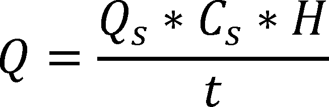
5. 4. Fuel Input Rate Calculation. To calculate the fuel input rate, use the following equation:

Where,
Q = Fuel input rate, expressed in Btu/h
Qs = Total fuel flow as metered, expressed in ft3 for gas-fired equipment and lb for oil-fired equipment
Cs = Correction applied to the heating value of a gas H, when it is metered at temperature and/or pressure conditions other than the standard conditions for which the value of H is based. Cs=1 for oil-fired equipment.
H = Higher heating value of fuel, expressed in Btu/ft3 for gas-fired equipment and Btu/lb for oil-fired equipment.
t = Duration of measurement of fuel consumption
5. 5. Thermal Efficiency Calculation. Thermal efficiency must be calculated using data from the 30-minute thermal efficiency test. Calculate thermal efficiency, Et, using the following equation:
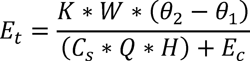
Where,
K = 1.004 Btu/lb· °F, the nominal specific heat of water at 105 °F
W = Total weight of water heated, expressed in lb
θ1 = Average supply water temperature, expressed in °F
θ2 = Average outlet water temperature, expressed in °F
Q = Total fuel flow as metered, expressed in ft3 for gas-fired equipment and lb for oil-fired equipment.
Cs = Correction applied to the heating value of a gas H, when it is metered at temperature and/or pressure conditions other than the standard conditions for which the value of H is based. Cs=1 for oil-fired equipment
H. = Higher heating value of the fuel, expressed in Btu/ft3 for gas-fired equipment and Btu/lb for oil-fired equipment.
Ec = Electrical consumption of the water heater and, when used, the test set-up recirculating pump, expressed in Btu
6. Standby Loss Test
6.1. If no settings on the water heater have changed and the water heater has not been turned off since a previously run thermal efficiency or standby loss test, skip to section 6.3 of this appendix. Otherwise, conduct the soak-in period according to section 6.2 of this appendix.
6.2. Soak-In Period. Conduct a soak-in period, in which the water heater must sit without any draws taking place for at least 12 hours. Begin the soak-in period after setting the tank thermostat as specified in section 3.6 of this appendix, and maintain these thermostat settings throughout the soak-in period.
6.3. Begin the standby loss test at the first cut-out following the end of the soak-in period (if applicable); or at a cut-out following the previous thermal efficiency or standby loss test (if applicable). Allow the water heater to remain in standby mode. Do not change any settings on the water heater at any point until measurements for the standby loss test are finished. Begin recording the applicable parameters specified in section 3.8.3 of this appendix.
6. 4. At the second cut-out, record the time and ambient room temperature, and begin measuring the fuel and electricity consumption. Record the initial mean tank temperature and initial ambient room temperature. For the remainder of the test, continue recording the applicable parameters specified in section 3.8.3 of this appendix.
6. 5. Stop the test after the first cut-out that occurs after 24 hours, or at 48 hours, whichever comes first.
6. 6. Immediately after conclusion of the standby loss test, record the total fuel flow and electrical energy consumption, the final ambient room temperature, the duration of the standby loss test, and if the test ends at 48 hours without a cut-out, the final mean tank temperature, or if the test ends after a cut-out, the maximum mean tank temperature that occurs after the cut-out. Calculate the average of the recorded values of the mean tank temperature and of the ambient room temperature taken at each measurement interval, including the initial and final values.
6. 7. Standby Loss Calculation. To calculate the standby loss, follow the steps below:
6. 7.1. The standby loss expressed as a percentage (per hour) of the heat content of the stored water above room temperature must be calculated using the following equation:
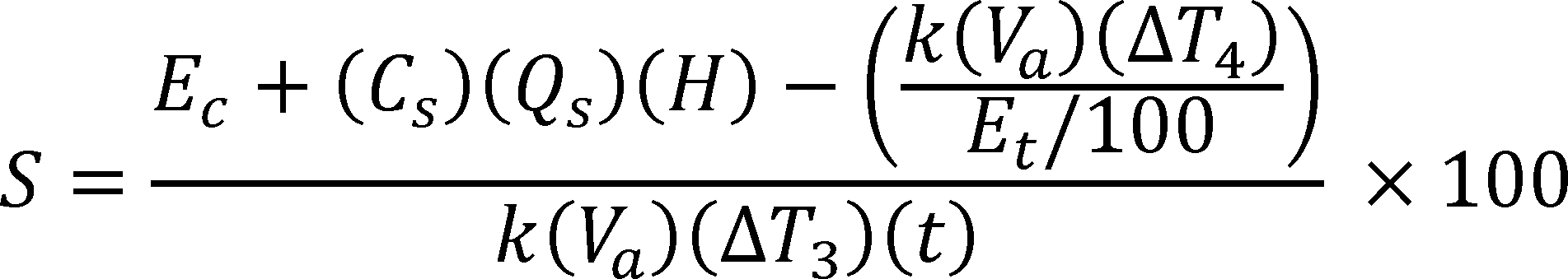
Where,
ΔT3 = Average value of the mean tank temperature minus the average value of the ambient room temperature, expressed in °F
ΔT4 = Final mean tank temperature measured at the end of the test minus the initial mean tank temperature measured at the start of the test , expressed in °F
k = 8.25 Btu/gallon· °F, the nominal specific heat of water
Va = Volume of water contained in the water heater in gallons measured in accordance with section 4 of this appendix
Et = Thermal efficiency of the water heater determined in accordance with this appendix, expressed in %
Ec = Electrical energy consumed by the water heater during the duration of the test in Btu
t = Total duration of the test in hours
Cs = Correction applied to the heating value of a gas H, when it is metered at temperature and/or pressure conditions other than the standard conditions for which the value of H is based. Cs=1 for oil-fired equipment.
Qs = Total fuel flow as metered, expressed in ft3 (gas) or lb (oil)
H = Higher heating value of fuel, expressed in Btu/ft3 (gas) or Btu/lb (oil)
S = Standby loss, the average hourly energy required to maintain the stored water temperature expressed as a percentage of the heat content of the stored water above room temperature
6.7.2. The standby loss expressed in Btu per hour must be calculated as follows:
SL (Btu per hour) = S (% per hour) × 8.25 (Btu/gal- °F) × Measured Volume (gal) × 70 ( °F).
Where, SL refers to the standby loss of the water heater, defined as the amount of energy required to maintain the stored water temperature expressed in Btu per hour
[81 FR 79323, Nov. 10, 2016]
Appendix B to Subpart G of Part 431—Uniform Test Method for the Measurement of Standby Loss of Electric Storage Water Heaters and Storage-Type Instantaneous Water Heaters
Note: Prior to November 6, 2017, manufacturers must make any representations with respect to the energy use or efficiency of the subject commercial water heating equipment in accordance with the results of testing pursuant to this appendix or the procedures in 10 CFR 431.106 that were in place on January 1, 2016. On and after November 6, 2017, manufacturers must make any representations with respect to energy use or efficiency of electric storage water heaters and storage-type instantaneous water heaters in accordance with the results of testing pursuant to this appendix to demonstrate compliance with the energy conservation standards at 10 CFR 431.110.
1. General
Determine the standby loss in accordance with the following sections of this appendix. Certain sections reference sections of Annex E.1 of ANSI Z21.10.3-2015 (incorporated by reference; see § 431.105). Where the instructions contained in the sections below conflict with instructions in Annex E.1 of ANSI Z21.10.3-2015, the instructions contained in this appendix control.
2. Test Set-Up
2.1. Placement of Water Heater. A water heater for installation on combustible floors must be placed on a 3⁄4-inch plywood platform supported by three 2 × 4-inch runners. If the water heater is for installation on noncombustible floors, suitable noncombustible material must be placed on the platform. When the use of the platform for a large water heater is not practical, the water heater may be placed on any suitable flooring. A wall-mounted water heater must be mounted on a simulated wall section.
2.2. Installation of Temperature Sensors. Inlet and outlet piping must be turned vertically downward from the connections on a tank-type water heater so as to form heat traps. Temperature sensors for measuring supply water temperature must be installed upstream of the inlet heat trap piping, in accordance with Figure 2.1, 2.2, or 2.3 (as applicable) of this appendix.
The water heater must meet the requirements shown in either Figure 2.1, 2.2, or 2.3 (as applicable) at all times during the conduct of the standby loss test. Any factory-supplied heat traps must be installed per the installation instructions while ensuring the requirements in Figure 2.1, 2.2, or 2.3 are met. All dimensions specified in Figure 2.1, 2.2, and 2.3 are measured from the outer surface of the pipes and water heater outer casing (as applicable).


2.3. Installation of Temperature Sensors for Measurement of Mean Tank Temperature. Install temperature sensors inside the tank for measurement of mean tank temperature according to the instructions in paragraph f of Annex E.1 of ANSI Z21.10.3-2015 (incorporated by reference; see § 431.105 rt). Calculate the mean tank temperature as the average of the six installed temperature sensors.
2.4. Piping Insulation. Insulate all water piping external to the water heater jacket, including heat traps and piping that is installed by the manufacturer or shipped with the unit, for at least 4 ft of piping length from the connection at the appliance, with material having an R-value not less than 4 °F·ft2·h/Btu. Ensure that the insulation does not contact any appliance surface except at the location where the pipe connections penetrate the appliance jacket or enclosure.
2.5. Temperature and Pressure Relief Valve Insulation. If the manufacturer or has not provided a temperature and pressure relief valve, one shall be installed and insulated as specified in section 2.4 of this appendix.
2.6. Energy Consumption. Install equipment that determines, within ± 1 percent, the quantity of electricity consumed by factory-supplied water heater components.
3. Test Conditions
3.1. Water Supply
3.1.1. Water Supply Pressure. The pressure of the water supply must be maintained between 40 psi and the maximum pressure specified by the manufacturer of the unit being tested. The accuracy of the pressure-measuring devices must be within ± 1.0 pounds per square inch (psi).
3.1.2. Water Supply Temperature. When filling the tank with water prior to the soak-in period, maintain the supply water temperature at 70 °F ± 2 °F.
3.1.3. Isolate the water heater using a shutoff valve in the supply line with an expansion tank installed in the supply line downstream of the shutoff valve. There must be no shutoff means between the expansion tank and the appliance inlet.
3.2. Electrical Supply. Maintain the electrical supply voltage to within ± 5 percent of the voltage specified on the water heater nameplate. If a voltage range is specified on the nameplate, maintain the voltage to within ± 5 percent of the center of the voltage range specified on the nameplate.
3.3. Ambient Room Temperature. During the soak-in period and the standby loss test, maintain the ambient room temperature at 75 °F ± 10 °F at all times. Measure the ambient room temperature at 1-minute intervals during these periods, except for the soak-in period. Measure the ambient room temperature once before beginning the soak-in period, and ensure no actions are taken during the soak-in period that would cause the ambient room temperature to deviate from the allowable range. Measure the ambient room temperature at the vertical mid-point of the water heater and approximately 2 feet from the water heater jacket. Shield the sensor against radiation. Calculate the average ambient room temperature for the standby loss test. During the standby loss test, the ambient room temperature must not vary by more than ± 5.0 °F at any reading from the average ambient room temperature.
3.4. Maximum Air Draft. During the standby loss test, the water heater must be located in an area protected from drafts of more than 50 ft/min. Prior to beginning the standby loss test, measure the air draft within three feet of the jacket of the water heater to ensure this condition is met. Ensure that no other changes that would increase the air draft are made to the test set-up or conditions during the conduct of the test.
3.5. Setting the Tank Thermostat(s). Before starting the required soak-in period, the thermostat setting(s) must first be obtained as explained in the following sections. The thermostat setting(s) must be obtained by starting with the tank full of water at 70 °F ± 2 °F. After the tank is completely filled with water at 70 °F ± 2 °F, turn off the water flow, and set the thermostat(s) as follows.
3.5.1. For water heaters with a single thermostat, the thermostat setting must be set so that the maximum mean tank temperature after cut-out is 140 °F ± 5 °F.
3.5.2. For water heaters with multiple adjustable thermostats, set only the topmost and bottommost thermostats, and turn off any other thermostats for the duration of the standby loss test. Set the topmost thermostat first to yield a maximum mean water temperature after cut-out of 140 °F ± 5 °F, as calculated using only the temperature readings measured at locations in the tank higher than the heating element corresponding to the topmost thermostat (the lowermost heating element corresponding to the topmost thermostat if the thermostat controls more than one element). While setting the topmost thermostat, all lower thermostats must be turned off so that no elements below that (those) corresponding to the topmost thermostat are in operation. After setting the topmost thermostat, set the bottommost thermostat to yield a maximum mean water temperature after cut-out of 140 °F ± 5 °F. When setting the bottommost thermostat, calculate the mean tank temperature using all the temperature sensors installed in the tank as per section 2.3 of this appendix.
3.6. Data Collection Intervals. Follow the data recording intervals specified in the following sections.
3.6.1. Soak-In Period. Measure the ambient room temperature, in °F, every minute during the soak-in period.
3.6.2. Standby Loss Test. Follow the data recording intervals specified in Table 3.1 of this appendix. Additionally, the electricity consumption over the course of the entire test must be measured and used in calculation of standby loss.
Table 3.1—Data To Be Recorded Before and During the Standby Loss Test
| Item recorded | Before test | Every 1
minutea |
|---|---|---|
| Air draft, ft/min | X | |
| Time, minutes/seconds | X | |
| Mean tank temperature, °F | Xb | |
| Ambient room temperature, °F | X |
4. Determination of Storage Volume. Determine the storage volume by subtracting the tare weight, measured while the system is dry and empty, from the weight of the system when filled with water and dividing the resulting net weight of water by the density of water at the measured water temperature. The volume of water contained in the water heater must be computed in gallons.
5. Standby Loss Test
5.1. If no settings on the water heater have changed and the water heater has not been turned off since a previously run standby loss test, skip to section 5.3 of this appendix. Otherwise, conduct the soak-in period according to section 5.2 of this appendix.
5.2. Soak-In Period. Conduct a soak-in period, in which the water heater must sit without any draws taking place for at least 12 hours. Begin the soak-in period after setting the tank thermostat(s) as specified in section 3.5 of this appendix, and maintain these settings throughout the soak-in period.
5.3. Begin the standby loss test at the first cut-out following the end of the soak-in period (if applicable), or at a cut-out following the previous standby loss test (if applicable). Allow the water heater to remain in standby mode. At this point, do not change any settings on the water heater until measurements for the standby loss test are finished. Begin recording applicable parameters as specified in section 3.6.2 of this appendix.
5.4. At the second cut-out, record the time and ambient room temperature, and begin measuring the electric consumption. Record the initial mean tank temperature and initial ambient room temperature. For the remainder of the test, continue recording the applicable parameters specified in section 3.6.2 of this appendix.
5.5. Stop the test after the first cut-out that occurs after 24 hours, or at 48 hours, whichever comes first.
5.6. Immediately after conclusion of the standby loss test, record the total electrical energy consumption, the final ambient room temperature, the duration of the standby loss test, and if the test ends at 48 hours without a cut-out, the final mean tank temperature, or if the test ends after a cut-out, the maximum mean tank temperature that occurs after the cut-out. Calculate the average of the recorded values of the mean tank temperature and of the ambient air temperatures taken at each measurement interval, including the initial and final values.
5.7. Standby Loss Calculation. To calculate the standby loss, follow the steps below:
5.7.1 The standby loss expressed as a percentage (per hour) of the heat content of the stored water above room temperature must be calculated using the following equation:

Where,
ΔT3 = Average value of the mean tank temperature minus the average value of the ambient room temperature, expressed in °F
ΔT4 = Final mean tank temperature measured at the end of the test minus the initial mean tank temperature measured at the start of the test, expressed in °F
k = 8.25 Btu/gallon· °F, the nominal specific heat of water
Va = Volume of water contained in the water heater in gallons measured in accordance with section 4 of this appendix
Et = Thermal efficiency = 98 percent for electric water heaters with immersed heating elements
Ec = Electrical energy consumed by the water heater during the duration of the test in Btu
t = Total duration of the test in hours
S = Standby loss, the average hourly energy required to maintain the stored water temperature expressed as a percentage of the heat content of the stored water above room temperature
[81 FR 79328, Nov. 10, 2016]
Appendix C to Subpart G of Part 431—Uniform Test Method for the Measurement of Thermal Efficiency and Standby Loss of Gas-Fired and Oil-Fired Instantaneous Water Heaters and Hot Water Supply Boilers (Other Than Storage-Type Instantaneous Water Heaters)
Prior to November 6, 2017, manufacturers must make any representations with respect to the energy use or efficiency of the subject commercial water heating equipment in accordance with the results of testing pursuant to this appendix or the procedures in 10 CFR 431.106 that were in place on January 1, 2016. On and after November 6, 2017, manufacturers must make any representations with respect to energy use or efficiency of gas-fired and oil-fired instantaneous water heaters and hot water supply boilers (other than storage-type instantaneous water heaters) in accordance with the results of testing pursuant to this appendix to demonstrate compliance with the energy conservation standards at 10 CFR 431.110.
1. General
Determine the thermal efficiency and standby loss (as applicable) in accordance with the following sections of this appendix. Certain sections reference sections of Annex E.1 of ANSI Z21.10.3-2015 (incorporated by reference; see § 431.105). Where the instructions contained in the sections below conflict with instructions in Annex E.1 of ANSI Z21.10.3-2015, the instructions contained in this appendix control.
2. Test Set-Up
2.
1. Placement of Water Heater. A water heater for installation on combustible floors must be placed on a 3⁄4-inch plywood platform supported by three 2 x 4-inch runners. If the water heater is for installation on noncombustible floors, suitable noncombustible material must be placed on the platform. When the use of the platform for a large water heater is not practical, the water heater may be placed on any suitable flooring. A wall-mounted water heater must be mounted on a simulated wall section.
2.
2. Test Configuration. If the instantaneous water heater or hot water supply boiler is not required to be tested using a recirculating loop, then set up the unit in accordance with Figures 2.1, 2.2, or 2.3 of this appendix (as applicable). If the unit is required to be tested using a recirculating loop, then set up the unit as per Figure 2.4 of this appendix.


2.2.1. If the instantaneous water heater or hot water supply boiler does not have any external piping, install an outlet water valve within 10 inches of piping length of the water heater jacket or enclosure. If the instantaneous water heater or hot water supply boiler includes external piping assembled at the manufacturer's premises prior to shipment, install water valves in the outlet piping within 5 inches of the end of the piping supplied with the unit.
2. 2.2. If the water heater is not able to achieve an outlet water temperature of 70 °F ± 2 °F (TOWT) above the supply water temperature at full firing rate, a recirculating loop with pump as shown in Figure 2.4 of this appendix must be used.
2.2.2.1. If a recirculating loop with a pump is used, then ensure that the inlet water temperature labeled as TIWT in Figure 2.4 of this appendix, is greater than or equal to 70 °F and less than or equal to 120 °F at all times during the thermal efficiency test and steady-state verification period (as applicable).
2.3. Installation of Temperature Sensors
2.3.1. Without Recirculating Loop.
2.3.1.1. Vertical Connections. Use Figure 2.1 (for top connections) and 2.2 (for bottom connections) of this appendix.
2.3.1.2. Horizontal Connections. Use Figure 2.3 of this appendix.
2.3.2. With Recirculating Loop. Set up the recirculating loop as shown in Figure 2.4 of this appendix.
2.3.3. For water heaters with multiple outlet water connections leaving the water heater jacket that are required to be operated to achieve the rated input, temperature sensors must be installed for each outlet water connection leaving the water heater jacket or enclosure that is used during testing, in accordance with the provisions in sections 2.3.1 and 2.3.2 of this appendix (as applicable).
2. 4. Piping Insulation. Insulate all water piping external to the water heater jacket or enclosure, including piping that is installed by the manufacturer or shipped with the unit, for at least 4 ft of piping length from the connection at the appliance with material having an R-value not less than 4 °F·ft2·h/Btu. Ensure that the insulation does not contact any appliance surface except at the location where the pipe connections penetrate the appliance jacket or enclosure.
2.5. Temperature and Pressure Relief Valve Insulation. If the manufacturer has not provided a temperature and pressure relief valve, one shall be installed and insulated as specified in section 2.4 of this appendix. The temperature and pressure relief valve must be installed in the outlet water piping, between the unit being tested and the outlet water valve.
2. 6. Vent Requirements. Follow the requirements for venting arrangements specified in paragraph c of Annex E.1 of ANSI Z21.10.3-2015 (incorporated by reference; see § 431.105).
2. 7. Energy Consumption. Install equipment that determines, within ± 1 percent:
2. 7.1. The quantity and rate of fuel consumed.
2.7.2. The quantity of electricity consumed by factory-supplied water heater components, and of the test loop recirculating pump, if used.
3. Test Conditions
3.1. Water Supply
3.1.1. Water Supply Pressure. The pressure of the water supply must be maintained between 40 psi and the maximum pressure specified by the manufacturer of the unit being tested. The accuracy of the pressure-measuring devices must be within ± 1.0 psi.
3. 1.2. Water Supply Temperature. During the thermal efficiency test and steady-state verification period (as applicable), the temperature of the supply water (TSWT) must be maintained at 70 °F ± 2 °F.
3.
2. Gas Pressure for Gas-Fired Equipment. The supply gas pressure must be within the range specified by the manufacturer on the nameplate of the unit being tested. The difference between the outlet pressure of the gas appliance pressure regulator and the value specified by the manufacturer on the nameplate of the unit being tested must not exceed the greater of: ± 10 percent of the nameplate value or ± 0.2 inches water column (in. w.c.). Obtain the higher heating value of the gas burned.
3.3. Ambient Room Temperature. Maintain the ambient room temperature at 75 °F ± 10 °F at all times during the steady-state verification period, the thermal efficiency test, and the standby loss test (as applicable). Measure the ambient room temperature at 1-minute intervals during these periods. Measure the ambient room temperature at the vertical mid-point of the water heater and approximately 2 feet from the water heater jacket or enclosure. Shield the sensor against radiation. Calculate the average ambient room temperature separately for the thermal efficiency test and the standby loss test. During the thermal efficiency and standby loss tests, the ambient room temperature must not vary by more than ± 5.0 °F at any reading from the average ambient room temperature.
3.4. Test Air Temperature. During the steady-state verification period, the thermal efficiency test, and the standby loss test (as applicable), the test air temperature must not vary by more than ± 5 °F from the ambient room temperature at any reading. Measure the test air temperature at 1-minute intervals during these periods and at a location within two feet of the air inlet of the water heater or the combustion air intake vent, as applicable. Shield the sensor against radiation. For units with multiple air inlets, measure the test air temperature at each air inlet, and maintain the specified tolerance on deviation from the ambient room temperature at each air inlet. For units without a dedicated air inlet, measure the test air temperature within two feet of any location on the water heater where combustion air is drawn.
3. 5. Maximum Air Draft. During the steady-state verification period, the thermal efficiency test, and the standby loss test (as applicable), the water heater must be located in an area protected from drafts of more than 50 ft/min. Prior to beginning the steady-state verification period and the standby loss test, measure the air draft within three feet of the jacket or enclosure of the water heater to ensure this condition is met. Ensure that no other changes that would increase the air draft are made to the test set-up or conditions during the conduct of the tests.
3.6. Primary Control
3.6.1. Thermostatically-Activated Water Heaters With an Internal Thermostat. Before starting the thermal efficiency test and the standby loss test (unless the thermostat is already set before the thermal efficiency test), the thermostat setting must be obtained. Set the thermostat to ensure:
3.6.1.1. With supply water temperature set as per section 3.1.2 of this appendix (i.e., 70 °F ± 2 °F) the water flow rate can be varied so that the outlet water temperature is constant at 70 °F ± 2 °F above the supply water temperature, while the burner is firing at full firing rate; and
3.6.1.2. After the water supply is turned off and the thermostat reduces the fuel supply to a minimum, the maximum heat exchanger outlet water temperature (TOHX) is 140 °F ± 5 °F.
3.6.1.3. If the water heater includes a built-in safety mechanism that prevents it from achieving a heat exchanger outlet water temperature of 140 °F ± 5 °F, adjust the thermostat to its maximum setting.
3.6.2. Flow-Activated Instantaneous Water Heaters and Thermostatically-Activated Instantaneous Water Heaters With an External Thermostat. Energize the primary control such that it is always calling for heating and the burner is firing at the full firing rate. Maintain the supply water temperature as per section 3.1.2 of this appendix (i.e., 70 °F ± 2 °F). Set the control so that the outlet water temperature (TOWT) is 140 °F ± 5 °F. If the water heater includes a built-in safety mechanism that prevents it from achieving a heat exchanger outlet water temperature of 140 °F ± 5 °F, adjust the control to its maximum setting.
3.7. Units With Multiple Outlet Water Connections
3.7.1. For each connection leaving the water heater that is required for the unit to achieve the rated input, the outlet water temperature must not differ from that of any other outlet water connection by more than 2 °F during the steady-state verification period and thermal efficiency test.
3.7.2. Determine the outlet water temperature representative for the entire unit at every required measurement interval by calculating the average of the outlet water temperatures measured at each connection leaving the water heater jacket or enclosure that is used during testing. Use the outlet water temperature representative for the entire unit in all calculations for the thermal efficiency and standby loss tests, as applicable.
3.8. Additional Requirements for Oil-Fired Equipment.
3. 8.1. Venting Requirements. Connect a vertical length of flue pipe to the flue gas outlet of sufficient height so as to meet the minimum draft specified by the manufacturer.
3.8.2. Oil Supply. Adjust the burner rate so that the following conditions are met:
3.8.2.1. The CO2 reading is within the range specified by the manufacturer;
3.8.2.2. The fuel pump pressure is within ± 10 percent of manufacturer's specifications;
3.8.2.3. If either the fuel pump pressure or range for CO2 reading are not specified by the manufacturer on the nameplate of the unit, in literature shipped with the unit, or in supplemental test report instructions included with a certification report, then a default value of 100 psig is to be used for fuel pump pressure, and a default range of 9-12 percent is to be used for CO2 reading; and
3.8.2.4. Smoke in the flue does not exceed No. 1 smoke as measured by the procedure in ASTM D2156-09 (Reapproved 2013) (incorporated by reference, see § 431.105). To determine the smoke spot number, the smoke measuring device shall be connected to an open-ended tube. This tube must project into the flue 1⁄4 to 1⁄2 of the pipe diameter.
3.8.2.5. If no settings on the water heater have been changed and the water heater has not been turned off since the end of a previously run thermal efficiency (or standby loss test for thermostatically-activated instantaneous water heaters with an internal thermostat), measurement of the CO2 reading and conduct of the smoke spot test are not required prior to beginning a test. Otherwise, measure the CO2 reading and determine the smoke spot number, with the burner firing, before beginning measurements for the steady-state verification period (prior to beginning the thermal efficiency test or standby loss test, as applicable). However, measurement of the CO2 reading and conduct of the smoke spot test are not required for the standby loss test for thermostatically-activated instantaneous water heaters with an external thermostat and flow-activated instantaneous water heaters.
3. 9. Data Collection Intervals. Follow the data recording intervals specified in the following sections.
3. 9.1. Steady-State Verification Period and Thermal Efficiency Test. For the steady-state verification period and the thermal efficiency test, follow the data recording intervals specified in Table 3.1 of this appendix. These data recording intervals must also be followed if conducting a steady-state verification period prior to conducting the standby loss test.
Table 3.1—Data To Be Recorded Before and During the Steady-State Verification Period and Thermal Efficiency Test
| Item recorded | Before
steady-state verification period |
Every 1
minutea |
Every 10
minutes |
|---|---|---|---|
| Gas supply pressure, in w.c. | X | ||
| Gas outlet pressure, in w.c. | X | ||
| Barometric pressure, in Hg | X | ||
| Fuel higher heating value, Btu/ft3 (gas) or Btu/lb (oil) | X | ||
| Oil pump pressure, psig (oil only) | X | ||
| CO2 reading, % (oil only) | Xb | ||
| Oil smoke spot reading (oil only) | Xb | ||
| Air draft, ft/min | X | ||
| Time, minutes/seconds | X | ||
| Fuel weight or volume, lb (oil) or ft3 (gas) | Xc | ||
| Supply water temperature (TSWT), °F | X | ||
| Inlet water temperature (TIWT), °F | Xd | ||
| Outlet water temperature (TOWT), °F | X | ||
| Ambient room temperature, °F | X | ||
| Test air temperature, °F | X | ||
| Water flow rate, gpm | X |
3.9.2. Standby Loss Test. For the standby loss test, follow the data recording intervals specified in Table 3.2 of this appendix. (Follow the data recording intervals specified in Table 3.1 of this appendix of the steady-state verification period, if conducted prior to the standby loss test.) Additionally, the fuel and electricity consumption over the course of the entire test must be measured and used in calculation of standby loss.
Table 3.2—Data To Be Recorded Before and During the Standby Loss Test
| Item recorded | Before test | Every 1
minutea |
|
|---|---|---|---|
| Gas supply pressure, in w.c. | X | ||
| Gas outlet pressure, in w.c. | X | ||
| Barometric pressure, in Hg | X | ||
| Fuel higher heating value, Btu/ft3 (gas) or Btu/lb (oil) | X | ||
| Oil pump pressure, psig (oil only) | X | ||
| Air draft, ft/min | X | ||
| Time, minutes/seconds | X | ||
| Heat exchanger outlet water temperature (TOHX), °F | X | ||
| Ambient room temperature, °F | X | ||
| Test air temperature, °F | X | ||
| Water flow rate, gpm | Xb | ||
| Inlet water temperature (TIWT), °F | Xb |
4. Determination of Storage Volume. Determine the storage volume by subtracting the tare weight, measured while the system is dry and empty, from the weight of the system when filled with water and dividing the resulting net weight of water by the density of water at the measured water temperature. The volume of water contained in the water heater must be computed in gallons.
5. Fuel Input Rate
5.1. Determination of Fuel Input Rate. During the steady-state verification period and thermal efficiency test, as applicable, record the fuel consumption at 10-minute intervals. Calculate the fuel input rate for each 10-minute period using the equations in section 5.2 of this appendix. The measured fuel input rates for these 10-minute periods must not vary by more than ± 2 percent between any two readings. Determine the overall fuel input rate using the fuel consumption for the entire duration of the thermal efficiency test.
5.2. Fuel Input Rate Calculation. To calculate the fuel input rate, use the following equation:
Where:
Q = Fuel input rate, expressed in Btu/h
Qs = Total fuel flow as metered, expressed in ft3 for gas-fired equipment and lb for oil-fired equipment
Cs = Correction applied to the heating value of a gas H, when it is metered at temperature and/or pressure conditions other than the standard conditions for which the value of H is based. Cs=1 for oil-fired equipment.
H = Higher heating value of the fuel, expressed as Btu/ft3 for gas-fired equipment and Btu/lb for oil-fired equipment.
t = Duration of measurement of fuel consumption
6. Thermal Efficiency Test. Before beginning the steady-state verification period, record the applicable parameters as specified in section 3.9.1 of this appendix. Begin drawing water from the unit by opening the main supply and outlet water valve, and adjust the water flow rate to achieve an outlet water temperature of 70 °F ± 2 °F above supply water temperature. The thermal efficiency test shall be deemed complete when there is a continuous, one-hour-long period where the steady-state conditions specified in section 6.1 of this appendix have been met, as confirmed by consecutive readings of the relevant parameters at 1-minute intervals (except for fuel input rate, which is determined at 10-minute intervals, as specified in section 5.1 of this appendix). During the one-hour-long period, the water heater must fire continuously at its full firing rate (i.e., no modulation or cut-outs) and no settings can be changed on the unit being tested at any time. The first 30 minutes of the one-hour-period where the steady-state conditions in section 6.1 of this appendix are met is the steady-state verification period. The final 30 minutes of the one-hour-period where the steady-state conditions in section 6.1 of this appendix are met is the thermal efficiency test. The last reading of the steady-state verification period must be the first reading of the thermal efficiency test (i.e., the thermal efficiency test starts immediately once the steady-state verification period ends).
6.1. Steady-State Conditions. The following conditions must be met at consecutive readings taken at 1-minute intervals (except for fuel input rate, for which measurements are taken at 10-minute intervals) to verify the water heater has achieved steady-state operation during the steady-state verification period and the thermal efficiency test.
6.1.1. The water flow rate must be maintained within ± 0.25 gallons per minute (gpm) of the initial reading at the start of the steady-state verification period.
6.1.2. Outlet water temperature must be maintained at 70 °F ± 2 °F above supply water temperature.
6.1.3. Fuel input rate must be maintained within ± 2 percent of the rated input certified by the manufacturer.
6.1.4. The supply water temperature (TSWT) (or inlet water temperature (TIWT) if a recirculating loop is used) must be maintained within ± 0.50 °F of the initial reading at the start of the steady-state verification period.
6.1.5. The rise between supply (or inlet if a recirculating loop is used) and outlet water temperatures must be maintained within ± 0.50 °F of its initial value taken at the start of the steady-state verification period for units with rated input less than 500,000 Btu/h, and maintained within ± 1.00 °F of its initial value for units with rated input greater than or equal to 500,000 Btu/h.
6.2. Water Flow Measurement. Measure the total weight of water heated during the 30-minute thermal efficiency test with either a scale or a water flow meter. With either method, the error of measurement of weight of water heated must not exceed 1 percent of the weight of the total draw.
6.3. Thermal Efficiency Calculation. Thermal efficiency must be calculated using data from the 30-minute thermal efficiency test. Calculate thermal efficiency, Et, using the following equation:

Where:
K = 1.004 Btu/lb· °F, the nominal specific heat of water at 105 °F
W = Total weight of water heated, lb
θ1 = Average supply water temperature, expressed in °F
θ2 = Average outlet water temperature, expressed in °F
Q = Total fuel flow as metered, expressed in ft3 (gas) or lb (oil)
Cs = Correction applied to the heating value of a gas H, when it is metered at temperature and/or pressure conditions other than the standard conditions for which the value of H is based. Cs=1 for oil-fired equipment.
H = Higher heating value of the fuel, expressed in Btu/ft3 (gas) or Btu/lb (oil)
Ec = Electrical consumption of the water heater and, when used, the test set-up recirculating pump, expressed in Btu
7. Standby Loss Test. If the standby loss test is conducted immediately after a thermal efficiency test and no settings or conditions have been changed since the completion of the thermal efficiency test, then skip to section 7.2 or 7.3 of this appendix (as applicable). Otherwise, perform the steady-state verification in section 7.1 of this appendix. For thermostatically-activated instantaneous water heaters with an internal thermostat, use section 7.2 of this appendix to conduct the standby loss test, and for flow-activated and/or thermostatically-activated instantaneous water heaters with an external thermostat use section 7.3 of this appendix to conduct the standby loss test.
7.1. Steady-State Verification Period. For water heaters where the standby loss test is not conducted immediately following the thermal efficiency test, the steady-state verification period must be conducted before starting the standby loss test. Set the primary control in accordance with section 3.6 of this appendix, such that the primary control is always calling for heat and the water heater is firing continuously at the full firing rate (i.e., no modulation or cut-outs). Begin drawing water from the unit by opening the main supply and the outlet water valve, and adjust the water flow rate to achieve an outlet water temperature of 70 °F ± 2 °F above supply water temperature. The steady-state verification period is complete when there is a continuous 30-minute period where the steady-state conditions specified in section 7.1.1 of this appendix are met, as confirmed by consecutive readings of the relevant parameters recorded at 1-minute intervals (except for fuel input rate, which is determined at 10-minute intervals, as specified in section 5.1 of this appendix).
7.1.1. Steady-State Conditions. The following conditions must be met at consecutive readings taken at 1-minute intervals (except for fuel input rate, for which measurements are taken at 10-minute intervals) to verify the water heater has achieved steady-state operation during the steady-state verification period prior to conducting the standby loss test.
7.1.1.1. The water flow rate must be maintained within ± 0.25 gallons per minute (gpm) of the initial reading at the start of the steady-state verification period;
7.1.1.2. Fuel input rate must be maintained within ± 2 percent of the rated input certified by the manufacturer;
7.1.1.3. The supply water temperature (TSWT) (or inlet water temperature (TIWT) if a recirculating loop is used) must be maintained within ± 0.50 °F of the initial reading at the start of the steady-state verification period; and
7.1.1.4. The rise between the supply (or inlet if a recirculating loop is used) and outlet water temperatures must be maintained within ± 0.50 °F of its initial value taken at the start of the steady-state verification period for units with rated input less than 500,000 Btu/h, and maintained within ± 1.00 °F of its initial value for units with rated input greater than or equal to 500,000 Btu/h.
7.2. Thermostatically-Activated Instantaneous Water Heaters with an Internal Thermostat. For water heaters that will experience cut-in based on a temperature-activated control that is internal to the water heater, use the following steps to conduct the standby loss test.
7.2.1. Immediately after the thermal efficiency test or the steady-state verification period (as applicable), turn off the outlet water valve(s) (installed as per the provisions in section 2.2 of this appendix), and the water pump (if applicable) simultaneously and ensure that there is no flow of water through the water heater.
7. 2.2. After the first cut-out following the end of the thermal efficiency test or steady-state verification period (as applicable), allow the water heater to remain in standby mode. Do not change any settings on the water heater at any point until measurements for the standby loss test are finished. Begin recording the applicable parameters specified in section 3.9.2 of this appendix.
7. 2.3. At the second cut-out, record the time and ambient room temperature, and begin measuring the fuel and electricity consumption. Record the initial heat exchanger outlet water temperature (TOHX) and initial ambient room temperature. For the remainder of the test, continue recording the applicable parameters specified in section 3.9.2 of this appendix.
7. 2.4. Stop the test after the first cut-out that occurs after 24 hours, or at 48 hours, whichever comes first.
7. 2.5. Immediately after conclusion of the standby loss test, record the total fuel flow and electrical energy consumption, the final ambient room temperature, the duration of the standby loss test, and if the test ends at 48 hours without a cut-out, the final heat exchanger outlet temperature, or if the test ends after a cut-out, the maximum heat exchanger outlet temperature that occurs after the cut-out. Calculate the average of the recorded values of the heat exchanger outlet water temperature and the ambient room temperature taken at each measurement interval, including the initial and final values.
7. 2.6. Standby Loss Calculation. To calculate the standby loss, follow the steps below:
7. 2.6.1. The standby loss expressed as a percentage (per hour) of the heat content of the stored water above room temperature must be calculated using the following equation:
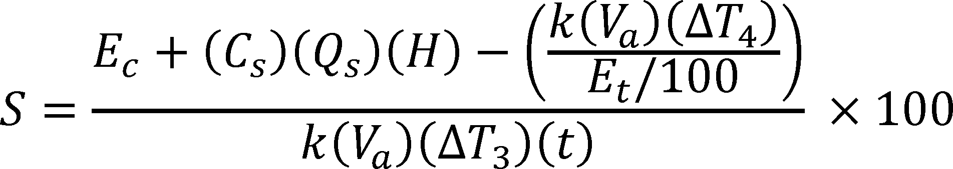
Where:
ΔT3 = Average value of the heat exchanger outlet water temperature (TOHX) minus the average value of the ambient room temperature, expressed in °F
ΔT4 = Final heat exchanger outlet water temperature (TOHX) measured at the end of the test minus the initial heat exchanger outlet water temperature (TOHX) measured at the start of the test, expressed in °F
K = 8.25 Btu/gallon· °F, the nominal specific heat of water
Va = Volume of water contained in the water heater in gallons measured in accordance with section 4 of this appendix
Et = Thermal efficiency of the water heater determined in accordance with section 6 of this appendix, expressed in %
Ec = Electrical energy consumed by the water heater during the duration of the test in Btu
T = Total duration of the test in hours
Cs = Correction applied to the heating value of a gas H, when it is metered at temperature and/or pressure conditions other than the standard conditions for which the value of H is based. Cs=1 for oil-fired equipment.
Qs = Total fuel flow as metered, expressed in ft3 (gas) or lb (oil)
H = Higher heating value of gas or oil, expressed in Btu/ft3 (gas) or Btu/lb (oil)
S = Standby loss, the average hourly energy required to maintain the stored water temperature expressed as a percentage of the initial heat content of the stored water above room temperature
7.2.6.2. The standby loss expressed in Btu per hour must be calculated as follows:
SL (Btu per hour) = S (% per hour) × 8.25 (Btu/gal- °F) × Measured Volume (gal) × 70 ( °F).
Where, SL refers to the standby loss of the water heater, defined as the amount of energy required to maintain the stored water temperature expressed in Btu per hour.
7.3. Flow-Activated and Thermostatically-Activated Instantaneous Water Heaters with an External Thermostat. For water heaters that are either flow-activated or thermostatically-activated with an external thermostat, use the following steps to conduct the standby loss test.
7.3.1. Immediately after the thermal efficiency test or the steady-state verification period (as applicable), de-energize the primary control to end the call for heating. If the main burners do not cut out, then turn off the fuel supply.
7. 3.1.1. If the unit does not have an integral pump purge functionality, then turn off the outlet water valve and water pump at this time.
7.3.1.2. If the unit has an integral pump purge functionality, allow the pump purge operation to continue. After the pump purge operation is complete, immediately turn off the outlet water valve and water pump and continue recording the required parameters for the remainder of the test.
7.3.2. Recording Data
7.3.2.1. For units with pump purge functionality, record the initial heat exchanger outlet water temperature (TOHX), and ambient room temperature when the main burner(s) cut-out or the fuel supply is turned off. After the pump purge operation is complete, record the time as t = 0 and the initial electricity meter reading. Continue to monitor and record the heat exchanger outlet water temperature (TOHX) and time elapsed from the start of the test, and the electricity consumption as per the requirements in section 3.9.2 of this appendix.
7.3.2.2. For units not equipped with pump purge functionality, begin recording the measurements as per the requirements of section 3.9.2 of this appendix when the main burner(s) cut-out or the fuel supply is turned off. Specifically, record the time as t = 0, and record the initial heat exchanger outlet water temperature (TOHX), ambient room temperature, and electricity meter readings. Continue to monitor and record the heat exchanger outlet water temperature (TOHX) and the time elapsed from the start of the test as per the requirements in section 3.9.2 of this appendix.
7.3.3. Stopping Criteria. Stop the test when one of the following occurs:
7.3.3.1. The heat exchanger outlet water temperature (TOHX) decreases by 35 °F from its value recorded immediately after the main burner(s) has cut-out, and the pump purge operation (if applicable) is complete; or
7.3.3.2. 24 hours have elapsed from the start of the test.
7.3.4. At the end of the test, record the final heat exchanger outlet water temperature (TOHX), fuel consumed, electricity consumed from time t=0, and the time elapsed from the start of the test.
7.3.5. Standby Loss Calculation
7.3.5.1. Once the test is complete, use the following equation to calculate the standby loss as a percentage (per hour) of the heat content of the stored water above room temperature:
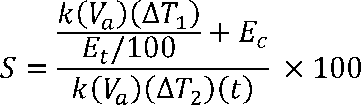
Where,
ΔT1 = Heat exchanger outlet water temperature (TOHX) measured after the pump purge operation is complete (if the unit is integrated with pump purge functionality); or after the main burner(s) cut-out (if the unit is not equipped with pump purge functionality) minus heat exchanger outlet water temperature (TOHX) measured at the end of the test, expressed in °F
ΔT2 = Heat exchanger outlet water temperature (TOHX) minus the ambient temperature, both measured after the main burner(s) cut-out, at the start of the test, expressed in °F
K = 8.25 Btu/gallon· °F, the nominal specific heat of water
Va = Volume of water contained in the water heater in gallons measured in accordance with section 4 of this appendix
Et = Thermal efficiency of the water heater determined in accordance with section 6 of this appendix, expressed in %
Ec = Electrical energy consumed by the water heater during the duration of the test in Btu
t = Total duration of the test in hours
S = Standby loss, the average hourly energy required to maintain the stored water temperature expressed as a percentage of the initial heat content of the stored water above room temperature
7.3.5.2. The standby loss expressed in terms of Btu per hour must be calculated as follows:
SL (Btu per hour) = S (% per hour) × 8.25 (Btu/gal- °F) × Measured Volume (gal) × 70 ( °F)
Where, SL refers to the standby loss of the water heater, defined as the amount of energy required to maintain the stored water temperature expressed in Btu per hour.
[81 FR 79332, Nov. 10, 2016]
Appendix D to Subpart G of Part 431—Uniform Test Method for the Measurement of Standby Loss of Electric Instantaneous Water Heaters (Other Than Storage-Type Instantaneous Water Heaters)
Note: Prior to November 6, 2017, manufacturers must make any representations with respect to the energy use or efficiency of the subject commercial water heating equipment in accordance with the results of testing pursuant to this appendix or the procedures in 10 CFR 431.106 that were in place on January 1, 2016. On and after November 6, 2017, manufacturers must make any representations with respect to energy use or efficiency of electric instantaneous water heaters (other than storage-type instantaneous water heaters) in accordance with the results of testing pursuant to this appendix to demonstrate compliance with the energy conservation standards at 10 CFR 431.110.
1. General
Determine the standby loss (as applicable) in accordance with the following sections of this appendix.
2. Test Set-Up
2.
1. Placement of Water Heater. A water heater for installation on combustible floors must be placed on a 3⁄4-inch plywood platform supported by three 2 × 4-inch runners. If the water heater is for installation on noncombustible floors, suitable noncombustible material must be placed on the platform. When the use of the platform for a large water heater is not practical, the water heater may be placed on any suitable flooring. A wall-mounted water heater must be mounted on a simulated wall section.
2.
2. Test Configuration. If the instantaneous water heater is not required to be tested using a recirculating loop, then set up the unit in accordance with Figure 2.1, 2.2, or 2.3 of this appendix (as applicable). If the unit is required to be tested using a recirculating loop, then set up the unit as per Figure 2.4 of this appendix.


2.2.1. If the instantaneous water heater does not have any external piping, install an outlet water valve within 10 inches of the piping length of the water heater jacket or enclosure. If the instantaneous water heater includes external piping assembled at the manufacturer's premises prior to shipment, install water valves in the outlet piping within 5 inches of the end of the piping supplied with the unit.
2.2.2. If the water heater is not able to achieve an outlet water temperature of 70 °F ± 2 °F above the supply water temperature at a constant maximum electricity input rate, a recirculating loop with pump as shown in Figure 2.4 of this appendix must be used.
2. 2.2.1. If a recirculating loop with a pump is used, then ensure that the inlet water temperature (labeled as TIWT in Figure 2.4 of this appendix) is greater than or equal to 70 °F and less than or equal to 120 °F at all times during the steady-state verification period.
2.3. Installation of Temperature Sensors
2.3.1. Without Recirculating Loop
2.3.1.1. Vertical Connections. Use Figure 2.1 (for top connections) and 2.2 (for bottom connections) of this appendix.
2.3.1.2. Horizontal Connections. Use Figure 2.3 of this appendix.
2.3.2. With Recirculating Loop. Set up the recirculating loop as shown in Figure 2.4 of this appendix.
2.3.3. For water heaters with multiple outlet water connections leaving the water heater jacket that are required to be operated to achieve the rated input, temperature sensors must be installed for each outlet water connection leaving the water heater jacket or enclosure that is used during testing, in accordance with sections 2.3.1 and 2.3.2 of this appendix.
2.4. Piping Insulation. Insulate all the water piping external to the water heater jacket or enclosure, including piping that is installed by the manufacturer or shipped with the unit, for at least 4 ft of piping length from the connection at the appliance with material having an R-value not less than 4 °F·ft2·h/Btu. Ensure that the insulation does not contact any appliance surface except at the location where the pipe connections penetrate the appliance jacket or enclosure.
2.5. Temperature and Pressure Relief Valve Insulation. If the manufacturer has not provided a temperature and pressure relief valve, one shall be installed and insulated as specified in section 2.4 of this appendix. The temperature and pressure relief valve must be installed in the outlet water piping between the unit being tested and the outlet water valve.
2. 6. Energy Consumption. Install equipment that determines, within ± 1 percent, the quantity of electricity consumed by factory-supplied water heater components, and of the test loop recirculating pump, if used.
3. Test Conditions
3.1. Water Supply
3.1.1. Water Supply Pressure. The pressure of the water supply must be maintained between 40 psi and the maximum pressure specified by the manufacturer of the unit being tested. The accuracy of the pressure-measuring devices must be ± 1.0 psi.
3.1.2. Water Supply Temperature. During the steady-state verification period, the temperature of the supply water (TSWT) must be maintained at 70 °F ± 2 °F.
.2. Electrical Supply. Maintain the electrical supply voltage to within ± 5 percent of the voltage specified on the water heater nameplate. If a voltage range is specified on the nameplate, maintain the voltage to within ± 5 percent of the center of the voltage range specified on the nameplate.
3. 3. Ambient Room Temperature. Maintain the ambient room temperature at 75 °F ± 10 °F at all times during the steady-state verification period and the standby loss test. Measure the ambient room temperature at 1-minute intervals during these periods. Measure the ambient room temperature at the vertical mid-point of the water heater and approximately 2 feet from the water heater jacket or enclosure. Shield the sensor against radiation. Calculate the average ambient room temperature for the standby loss test. During the standby loss test, the ambient room temperature must not vary more than ± 5.0 °F at any reading from the average ambient room temperature.
3.4. Maximum Air Draft. During the steady-state verification period and the standby loss test, the water heater must be located in an area protected from drafts of more than 50 ft/min. Prior to beginning steady-state verification before the standby loss test, measure the air draft within three feet of the jacket or enclosure of the water heater to ensure this condition is met. Ensure that no other changes that would increase the air draft are made to the test set-up or conditions during the conduct of the test.
3.5. Primary Control
3.5.1. Thermostatically-Activated Water Heaters with an Internal Thermostat. Before starting the steady-state verification prior to the standby loss test, the thermostat setting must be obtained. Set the thermostat to ensure:
3.5.1.1. With supply water temperature as per section 3.1.2 of this appendix (i.e., 70 °F ± 2 °F) the water flow rate can be varied so that the outlet water temperature is constant at 70 °F ± 2 °F above the supply water temperature, while the heating element is operating at the rated input.
3.5.1.2. After the water supply is turned off and the thermostat reduces the electricity supply to the heating element to a minimum, the maximum heat exchanger outlet water temperature (TOHX) is 140 °F ± 5 °F.
3.5.1.3. If the water heater includes a built-in safety mechanism that prevents it from achieving a heat exchanger outlet water temperature of 140 °F ± 5 °F, adjust the thermostat to its maximum setting.
3.5.2. Flow-Activated Instantaneous Water Heaters and Thermostatically-Activated Instantaneous Water Heaters with an External Thermostat. Before starting the steady-state verification prior to the standby loss test energize the primary control such that it is always calling for heating and the heating element is operating at the rated input. Maintain the supply water temperature as per section 3.1.2 of this appendix (i.e., 70 °F ± 2 °F). Set the control so that the outlet water temperature (TOWT) is 140 °F ± 5 °F. If the water heater includes a built-in safety mechanism that prevents it from achieving a heat exchanger outlet water temperature of 140 °F ± 5 °F, adjust the control to its maximum setting.
3.6. For Units With Multiple Outlet Water Connections
3.6.1. For each connection leaving the water heater that is required for the unit to achieve the rated input, the outlet water temperature must not differ from that of any other outlet water connection by more than 2 °F during the steady-state verification period prior to the standby loss test.
3.6.2. Determine the outlet water temperature representative for the entire unit at every required measurement interval by calculating the average of the outlet water temperatures measured at each connection leaving the water heater jacket or enclosure that is used during testing. Use the outlet water temperature representative for the entire unit in all calculations for the standby loss test.
3.7. Data Collection Intervals. During the standby loss test, follow the data recording intervals specified in Table 3.1 of this appendix. Also, the electricity consumption over the course of the entire test must be measured and used in calculation of standby loss.
3.7.1. Steady-State Verification Period. Follow the data recording intervals specified in Table 3.1 of this appendix.
Table 3.1—Data to be Recorded Before and During the Steady-State Verification Period
| Item recorded | Before
steady-state verification period |
Every 1
minutea |
Every 10
minutes |
|---|---|---|---|
| Air draft, ft/min | X | ||
| Time, minutes/seconds | X | ||
| Electricity Consumed, Btu | X | ||
| Supply water temperature (TSWT), °F | X | ||
| Inlet water temperature (TIWT), °F | Xb | ||
| Outlet water temperature (TOWT), °F | X | ||
| Ambient room temperature, °F | X | ||
| Water flow rate, (gpm) | X |
3.7.2. Standby Loss Test. Follow the data recording intervals specified in Table 3.2 of this appendix. Additionally, the electricity consumption over the course of the entire test must be measured and used in calculation of standby loss.
Table 3.2—Data to be Recorded Before and During the Standby Loss Test
| Item recorded | Before test | Every 1
minutea |
|---|---|---|
| Air draft, ft/min | X | |
| Time, minutes/seconds | X | |
| Heat exchanger outlet water temperature, °F (TOHX) | X | |
| Ambient room temperature, °F | X |
4. Determination of Storage Volume. Determine the storage volume by subtracting the tare weight—measured while the system is dry and empty—from the weight of the system when filled with water and dividing the resulting net weight of water by the density of water at the measured water temperature. The volume of water contained in the water heater must be computed in gallons.
5. Standby Loss Test. Perform the steady-state verification period in accordance with section 5.1 of this appendix. For thermostatically-activated instantaneous water heaters with an internal thermostat, use section 5.2 of this appendix to conduct the standby loss test, and for flow-activated and/or thermostatically-activated instantaneous water heaters with an external thermostat (including remote thermostatically activated and/or flow-activated instantaneous water heaters), use section 5.3 of this appendix to conduct the standby loss test.
Set the primary control in accordance with section 3.5 of this appendix, such that the primary control is always calling for heat and the water heater is operating at its full rated input. Begin drawing water from the unit by opening the main supply and the outlet water valve, and adjust the water flow rate to achieve an outlet water temperature of 70 °F ± 2 °F above supply water temperature. At this time, begin recording the parameters specified in section 3.7.1 of this appendix. The steady-state verification period is complete when there is a continuous 30-minute period where the steady-state conditions specified in section 5.1 of this appendix are met, as confirmed by consecutive readings of the relevant parameters recorded at 1-minute intervals (except for electric power input rate, which is determined at 10-minute intervals, as specified in section 3.7.1 of this appendix).
5.1. Steady-State Conditions. The following conditions must be met at consecutive readings taken at 1-minute intervals (except for electricity input rate, for which measurements are taken at 10-minute intervals) to verify the water heater has achieved steady-state operation prior to conducting the standby loss test.
5.1.1. The water flow rate must be maintained within ± 0.25 gallons per minute (gpm) of the initial reading at the start of the steady-state verification period;
5.1.2. Electric power input rate must be maintained within 2 percent of the rated input certified by the manufacturer.
5.1.3. The supply water temperature (or inlet water temperature if a recirculating loop is used) must be maintained within ± 0.50 °F of the initial reading at the start of the steady-state verification period; and
5.1.4. The rise between the supply (or inlet if a recirculating loop is used) and outlet water temperatures is maintained within ± 0.50 °F of its initial value taken at the start of the steady-state verification period for units with rated input less than 500,000 Btu/h, and maintained within ± 1.00 °F of its initial value for units with rated input greater than or equal to 500,000 Btu/h.
5.2. Thermostatically-Activated Instantaneous Water Heaters with an Internal Thermostat. For water heaters that will experience cut-in based on a temperature-activated control that is internal to the water heater, use the following steps to conduct the standby loss test.
5.2.1. Immediately after the steady-state verification period, turn off the outlet water valve(s) (installed as per the provisions in section 2.2 of this appendix), and the water pump (if applicable) simultaneously and ensure that there is no flow of water through the water heater.
5. 2.2. After the first cut-out following the steady-state verification period, allow the water heater to remain in standby mode. Do not change any settings on the water heater at any point until measurements for the standby loss test are finished. Begin recording the applicable parameters specified in section 3.7.2 of this appendix.
5. 2.3. At the second cut-out, record the time and ambient room temperature, and begin measuring the electricity consumption. Record the initial heat exchanger outlet water temperature (TOHX) and initial ambient room temperature. For the remainder of the test, continue recording the applicable parameters specified in section 3.7.2 of this appendix.
5. 2.4. Stop the test after the first cut-out that occurs after 24 hours, or at 48 hours, whichever comes first.
5. 2.5. Immediately after conclusion of the standby loss test, record the total electrical energy consumption, the final ambient room temperature, the duration of the standby loss test, and if the test ends at 48 hours without a cut-out, the final heat exchanger outlet temperature, or if the test ends after a cut-out, the maximum heat exchanger outlet temperature that occurs after the cut-out. Calculate the average of the recorded values of the heat exchanger outlet water temperature and of the ambient air temperatures taken at each measurement interval, including the initial and final values.
5. 2.6. Standby Loss Calculation. Calculate the standby loss, expressed as a percentage (per hour) of the heat content of the stored water above room temperature, using the following equation:

Where,
ΔT3 = Average value of the heat exchanger outlet water temperature (TOHX) minus the average value of the ambient room temperature, expressed in °F
ΔT4 = Final heat exchanger outlet water temperature (TOHX) measured at the end of the test minus the initial heat exchanger outlet water temperature (TOHX) measured at the start of the test, expressed in °F
k = 8.25 Btu/gallon· °F, the nominal specific heat of water
Va = Volume of water contained in the water heater in gallons measured in accordance with section 4 of this appendix
Et = Thermal efficiency = 98 percent for electric water heaters with immersed heating elements
Ec = Electrical energy consumed by the water heater during the duration of the test in Btu
t = Total duration of the test in hours
S = Standby loss, the average hourly energy required to maintain the stored water temperature expressed as a percentage of the initial heat content of the stored water above room temperature
5.3. Flow-Activated and Thermostatically-Activated Instantaneous Water Heaters with an External Thermostat. For water heaters that are either flow-activated or thermostatically-activated with an external thermostat, use the following steps to conduct the standby loss test:
5.3.1. Immediately after the steady-state verification period, de-energize the primary control to end the call for heating. If the heating elements do not cut out, then turn off the electricity supply to the heating elements. After the heating elements have cut-out, or the electricity supply to the heating elements is turned off, begin recording the measurements as per the requirements in section 3.7.2 of this appendix.
5.3.1.1. If the unit does not have an integral pump purge functionality, then turn off the outlet water valve and water pump immediately after the main burners cut-out.
5.3.1.2. If the unit has an integral pump purge functionality, allow the pump purge operation to continue. After the pump purge operation is complete, immediately turn off the outlet water valve and water pump and continue recording the required parameters for the remainder of the test.
5.3.2. Recording Data
5.3.2.1. For units with pump purge functionality, record the initial heat exchanger outlet water temperature (TOHX), and ambient room temperature when the main heating element(s) cut-out or the electricity supply to the heating element(s) is turned off. After the pump purge operation is complete, record the time as t = 0 and the initial electricity meter reading. Continue to monitor and record the heat exchanger outlet water temperature (TOHX) and time elapsed from the start of the test as per the requirements in section 3.7.2 of this appendix.
5.3.2.2. For units not equipped with pump purge functionality, begin recording the measurements as per the requirements of section 3.7.2 of this appendix when the main heating element(s) cut-out or the electricity supply to the heating element(s) is turned off. Specifically, record the time as t = 0, and record the initial heat exchanger outlet water temperature (TOHX), ambient room temperature, and electricity meter readings. Continue to monitor and record the heat exchanger outlet water temperature (TOHX) and the time elapsed from the start of the test as per the requirements in section 3.7.2 of this appendix.
5.3.3. Stopping Criteria. Stop the test when one of the following occurs:
5.3.3.1. The heat exchanger outlet water temperature (TOHX) decreases by 35 °F from its value recorded after the main heating element(s) have cut-out, and the pump purge operation (if applicable) is complete; or
5.3.3.2. 24 hours have elapsed from the start of the test.
5. 3.4. At the end of the test, record the final heat exchanger outlet water temperature (TOHX), electricity consumed from time t = 0, and the time elapsed from the start of the test.
5.3.5. Standby Loss Calculation. Calculate the standby loss, expressed as a percentage (per hour) of the heat content of the stored water above room temperature, using the following equation:
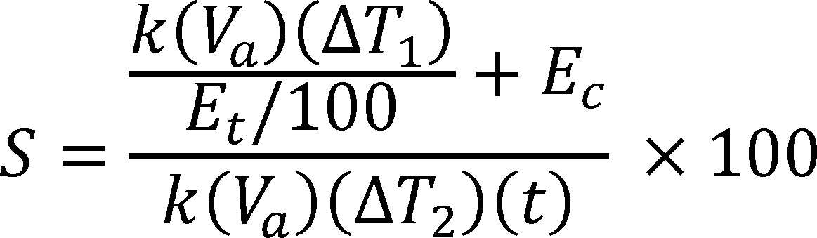
Where,
ΔT1 = Heat exchanger outlet water temperature (TOHX) measured after the pump purge operation is complete (if the unit is integrated with pump purge functionality); or after the main heating element(s) cut-out (if the unit is not equipped with pump purge functionality) minus heat exchanger outlet water temperature (TOHX) measured at the end of the test, expressed in °F
ΔT2 = Heat exchanger outlet water temperature (TOHX) minus the ambient room temperature, both measured after the main heating element(s) cut-out at the start of the test, expressed in °F
k = 8.25 Btu/gallon· °F, the nominal specific heat of water
Va = Volume of water contained in the water heater in gallons measured in accordance with section 4 of this appendix
Et = Thermal efficiency = 98 percent for electric water heaters with immersed heating elements
Ec = Electrical energy consumed by the water heater during the duration of the test in Btu
t = Total duration of the test in hours
S = Standby loss, the average hourly energy required to maintain the stored water temperature expressed as a percentage of the initial heat content of the stored water above room temperature
[81 FR 79340, Nov. 10, 2016]
Appendix E to Subpart G of Part 431—Uniform Test Method for the Measurement of Energy Efficiency of Commercial Heat Pump Water Heaters
Note: On and after November 6, 2017, manufacturers must make any representations with respect to energy use or efficiency of commercial heat pump water heaters in accordance with the results of testing pursuant to this appendix.
1. General. Determine the COPh for commercial heat pump water heaters (CHPWHs) using the test procedure set forth below. Certain sections below reference ANSI/ASHRAE 118.1-2012 (incorporated by reference; see § 431.105). Where the instructions contained below differ from those contained in ANSI/ASHRAE 118.1-2012, the sections in this appendix control.
2. Definitions and Symbols. The definitions and symbols are as listed in section 3 of ANSI/ASHRAE 118.1-2012.
3. Instrumentation. The instruments required for the test are as described in section 6 of ANSI/ASHRAE 118.1-2012 (except sections 6.3, 6.4, and 6.6).
4. Test Set-Up. Follow the provisions described in this section to install the CHPWH for testing. Use the test set-up and installation instructions set forth for Type IV and Type V equipment (as applicable), defined in sections 4.4 and 4.5 of ANSI/ASHRAE 118.1-2012 and in accordance with the sections below:
4.
1. Test set-up and installation instructions.
4.1.1. For air-source CHPWHs, set up the unit for testing as per section 7.1 and Figure 5a of ANSI/ASHRAE 118.1-2012 for CHPWHs without an integral storage tank, and as per Figure 6 in section 7.7.1 of ANSI/ASHRAE 118.1-2012 for CHPWHs with an integral storage tank.
4. 1.2. For direct geo-exchange CHPWHs, set up the unit for testing as per section 7.1 and Figure 5b of ASNI/ASHRAE 118.1-2012 for CHPWHs without an integral storage tank, and as per Figure 7 in section 7.7.2 of ANSI/ASHRAE 118.1-2012 for CHPWHs with an integral storage tank.
4. 1.3. For indoor water-source, ground-source closed-loop, and ground water-source CHPWHs, set up the unit for testing as per section 7.1 and Figure 5c of ANSI/ASHRAE 118.1-2012 for CHPWHs without an integral storage tank, and as per Figure 8 in section 7.7.3 of ANSI/ASHRAE 118.1-2012 for CHPWHs with an integral storage tank.
4. 2. Use the water piping instructions described in section 7.2 of ANSI/ASHRAE 118.1-2012 and the special instructions described in section 7.7.6 of ANSI/ASHRAE 118.1-2012. Insulate all the pipes used for connections with material having a thermal resistance of not less than 4 h· °F·ft2/Btu for a total piping length of not less than 4 feet from the water heater connection ports.
4.3. Install the thermocouples, including the room thermocouples, as per the instructions in sections 7.3.1, 7.3.2, and 7.3.3 (as applicable) of ANSI/ASHRAE 118.1-2012.
4.4. Section 7.6 of ANSI/ASHRAE 118.1-2012 must be used if the manufacturer neither submits nor specifies a water pump applicable for the unit for laboratory testing.
4.5. Install the temperature sensors at the locations specified in Figure 5a, 5b, 5c, 6, 7, or 8 of ANSI/ASHRAE 118.1-2012, as applicable as per section 4.1 of this appendix. The sensor shall be installed in such a manner that the sensing portion of the device is positioned within the water flow and as close as possible to the center line of the pipe. Follow the instructions provided in sections 7.7.7.1 and 7.7.7.2 of ANSI/ASHRAE 118.1-2012 to install the temperature and flow-sensing instruments.
4.6. Use the following evaporator side rating conditions as applicable for each category of CHPWHs. These conditions are also mentioned in Table 5.1 of this appendix:
4.6.1. For air-source CHPWHs, maintain the evaporator air entering dry-bulb temperature at 80.6 °F ± 1 °F and wet-bulb temperature at 71.2 °F ± 1 °F throughout the conduct of the test.
4.6.2. For direct geo-exchange CHPWHs, maintain the evaporator refrigerant temperature at 32 °F ± 1 °F.
4.6.3. For indoor water-source CHPWHs, maintain the evaporator entering water temperature at 68 °F ± 1 °F.
4.6.4. For ground water-source CHPWHs, maintain the evaporator entering water temperature at 50 °F ± 1 °F.
4.6.5. For ground-source closed-loop CHPWHs, maintain the evaporator entering water temperature at 32 °F ± 1 °F.
4.6.5.1. For ground-source closed-loop CHPWHs, the evaporator water must be mixed with 15-percent methanol by-weight to allow the solution to achieve the rating conditions required in section 4.6.5.
4.7. The CHPWH being tested must be installed as per the instructions specified in sections 4.1 to 4.6 (as applicable) of this appendix. For all other installation requirements, use section 7.7.4 of ANSI/ASHRAE 118.1-2012 to resolve any issues related to installation (other than what is specified in this test procedure) of the equipment for testing. Do not make any alterations to the equipment except as specified in this appendix for installation, testing, and the attachment of required test apparatus and instruments.
4. 8. Use Table 3 of ANSI/ASHRAE 118.1-2012 for measurement tolerances of various parameters.
4.9. If the CHPWH is equipped with a thermostat that is used to control the throttling valve of the equipment, then use the provisions in section 7.7.7.3 of ANSI/ASHRAE 118.1-2012 to set up the thermostat.
4.10. For CHPWHs equipped with an integral storage tank, supplemental heat inputs such as electric resistance elements must be disabled as per section 7.7.8 of ANSI/ASHRAE 118.1-2012.
4.11. Install instruments to measure the electricity supply to the equipment as specified in section 7.5 of ANSI/ASHRAE 118.1-2012.
5. Test Procedure
Test all CHPWHs that are not equipped with an integral storage tank as per the provisions described in ANSI/ASHRAE 118.1-2012 for “Type IV” equipment as defined in section 4.4 of ANSI/ASHRAE 118.1-2012. Test all CHPWHs that are equipped with an integral storage tank as per the provisions described in ANSI/ASHRAE 118.1-2012 for “Type V” equipment as defined in section 4.5 of ANSI/ASHRAE 118.1-2012. Tests for all CHPWHs must follow the steps described below.
5.1. Supply the CHPWH unit with electricity at the voltage specified by the manufacturer. Follow the provisions in section 8.2.1 of ANSI/ASHRAE 118.1-2012 to maintain the electricity supply at the required level.
5.1.1. For models with multiple voltages specified by the manufacturer, use the minimum voltage specified by the manufacturer to conduct the test. Maintain the voltage as per the limits specified in section 8.2.1 of ANSI/ASHRAE 118.1-2012. The test may be repeated at other voltages at the manufacturer's discretion.
5.2. Set the condenser supply water temperature and outlet water temperature per the following provisions and as set forth in Table 5.1 of this section:
Table 5.1—Evaporator and Condenser Side Rating Conditions
| Category of CHPWH | Evaporator side rating conditions | Condenser side rating conditions |
|---|---|---|
| Air-source commercial heat pump water heater | Evaporator entering air conditions:
Dry bulb: 80.6 °F ± 1 °F Wet bulb: 71.2 °F ± 1 °F |
Entering water temperature: 70 °F ± 1 °F. Vary water flow rate (if needed) to achieve the outlet water temperature as specified in section 8.7.2 of ANSI/ASHRAE 118.1-2012. |
| If the required outlet water temperature as specified in section 8.7.2 of ANSI/ASHRAE 118.1-2012 is not met even after varying the flow rate, then change the condenser entering water temperature to 110 °F ± 1 °F. Vary flow rate to achieve the conditions in section 8.7.2 of ANSI/ASHRAE 118.1-2012. | ||
| Direct geo-exchange commercial heat pump water heater | Evaporator refrigerant temperature: 32 °F ± 1 °F | Entering water temperature: 110 °F ± 1 °F. |
| Indoor water-source commercial heat pump water heater | Evaporator entering water temperature: 68 °F ± 1 °F | Entering water temperature: 110 °F ± 1 °F. |
| Ground water-source commercial heat pump water heater | Evaporator entering water temperature: 50 °F ± 1 °F | Entering water temperature: 110 °F ± 1 °F. |
| Ground-source closed-loop commercial heat pump water heater | Evaporator entering water temperature: 32 °F ± 1 °F | Entering water temperature: 110 °F ± 1 °F. |
5.2.1. For air-source CHPWHs:
5.2.1.1. Set the supply water temperature to 70 °F ± 1 °F. The water pressure must not exceed the maximum working pressure rating for the equipment under test.
5.2.1.2. Use the provisions in section 8.7.1 of ANSI/ASHRAE 118.1-2012 to set the tank thermostat for CHPWHs equipped with an integral storage tank.
5.2.1.3. Initiate operation at the rated pump flow rate and measure the outlet water temperature. If the outlet water temperature is maintained at 120 °F ± 5 °F with no variation in excess of 2 °F over a three-minute period, as required by section 8.7.2 of ANSI/ASHRAE 118.1-2012, skip to section 5.3 of this appendix.
5.2.1.4. If the outlet water temperature condition as specified in section 8.7.2 of ANSI/ASHRAE 118.1-2012 is not achieved, adjust the water flow rate over the range of the pump's capacity. If, after varying the water flow rate, the outlet water temperature is maintained at 120 °F ± 5 °F with no variation in excess of 2 °F over a three-minute period, as required by section 8.7.2 of ANSI/ASHRAE 118.1-2012, skip to section 5.3 of this appendix.
5.2.1.5. If, after adjusting the water flow rate within the range that is achievable by the pump, the outlet water temperature condition as specified in section 8.7.2 of ANSI/ASHRAE 118.1-2012 is still not achieved, then change the supply water temperature to 110 °F ± 1 °F and repeat the instructions from sections 5.2.1.2 and 5.2.1.4 of this appendix.
5.2.1. 6. If the outlet water temperature condition cannot be met, then a test procedure waiver is necessary to specify an alternative set of test conditions.
5.2.2. For direct geo-exchange, indoor water-source, ground-source closed-loop, and ground water-source CHPWHs use the following steps:
5.2.2.1. Set the condenser supply water temperature to 110 °F ± 1 °F. The water pressure must not exceed the maximum working pressure rating for the equipment under test.
5.2.2.2. Use the provisions in section 8.7.1 of ANSI/ASHRAE 118.1-2012 to set the tank thermostat for CHPWHs equipped with an integral storage tank.
5.2.2.3. Follow the steps specified in section 8.7.2 of ANSI/ASHRAE 118.1-2012 to obtain an outlet water temperature of 120 °F ± 5 °F with no variation in excess of 2 °F over a three-minute period.
5.3. Conduct the test as per section 9.1.1, “Full Input Rating,” of ANSI/ASHRAE 118.1-2012. The flow rate, “FR,” referred to in section 9.1.1 of ANSI/ASHRAE 118.1-2012 is the flow rate of water through the CHPWH expressed in gallons per minute obtained after following the steps in section 5.2 of this appendix. Use the evaporator side rating conditions specified in section 4.6 of this appendix to conduct the test as per section 9.1.1 of ANSI/ASHRAE 118.1-2012.
5.4. Calculate the COPh of the CHPWH according to section 10.3.1 of the ANSI/ASHRAE 118.1-2012 for the “Full Capacity Test Method.” For all calculations, time differences must be expressed in minutes.
[81 FR 79346, Nov. 10, 2016]