Subpart G - Ductwork and Plumbing and Fuel Supply Systems
§ 3285.601 Field assembly.
Home manufacturers must provide specific installation instructions for the proper field assembly of manufacturer-supplied and shipped loose ducts, plumbing, and fuel supply system parts that are necessary to join all sections of the home and are designed to be located underneath the home. The installation instructions must be designed in accordance with applicable requirements of part 3280, subparts G and H, of this chapter, as specified in this subpart.
§ 3285.602 Utility connections.
Refer to § 3285.904 for considerations for utility system connections.
§ 3285.603 Water supply.
(a) Crossover. Multi-section homes with plumbing in both sections require water-line crossover connections to join all sections of the home. The crossover design requirements are located in, and must be designed in accordance with, § 3280.609 of this chapter.
(b) Maximum supply pressure and reduction. When the local water supply pressure exceeds 80 psi to the manufactured home, a pressure-reducing valve must be installed.
(c) Mandatory shutoff valve.
(1) An identified and accessible shutoff valve must be installed between the water supply and the inlet.
(2) The water riser for the shutoff valve connection must be located underneath or adjacent to the home.
(3) The shutoff valve must be a full-flow gate or ball valve, or equivalent valve.
(d) Freezing protection. Water line crossovers completed during installation must be protected from freezing. The freeze protection design requirements are located in, and must be designed in accordance with, § 3280.603 of this chapter.
(1) If subject to freezing temperatures, the water connection must be wrapped with insulation or otherwise protected to prevent freezing.
(2) In areas subject to freezing or subfreezing temperatures, exposed sections of water supply piping, shutoff valves, pressure reducers, and pipes in water heater compartments must be insulated or otherwise protected from freezing.
(3) Use of pipe heating cable. Only pipe heating cable listed for manufactured home use is permitted to be used, and it must be installed in accordance with the cable manufacturer installation instructions.
(e) Testing procedures.
(1) The water system must be inspected and tested for leaks after completion at the site. The installation instructions must provide testing requirements that are consistent with § 3280.612 of this chapter.
(2) The water heater must be disconnected when using an air-only test.
§ 3285.604 Drainage system.
(a) Crossovers. Multi-section homes with plumbing in more than one section require drainage system crossover connections to join all sections of the home. The crossover design requirements are located in, and must be designed in accordance with, § 3280.610 of this chapter.
(b) Assembly and support. If portions of the drainage system were shipped loose because they were necessary to join all sections of the home and designed to be located underneath the home, they must be installed and supported in accordance with § 3280.608 of this chapter.
(c) Proper slopes. Drains must be completed in accordance with § 3280.610 of this chapter.
(1) Drain lines must not slope less than one-quarter inch per foot, unless otherwise noted on the schematic diagram, as shown in Figure to § 3285.604.
(2) A slope of one-eight inch per foot may be permitted when a clean-out is installed at the upper end of the run.
(d) Testing procedures. The drainage system must be inspected and tested for leaks after completion at the site. The installation instructions must provide testing requirements that are consistent with § 3280.612 of this chapter.

§ 3285.605 Fuel supply system.
(a) Proper supply pressure. The gas piping system in the home is designed for a pressure that is at least 7 inches of water column [4oz./in.2 or 0.25 psi] and not more than 14 inches of water column [8 oz./in.2 or 0.5 psi]. If gas from any supply source exceeds, or could exceed this pressure, a regulator must be installed if required by the LAHJ.
(b) Crossovers.
(1) Multi-section homes with fuel supply piping in both sections require crossover connections to join all sections of the home. The crossover design requirements are located in, and must be designed in accordance with, § 3280.705 of this chapter.
(2) Tools must not be required to connect or remove the flexible connector quick-disconnect.
(c) Testing procedures. The gas system must be inspected and tested for leaks after completion at the site. The installation instructions must provide testing requirements that are consistent with § 3280.705 of this chapter.
§ 3285.606 Ductwork connections.
(a) Multi-section homes with ductwork in more than one section require crossover connections to complete the duct system of the home. All ductwork connections, including duct collars, must be sealed to prevent air leakage. Galvanized metal straps or tape and mastics listed to UL 181A (incorporated by reference, see § 3285.4), for closure systems with rigid air ducts and connectors, or UL 181B (incorporated by reference, see § 3285.4), for closure systems with flexible air ducts and connectors, must be used around the duct collar and secured tightly to make all connections.
(b) If metal straps are used, they must be secured with galvanized sheet metal screws.
(c) Metal ducts must be fastened to the collar with a minimum of three galvanized sheet metal screws equally spaced around the collar.
(d) Air conditioning or heating ducts must be installed in accordance with applicable requirements of the duct manufacturer installation instructions.
(e) The duct must be suspended or supported above the ground by straps or other means that are spaced at a maximum distance not to exceed 4′-0″ or as otherwise permitted by the installation instructions. When straps are used to support a flexible type duct, the straps must be at least 1⁄2″ wider than the spacing of the metal spirals encasing the duct. The ducts must be installed such that the straps cannot slip between any two spirals and arranged under the floor to prevent compression or kinking in any location, as shown in Figures A and B to this section. In-floor crossover ducts are permitted, in accordance with § 3285.606(g).
(f) Crossover ducts outside the thermal envelope must be insulated with materials that conform to designs consistent with part 3280, subpart F of this chapter.
(g) In-floor or ceiling crossover duct connections must be installed and sealed to prevent air leakage.
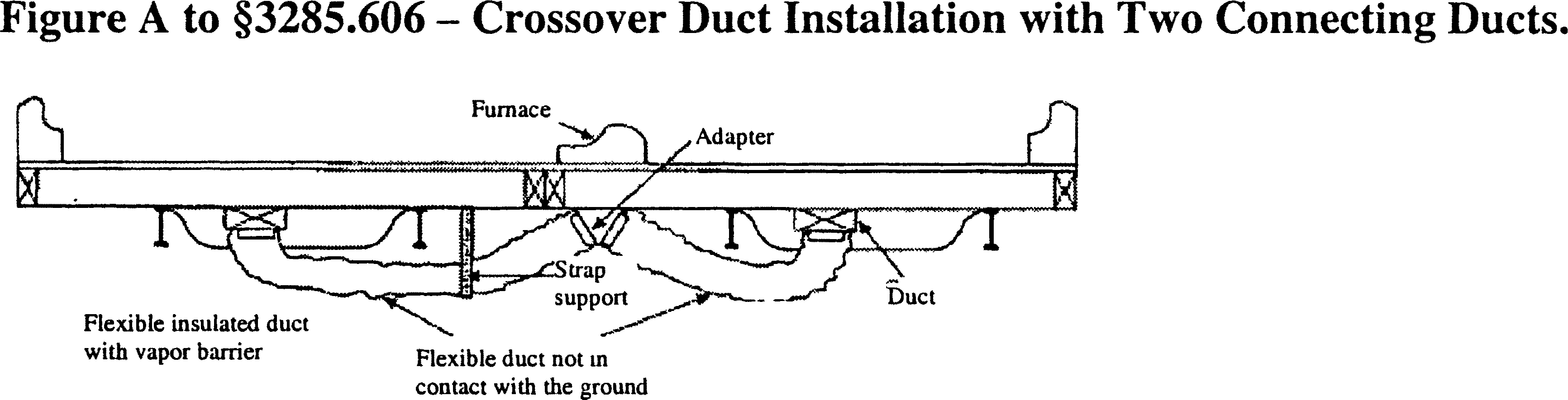
1. This system is typically used when a crossover duct has not been built into the floor and the furnace is outside the I-Beam. With this type of installation, it is necessary for two flexible ducts to be installed.
2. The crossover duct must be listed for exterior use.

1. This system is typically used when a crossover duct has not been built into the floor and the furnace is situated directly over the main duct in one section of the home. A single flexible duct is then used to connect the two sections to each other.
2. The crossover duct must be listed for exterior use.