PART 222 - ENGINEERING AND DESIGN
§ 222.2 Acquisition of lands downstream from spillways for hydrologic safety purposes.
(a) Purpose. This regulation provides guidance on the acquisition of lands downstream from spillways for the purpose of protecting the public from hazards imposed by spillway discharges. Guidance contained herein is in addition to ER 405-2-150.
(b) Applicability. This regulation is applicable to all OCE elements and all field operating agencies having civil works responsibilities.
(c) Reference. ER 405-2-150.
(d) Discussion. A policy of public safety awareness will be adhered to in all phases of design and operation of dam and lake projects to assure adequate security for the general public in areas downstream from spillways. A real estate interest will be required in those areas downstream of a spillway where spillway discharge could create or significantly increase a hazardous condition. The real estate interest will extend downstream to where the spillway discharge would not significantly increase hazards. A real estate interest is not required in areas where flood conditions would clearly be nonhazardous.
(e) Hydrologic criteria. The construction and operation of a dam and spillway may create or aggravate a potential hazard in the spillway discharge area. Therefore, an appropriate solution should be developed in a systematic manner. All pertinent facts need to be considered to assure that the risk to non-Federal interests does not exceed conditions that would prevail without the project. General hydrologic engineering considerations are as follows:
(1) Probability of spillway use. Pool elevation versus probability of filling relationships can change materially after initial construction. Spillway use may be more frequent than anticipated. The infrequent use of a spillway is not a basis for the lack of adequate downstream real estate interest.
(2) Changes in project functions. Water resource needs within river basins change and pool levels may be adjusted to provide more conservation storage, particularly when high-level limited-service spillways are provided. Such changes normally increase spillway use and are to be considered.
(3) Volume and velocity of spillway flow. The amount of flow and destructive force of the flow from a spillway during floods up to the spillway design flood can vary from insignificant to extremely hazardous magnitudes. The severity and area of hazard associated with spillway discharge will vary depending on specific project site conditions. Therefore, the hazard is to be analyzed on a project-by-project basis.
(4) Development within floodway. If development within the floodway downstream from a spillway is not present at the time of project construction, the existence of the reservoir may encourage development. Adverse terrain conditions do not preclude development. Sparse present development is not a basis for lack of real estate acquisition.
(5) Debris movement within floodway. The availability of erodible material in a spillway flow area intensifies the hazards of spillway flow. In fact, debris may be transported to downstream areas that otherwise would not be adversely affected. Extreme erosion may result from high velocities and turbulence. Both debris and erosion must be evaluated and considered.
(6) Flood warning and response potential. Small projects generally have short time periods available to warn downstream inhabitants and may be unattended prior to spillway use. The ability to convince individuals to leave most of their worldly possessions to the ravages of spillway flow may be severely limited. In some cases flood warning systems may be necessary; however, this subject is beyond the scope of this regulation. Warning systems are not an adequate substitute for a real estate interest in lands downstream of spillways.
(7) Location of spillway. Spillways should be located to minimize the hazards associated with their discharge and the total project cost (cost of spillway structure and downstream lands). Spillways, outlet works, stilling basins, and outlet channels should be designed to minimize hazards to downstream interest insofar as is engineeringly and economically reasonable.
(f) Real estate. The real estate interest required downstream of spillways will be adequate to assure carrying out project purposes and to protect non-Federal interest from hazards created by spillway flows. The interest may be either fee or permanent easement. A permanent easement must exclude all overnight and/or permanent habitation, structures subject to damage by spillway flows and activities that would increase the potential hazards. No real estate interest is required for:
(1) Areas where the imposed or aggravated flood condition is non-hazardous. Affected interest should be informed of the nature of the imposed non-hazardous flood condition.
(2) Areas where the construction and operation of a dam and spillway do not increase or create a hazardous condition.
(g) Alternative land uses. In some cases land downstream from spillways can be effectively used for purposes other than hydrologic safety. Therefore, the entire cost of these lands may not be an additional project cost. For example, the lands downstream of a spillway may be used for wildlife management essential to project purposes in lieu of other lands suitable for similar purposes at another location.
(h) Procedural guidance. Procedures regarding the application of the principles outlined in the above paragraphs are as follows:
(1) For various flood magnitudes up to the probable maximum flood determine the “with” and “without project” flood conditions downstream of a dam spillway for the following:
(i) Flooded area.
(ii) Flood depth.
(iii) Flood duration.
(iv) Velocities.
(v) Debris and erosion.
(2) Determine the combinations of flood magnitudes and the above flood conditions that could be the most hazardous and/or result in the greatest increase in hazard from “without” to “with project” flood conditions. Designate these combinations of flood magnitude and flood conditions as the critical conditions.
(3) For the critical conditions selected above outline the areas where the project could increase and/or create (impose) one or more of the critical conditions. Areas where spillway flows do not create or increase flood conditions are excluded from further analysis.
(4) Determine where the imposed critical conditions as outlined above would be hazardous and non-hazardous. Non-hazardous areas are defined as those areas where:
(i) Flood depths are maximum of 2 feet in urban and rural areas.
(ii) Flood depths are essentially non-damaging to urban property.
(iii) Flood durations are a maximum of 3 hours in urban areas and 24 hours in agricultural areas.
(iv) Velocities do not exceed 4 feet per second.
(v) Debris and erosion potentials are minimal.
(vi) Imposed flood conditions would be infrequent. That is, the exceedence frequency should be less than 1 percent. Hazardous areas are those where any of the above criteria are exceeded.
(5) Based upon the information developed above and the principles outlined in paragraphs (c) through (f) of this section, decide on the extent of area and estate required for hydrologic safety purposes.
(i) Reporting. Lands to be acquired downstream from spillways and intended purposes will be identified and the cost included in feasibility reports and real estate design memoranda. Additional specific information in support of land acquisition should be provided in Phase I or Phase II general design memoranda (GDM) and dam modernization reports. This information should include topographic maps, area flooded maps, velocities, erosion and debris areas “with” and “without” the project. Real estate boundaries and discussions of items in paragraph (h)(4) are also essential in the GDM's and dam modernization reports.
[43 FR 35481, Aug. 10, 1978. Redesignated at 60 FR 19851, Apr. 21, 1995]
§ 222.3 Clearances for power and communication lines over reservoirs.
(a) Purpose. This regulation prescribes the minimum vertical clearances to be provided when relocating existing or constructing new power and communication lines over waters of reservoir projects.
(b) Applicability. This regulation applies to all field operating agencies having Civil Works responsibilities.
(c) References.
(1) ER 1180-1-1 (Section 73).
(2) National Electrical Safety Code (ANSI C2), available from IEEE Service Center, 445 Hoes Lane, Piscataway, N.J. 08854.
(d) Definitions —
(1) Design high water level. The design high water level above which clearances are to be provided shall be either:
(i) The elevation of the envelope profile of the 50 year flood, or flood series, routed through the reservoir with a full conservation pool after 50 years of sedimentation, or
(ii) the elevation of the top of the flood control pool, whichever is higher.
(2) Low point of line. The low point of the line shall be the elevation of the lowest point of the line taking into consideration all factors including temperature, loading and length of spans as outlined in the National Electrical Safety Code.
(3) Minimum vertical clearance. The minimum vertical clearance shall be the distance from the design high water lever (paragraph (d)(1) of this section) to the low point of the line (paragraph (d)(2) of this section).
(e) Required clearances. Minimum vertical clearances for power and communication lines over reservoirs shall not be less than required by section 23, rule 232 of the latest revision of the National Electrical Safety Code (ANSI C2).
(1) In general, minimum vertical clearances shall not be less than shown in Table 232-1, Item 7, of ANSI C2, even for reservoirs or areas not suitable for sailboating or where sailboating is prohibited.
(2) If clearances not in accordance with Table 232-1 of ANSI C2 are proposed, justification for the clearances should be provided.
(f) Navigable waters. For parts of reservoirs that are designated as navigable waters of the United States, greater clearances will be provided if so required. The clearances required over navigable waters are covered by 33 CFR 322.5(i)(2) and are not affected by this regulation.
[43 FR 14013, Apr. 4, 1978. Redesignated at 60 FR 19851, Apr. 21, 1995]
§ 222.4 Reporting earthquake effects.
(a) Purpose. This regulation states policy, defines objectives, assigns functions, and establishes procedures for assuring the structural integrity and operational adequacy of major Civil Works structures following the occurrence of significant earthquakes. It primarily concerns damage surveys following the occurrences of earthquakes.
(b) Applicability. This regulation is applicable to all field operating agencies having Civil Works responsibilities.
(c) References.
(1) ER 1110-2-100 (§ 222.2).
(2) ER 1110-2-1806.
(3) ER 1110-2-8150.
(4) ER 1130-2-419.
(5) State-of-the-Art for Assessing Earthquake Hazards in the United States—WES Miscellaneous Papers S-73-1—Reports 1 thru 14. Available from U.S. Army Engineer Waterways Experiment Station, P.O. Box 631, Vicksburg, Mississippi 39180.
(d) Policy. Civil Works structures which could be caused to fail or partially fail by an earthquake and whose failure or partial failure would endanger the lives of the public and/or cause substantial property damage, will be evaluated following potentially damaging earthquakes to insure their continued structural stability, safety and operational adequacy. These structures include dams, navigation locks, powerhouses, and appurtenant structures, (intakes, outlet works, buildings, tunnels, paved spillways) which are operated by the Corps of Engineers and for which the Corps is fully responsible. Also included are major levees, floodwalls, and similar facilities designed and constructed by the Corps of Engineers and for whose structural safety and stability the Corps has a public obligation to be aware of although not responsible for their maintenance and operation. The evaluation of these structures will be based upon post-earthquake inspections which will be conducted to detect conditions of significant structural distress and to provide a basis for timely initiation of restorative and remedial measures.
(e) Post-earthquake inspections and evaluation surveys —
(1) Limitations of present knowledge. The design of structures for earthquake loading is limited by the infrequent opportunity to compare actual performance with the design. Damage which would affect the function of the project is unlikely if peak accelerations are below 0.1g.; but it cannot be assumed that a structure will not be damaged from earthquake loadings below that for which it was designed. Furthermore, earthquakes have occurred in several parts of the country where significant seismic activity had not been predicted by some seismic zoning maps. This indicates the possibility that earthquake induced loads may not have been adequately considered in the design of older structures.
(2) Types of reportable damage. Many types of structural damage can be induced by ground motion from earthquakes or from large nuclear blasts (which also tend to induce ground vibrations in the more damaging lower frequency ranges). Any post-earthquake change in appearance or functional capability of a major Civil Works structure should be evaluated and reported. Examples are symptoms of induced stresses in buildings made evident by cracked plaster, windows or tile, or in binding of doors or windows; cracked or shifted bridge pier footings or other concrete structures; turbidity or changed static level of water wells; cracks in concrete dams or earth embankments; and misalignment of hydraulic control structures or gates. Induced dynamic loading on earth dams may result in loss of freeboard by settlement, or cause localized quick conditions within the embankment sections or earth foundations. Also, new seepage paths may be opened up within the foundation or through the embankment section. Ground motion induced landslides may occur in susceptible areas of the reservoir rim, causing embankment overtopping by waves and serious damage. All such unusual conditions should be evaluated and reported.
(f) Inspection and evaluation programs.
(1) If the project is located in an area where the earthquake causes significant damage (Modified Mercalli Intensity VII or greater) to structures in the vicinity, the Chief, Engineering Division, should be immediately notified and an engineering evaluation and inspection team should be sent to the project.
(2) If the project is located in an area where the earthquake is felt but causes no or insignificant damage (Modified Mercalli Intensity VI or less) to structures in the vicinity of the project, project operations personnel should make an immediate inspection. This inspection should determine:
(i) Whether there is evidence of earthquake damage or disturbance, and
(ii) whether seismic instrumentation, where present, has been triggered. The Chief, Engineering Division should be notified by phone of the results of the inspection. If damage is observed, which is considered to threaten the immediate safety or operational capability of the project, immediate action should be taken as covered in paragraph (f)(1) of this section. For other situations, the Chief of Engineering Division will determine the need for and urgency for an engineering inspection.
(3) When an engineering inspection of structures is deemed necessary following a significant earthquake, HQDA (DAEN-CWE) WASH DC 20314 will be notified of the inspection program as soon as it is established.
(4) As a general rule, the structures which would be of concern following an earthquake are also the structures which are involved in the inspection program under ER 1110-2-100. Whenever feasible, instrumentation and prototype testing programs undertaken under ER 1110-2-100 to monitor structural performance and under ER 1110-2-8150 to develop design criteria will be utilized in the post-earthquake safety evaluation programs. Additional special types of instrumentation will be incorporated in selected structures in which it may be desirable to measure forces, pressures, loads, stresses, strains, displacements, deflections, or other conditions relating to damage and structural safety and stability in case of an earthquake.
(5) Where determined necessary, a detailed, systematic engineering inspection will be made of the post-earthquake condition of each structure, taking into account its distinctive features. For structures which have incurred earthquake damage a formal technical report will be prepared in a format similar to inspection reports required under ER 1110-2-100. (Exempt from requirements control under paragraph 7-2b, AR 335-15.) The report will include summaries of the instrumentation and other observation data for each inspection, for permanent record and reference purposes. This report will be used to form a basis for major remedial work when required. Where accelerometers or other types of strong motion instruments have been installed, readings and interpretations from these instruments should also be included in the report. The report will contain recommendations for remedial work when appropriate, and will be transmitted through the Division Engineer for review and to HQDA (DAEN-CWE) WASH DC 20314 for review and approval. For structures incurring no damage a simple statement to this effect will be all that is required in the report, unless seismic instrumentation at the project is activated. (See paragraph (h)(4) of this section.)
(g) Training. The dam safety training program covered by paragraph 6 of ER 1130-2-419 should include post-earthquake inspections and the types of damage operations personnel should look for.
(h) Responsibilities.
(1) The Engineering Divisions of the District offices will formulate the inspection program, conduct the post-earthquake inspections, process and analyze the data of instrumental and other observations, evaluate the resulting condition of the structures, and prepare the inspection reports. The Engineering division is also responsible for planning special instrumentation felt necessary in selected structures under this program. Engineering Division is responsible for providing the training discussed in paragraph (g) of this section.
(2) The Construction Divisions of the District offices will be responsible for the installation of the earthquake instrumentation devices and for data collection if an earthquake occurs during the construction period.
(3) The Operations Division of the District offices will be responsible for the immediate assessment of earthquake damage and notifying the Chief, Engineering Division as discussed in paragraphs (f)(1) and (2). The Operations Division will also be responsible for earthquake data collection after the construction period in accordance with the instrumental observation programs, and will assist and participate in the post-earthquake inspections.
(4) The U.S. Geological Survey has the responsibility for servicing and collecting all data from strong motion instrumentation at Corps of Engineers dam projects following an earthquake occurrence. However, the U.S. Army Waterways Experiment Station (WES) is assigned the responsibility for analyzing and interpreting these earthquake data. Whenever a recordable earthquake record is obtained from seismic instrumentation at a Corps project, the Division will send a report of all pertinent instrumentation data to the Waterways Experiment Station, ATTN: WESGH, P.O. Box 631, Vicksburg, Mississippi 39180. The report on each project should include a complete description of the locations and types of instruments and a copy of the instrumental records from each of the strong motion machines activated. (Exempt from requirements control under paragraph 7-2v, AR 335-15).
(5) The Engineering Divisions of the Division offices will select structures for special instrumentation for earthquake effects, and will review and monitor the data collection, processing, evaluating, and inspecting activities. They will also be specifically responsible for promptly informing HQDA (DAEN-CWE) WASH DC 20314, when evaluation of the condition of the structure or analyses of the instrumentation data indicate the stability of a structure is questionable. (Exempt for requirements control under paragraph 7-2o, AR 335-15.)
(6) Division Engineers are responsible for issuing any supplementary regulations necessary to adapt the policies and instructions herein to the specific conditions within their Division.
(i) Funding. Funding for the evaluation and inspection program will be under the Appropriation 96X3123, Operations and Maintenance, General. Funds required for the inspections, including Travel and Per Diem costs incurred by personnel of the Division office or the Office, Chief of Engineers, will be from allocations made to the various projects for the fiscal year in which the inspection occurs.
[44 FR 43469, July 25, 1979. Redesignated at 60 FR 19851, Apr. 21, 1995]
§ 222.5 Water control management (ER 1110-2-240).
(a) Purpose. This regulation prescribes policies and procedures to be followed by the U.S. Army Corps of Engineers in carrying out water control management activities, including establishment of water control plans for Corps and non-Corps projects, as required by Federal laws and directives.
(b) Applicability. This regulation is applicable to all field operating activities having civil works responsibilities.
(c) References. Appendix A lists U.S. Army Corps of Engineers publications and sections of Federal statutes and regulations that are referenced herein.
(d) Authorities —
(1) U.S. Army Corps of Engineers projects. Authorities for allocation of storage and regulation of projects owned and operated by the Corps of Engineers are contained in legislative authorization acts and referenced project documents. These public laws and project documents usually contain provisions for development of water control plans, and appropriate revisions thereto, under the discretionary authority of the Chief of Engineers. Some modifications in project operation are permitted under congressional enactments subsequent to original project authorization. Questions that require interpretations of authorizations affecting regulation of specific reservoirs will be referred to CDR USACE (DAEN-CWE-HW), WASH DC 20314, with appropriate background information and analysis, for resolution.
(2) Non-Corps projects. The Corps of Engineers is responsible for prescribing flood control and navigation regulations for certain reservoir projects constructed or operated by other Federal, non-Federal or private agencies. There are several classes of such projects: Those authorized by special acts of Congress; those for which licenses issued by the Federal Energy Regulatory Commission (formerly Federal Power Commission) provide that operation shall be in accordance with instructions of the Secretary of the Army; those covered by agreements between the operating agency and the Corps of Engineers; and those that fall under the terms of general legislative and administrative provisions. These authorities, of illustrative examples, are described briefly in Appendix B.
(e) Terminology: Water control plans and reservoir regulation schedules.
(1) Water control plans include coordinated regulation schedules for project/system regulation and such additional provisions as may be required to collect, analyze and disseminate basic data, prepare detailed operating instructions, assure project safety and carry out regulation of projects in an appropriate manner.
(2) The term “reservoir regulation schedule” refers to a compilation of operating criteria, guidelines, rule curves and specifications that govern basically the storage and release functions of a reservoir. In general, schedules indicate limiting rates of reservoir releases required during various seasons of the year to meet all functional objectives of the particular project, acting separately or in combination with other projects in a system. Schedules are usually expressed in the form of graphs and tabulations, supplemented by concise specifications.
(f) General policies.
(1) Water control plans will be developed for reservoirs, locks and dams, reregulation and major control structures and interrelated systems to conform with objectives and specific provisions of authorizing legislation and applicable Corps of Engineers reports. They will include any applicable authorities established after project construction. The water control plans will be prepared giving appropriate consideration to all applicable Congressional Acts relating to operation of Federal facilities, i.e., Fish and Wildlife Coordination Act (Pub. L. 85-624), Federal Water Project Recreation Act-Uniform Policies (Pub. L. 89-72), National Environmental Policy Act of 1969 (Pub. L. 91-190), and Clean Water Act of 1977 (Pub. L. 95-217). Thorough analysis and testing studies will be made as necessary to establish the optimum water control plans possible within prevailing constraints.
(2) Necessary actions will be taken to keep approved water control plans up-to-date. For this purpose, plans will be subject to continuing and progressive study by personnel in field offices of the Corps of Engineers. These personnel will be professionally qualified in technical areas involved and familiar with comprehensive project objectives and other factors affecting water control. Organizational requirements for water control management are further discussed in ER 1110-2-1400.
(3) Water control plans developed for specific projects and reservoir systems will be clearly documented in appropriate water control manuals. These manuals will be prepared to meet initial requirements when storage in the reservoir begins. They will be revised as necessary to conform with changing requirements resulting from developments in the project area and downstream, improvements in technology, new legislation and other relevant factors, provided such revisions comply with existing Federal regulations and established Corps of Engineers policy.
(4) Development and execution of water control plans will include appropriate consideration for efficient water management in conformance with the emphasis on water conservation as a national priority. The objectives of efficient water control management are to produce beneficial water savings and improvements in the availability and quality of water resulting from project regulation/operation. Balanced resource use through improved regulation should be developed to conserve as much water as possible and maximize all project functions consistent with project/system management. Continuous examination should be made of regulation schedules, possible need for storage reallocation (within existing authority and constraints) and to identify needed changes in normal regulation. Emphasis should be placed on evaluating conditions that could require deviation from normal release schedules as part of drought contingency plans (ER 1110-2-1941).
(5) Adequate provisions for collection, analysis and dissemination of basic data, the formulation of specific project regulation directives, and the performance of project regulation will be established at field level.
(6) Appropriate provisions will be made for monitoring project operations, formulating advisories to higher authorities, and disseminating information to others concerned. These actions are required to facilitate proper regulation of systems and to keep the public fully informed regarding all pertinent water control matters.
(7) In development and execution of water control plans, appropriate attention will be given to project safety in accordance with ER 1130-2-417 and ER 1130-2-419 so as to insure that all water impounding structures are operated for the safety of users of the facilities and the general public. Care will be exercised in the development of reservoir regulation schedules to assure that controlled releases minimize project impacts and do not jeopardize the safety of persons engaged in activities downstream of the facility. Water control plans will include provisions for issuing adequate warnings or otherwise alerting all affected interests to possible hazards from project regulation activities.
(8) In carrying out water control activities, Corps of Engineers personnel must recognize and observe the legal responsibility of the National Weather Service (NWS), National Oceanic and Atmospheric Administration (NOAA), for issuing weather forecasts and flood warnings, including river discharges and stages. River forecasts prepared by the Corps of Engineers in the execution of its responsibilities should not be released to the general public, unless the NWS is willing to make the release or agrees to such dissemination. However, release to interested parties of factual information on current storms or river conditions and properly quoted NWS forecasts is permissible. District offices are encouraged to provide assistance to communities and individuals regarding the impact of forecasted floods. Typical advice would be to provide approximate water surface elevations at locations upstream and downstream of the NWS forecasting stream gages. Announcement of anticipated changes in reservoir release rates as far in advance as possible to the general public is the responsibility of Corps of Engineers water control managers for projects under their jurisdiction.
(9) Water control plans will be developed in concert with all basin interests which are or could be impacted by or have an influence on project regulation. Close coordination will be maintained with all appropriate international, Federal, State, regional and local agencies in the development and execution of water control plans. Effective public information programs will be developed and maintained so as to inform and educate the public regarding Corps of Engineers water control management activities.
(10) Fiscal year budget requests for water control management activities will be prepared and submitted to the Office of the Chief of Engineers in accordance with requirements established in Engineer Circular on Annual Budget Requests for Civil Works Activities. The total annual costs of all activities and facilities that support the water control functions, (excluding physical operation of projects, but including flood control and navigation regulation of projects subject to 33 CFR 208.11) are to be reported. Information on the Water Control Data Systems and associated Communications Category of the Plant Replacement and Improvement Program will be submitted with the annual budget. Reporting will be in accordance with the annual Engineer Circular on Civil Works Operations and Maintenance, General Program.
(g) Responsibilities: US Army Corps of Engineers projects —
(1) Preparation of water control plans and manuals. Normally, district commanders are primarily responsible for background studies and for developing plans and manuals required for reservoirs, locks and dams, reregulation and major control structures and interrelated systems in their respective district areas. Policies and general guidelines are prescribed by OCE engineer regulations while specific requirements to implement OCE guidance are established by the division commanders concerned. Master Water Control Manuals for river basins that include more than one district are usually prepared by or under direct supervision of division representatives. Division commanders are responsible for providing such management and technical assistance as may be required to assure that plans and manuals are prepared on a timely and adequate basis to meet water control requirements in the division area, and for pertinent coordination among districts, divisions, and other appropriate entities.
(2) Public involvement and information —
(i) Public meeting and public involvement. The Corps of Engineers will sponsor public involvement activities, as appropriate, to appraise the general public of the water control plan. In developing or modifying water control manuals, the following criteria is applicable.
(A) Conditions that require public involvement and public meetings include: Development of a new water control manual that includes a water control plan; or revision or update of a water control manual that changes the water control plan.
(B) Revisions to water control manuals that are administratively or informational in nature and that do not change the water control plan do not require public meetings.
(C) For those conditions described in paragraph (g)(2)(i)(A) of this section, the Corps will provide information to the public concerning proposed water control management decisions at least 30 days in advance of a public meeting. In so doing, a separate document(s) should be prepared that explains the recommended water control plan or change, and provides technical information explaining the basis for the recommendation. It should include a description of its impacts (both monetary and nonmonetary) for various purposes, and the comparisons with alternative plans or changes and their effects. The plan or manual will be prepared only after the public involvement process associated with its development or change is complete.
(D) For those conditions described in paragraph (g)(2)(i)(A) of this section, the responsible division office will send each proposed water control manual to the Army Corps of Engineers Headquarters, Attn: CECW-EH-W for review and comments prior to approval by the responsible division office.
(ii) Information availability. The water control manual will be made available for examination by the general public upon request at the appropriate office of the Corps of Engineers. Public notice shall be given in the event of occurring or anticipated significant changes in reservoir storage or flow releases. The method of conveying this information shall be commensurate with the urgency of the situation and the lead time available.
(3) Authority for approval of plans and manuals. Division commanders are delegated authority for approval of water control plans and manuals, and associated activities.
(4) OCE role in water control activities. OCE will establish policies and guidelines applicable to all field offices and for such actions as are necessary to assure a reasonable degree of consistency in basic policies and practices in all Division areas. Assistance will be provided to field offices during emergencies and upon special request.
(5) Methods improvement and staff training. Division and district commanders are responsible for conducting appropriate programs for improving technical methods applicable to water control activities in their respective areas. Suitable training programs should be maintained to assure a satisfactory performance capability in water control activities. Appropriate coordination of such programs with similar activities in other areas will be accomplished to avoid duplication of effort, and to foster desirable exchange of ideas and developments. Initiative in re-evaluating methods and guidelines previously established in official documents referred to in paragraph (e) of this section is encouraged where needs are evident. However, proposals for major deviations from basic concepts, policies and general practices reflected in official publications will be submitted to CDR USACE (DAEN-CWE) WASH DC 20314 for concurrence or comment before being adopted for substantial application in actual project regulation at field level.
(h) Directives and technical instruction manuals.
(1) Directives issued through OCE Engineer Regulations will be used to foster consistency in policies and basic practices. They will be supplemented as needed by other forms of communication.
(2) Engineering Manuals (EM) and Engineer Technical Letters (ETL) are issued by OCE to serve as general guidelines and technical aids in developing water control plans and manuals for individual projects or systems.
(3) EM 1110-2-3600 discusses principles and concepts involved in developing water control plans. Instructions relating to preparation of “Water Control Manuals for specific projects” are included. EM 1110-2-3600 should be used as a general guide to water control activities. The instructions are sufficiently flexible to permit adaptation to specific regions. Supplemental information regarding technical methods is provided in numerous documents distributed to field offices as “hydrologic references.”
(4) Special assistance in technical studies is available from the Hydrologic Engineering Center, Corps of Engineers, 609 Second Street, Davis, California 95616 and DAEN-CWE-HW.
(i) Water control manuals for US Army Corps of Engineers projects.
(1) As used herein, the term “water control manual” refers to manuals that relate primarily to the functional regulation of an individual project or system of projects. Although such manuals normally include background information concerning physical features of projects, they do not prescribe rules or methods for physical maintenance or care of facilities, which are covered in other documents. (References 15 and 23, appendix A.)
(2) Water control manuals prepared in substantially the detail and format specified in instructions referred to in paragraph 8 are required for all reservoirs under the supervision of the Corps of Engineers, regardless of the purpose or size of the project. Water Control manuals are also required for lock and dam, reregulation and major control structure projects that are physically regulated by the Corps of Engineers. Where there are several projects in a drainage basin with interrelated purposes, a “Master Manual” shall be prepared. The effects of non-Corps projects will be considered in appropriate detail, including an indication of provisions for interagency coordination.
(3) “Preliminary water control manuals,” for projects regulated by the Corps of Engineers should contain regulation schedules in sufficient detail to establish the basic plan of initial project regulation.
(4) As a general rule, preliminary manuals should be superseded by more detailed interim or “final” manuals within approximately one year after the project is placed in operation.
(5) Each water control manual will contain a section on special regulations to be conducted during emergency situations, including droughts. Preplanned operations and coordination are essential to effective relief or assistance.
(6) One copy of all water control manuals and subsequent revisions shall be forwarded to DAEN-CWE-HW for file purposes as soon as practicable after completion, preferably within 30 days from date of approval at the division level.
(j) Policies and requirements for preparing regulations for non-Corps projects.
(1) Division and district commanders will develop water control plans as required by section 7 of the 1944 Flood Control Act, the Federal Power Act and section 9 of Pub. L. 436-83 for all projects located within their areas, in conformance with ER 1110-2-241, 33 CFR part 208. That regulation prescribes the policy and general procedures for regulating reservoir projects capable of regulation for flood control or navigation, except projects owned and operated by the Corps of Engineers; the International Boundary and Water Commission, United States and Mexico; those under the jurisdiction of the International Joint Commission, United States and Canada, and the Columbia River Treaty. ER 1110-2-241, 33 CFR part 208 permits the promulgation of specific regulations for a project in compliance with the authorizing acts, when agreement on acceptable regulations cannot be reached between the Corps Engineers and the owners. Appendix B provides a summary of the Corps of Engineers responsibilities for prescribing regulations for non-Corps reservoir projects.
(2) Water control plans will be developed and processed as soon as possible for applicable projects already completed and being operated by other entities, including projects built by the Corps of Engineers and turned over to others for operation.
(3) In so far as practicable, water control plans for non-Corps projects should be developed in cooperation with owning/operating agencies involved during project planning stages. Thus, tentative agreements on contents, including pertinent regulation schedules and diagrams, can be accomplished prior to completion of the project.
(4) The magnitude and nature of storage allocations for flood control or navigation purposes in non-Corps projects are governed basically by conditions of project authorizations or other legislative provisions and may include any or all of the following types of storage assignments:
(i) Year-round allocations: Storage remains the same all year.
(ii) Seasonal allocations: Storage varies on a fixed seasonal basis.
(iii) Variable allocations of flood control from year to year, depending on hydrologic parameters, such as snow cover.
(5) Water control plans should be developed to attain maximum flood control or navigation benefits, consistent with other project requirements, from the storage space provided for these purposes. When reservoir storage capacity of the category referred to in paragraph (j)(4)(iii) is utilized for flood control or navigation, jointly with other objectives, the hydrologic parameters and related rules developed under provisions of ER 1110-2-241, 33 CFR part 208 should conform as equitably as possible with the multiple-purpose objectives established in project authorizations and other pertinent legislation.
(6) Storage allocations made for flood control or navigation purposes in non-Corps projects are not subject to modifications by the Corps of Engineers as a prerequisite for prescribing 33 CFR 208.11 regulations. However, regulations developed for use of such storage should be predicated on a mutual understanding between representatives of the Corps and the operating agency concerning the conditions of the allocations in order to assure reasonable achievement of basic objectives intended. In the event field representatives of the Corps of Engineers, and the operating agency are unable to reach necessary agreements after all reasonable possibilities have been explored, appropriate background explanations and recommendations should be submitted to DAEN-CWE-HW for consideration.
(7) The Chief of Engineers is responsible for prescribing regulations for use of flood control or navigation storage and/or project operation under the provisions of the referenced legislative acts. Accordingly, any regulations established should designate the division/district commander who is responsible to the Chief of Engineers as the representative to issue any special instructions required under the regulation. However, to the extent practicable, project regulations should be written to permit operation of the project by the owner without interpretations of the regulations by the designated representative of the Commander during operating periods.
(8) Responsibility for compliance with 33 CFR 208.11 regulations rests with the operating agency. The division or district commander of the area in which the project is located will be kept informed regarding project operations to verify reasonable conformance with the regulations. The Chief of Engineers or his designated representative may authorize or direct deviation from the established water control plan when conditions warrant such deviation. In the event unapproved deviations from the prescribed regulations seem evident, the division or district commander concerned will bring the matter to the attention of the operating agency by appropriate means.
If corrective actions are not taken promptly, the operating agency should be notified of the apparent deviation in writing as a matter of record. Should an impasse arise, in that the project owner or the designated operating entity persists in noncompliance with regulations prescribed by the Corps of Engineers, the Office of Chief Counsel should be advised through normal channels and requested to take necessary measures to assure compliance.
(9) Regulations should contain information regarding the required exchange of basic data between the representative of the operating agency and the U.S. Army Corps of Engineers, that are pertinent to regulation and coordination of interrelated projects in the region.
(10) All 33 CFR 208.11 regulations shall contain provisions authorizing the operating agency to temporarily deviate from the regulations in the event that it is necessary for emergency reasons to protect the safety of the dam, to avoid health hazards, and to alleviate other critical situations.
(k) Developing and processing regulations for non-Corps projects. Guidelines concerning technical studies and development of regulations are contained in ER 1110-2-241, 33 CFR part 208 and EM 1110-2-3600. Appendix C of this regulation summarizes steps normally followed in developing and processing regulations for non-Corps projects.
(l) Water control during project construction stage. Water control plans discussed in preceding paragraphs are intended primarily for application after the dam, spillway and outlet structures; major relocations; land acquisitions, administrative arrangements and other project requirements have reached stages that permit relatively normal project regulation. With respect to non-Corps projects, regulations normally become applicable when water control agreements have been signed by the designated signatories, subject to special provisions in specific cases. In some instances, implementation of regulations has been delayed by legal provisions, contract limitations, or other considerations. These delays can result in loss of potential project benefits and possible hazards. Accordingly, it is essential that appropriate water control and contingency plans be established for use from the date any storage may accumulate behind a partially completed dam until the project is formally accepted for normal operations. Division commanders shall make certain that construction-stage regulation plans are established and maintained in a timely and adequate manner for projects under the supervision of the Corps of Engineers. In addition, the problems referred to should be discussed with authorities who are responsible for non-Corps projects, with the objective of assuring that such projects operate as safely and effectively as possible during the critical construction stage and any period that may elapse before regular operating arrangements have been established. These special regulation plans should include consideration for protection of construction operations; safety of downstream interests that might be jeopardized by failure of partially completed embankments; requirements for minimizing adverse effects on partially completed relocations or incomplete land acquisition; and the need for obtaining benefits from project storage that can be safely achieved during the construction and early operation period.
(m) Advisories to OCE regarding water control activities —
(1) General. Division commanders will keep the Chief of Engineers currently informed of any unusual problems or activities associated with water control that impact on his responsibilities.
(2) Annual division water control management report (RCS DAEN-CWE-16(R1)). Division commanders will submit an annual report on water control management activities within their division. The annual report will be submitted to (DAEN-CWE-HW) by 1 February each year and cover significant activities of the previous water year and a description of activities to be accomplished for the current year. Funding information for water control activities will be provided in the letter of transmittal for in-house use only. The primary objective of this summary is to keep the Chief of Engineers informed regarding overall water management activities Corps-wide, thus providing a basis to carry out OCE responsibilities set forth in paragraph (g)(4) of this section.
(3) Status of water control manuals. A brief discussion shall be prepared annually by each division commander, as a separate section of the annual report on water control management activities discussed in paragraph (m)(2) of this section listing all projects currently in operation in his area, or expected to begin operation within one-year, with a designation of the status of water control manuals. The report should also list projects for which the Corps of Engineers is responsible for prescribing regulations, as defined in ER 1110-2-241, 33 CFR part 208.
(4) Monthly water control charts (RCS DAEN-CWE-6 (R1)). A monthly record of reservoirs/lakes operated by the Corps of Engineers and other agencies, in accordance with 33 CFR 208.11, will be promptly prepared and maintained by district/division commanders in a form readily available for transmittal to the Chief of Engineers, or others, upon request. Record data may be prepared in either graphical form as shown in EM 1110-2-3600, or tabular form as shown in the sample tabulation in appendix D.
(5) Annual division water quality reports (RCS DAEN-CWE-15). By Executive Order 12088, the President ordered the head of each Executive Agency to be responsible for ensuring that all necessary actions are taken for prevention, control, and abatement of environmental pollution with respect to Federal facilities and activities under control of the agency. General guidance is provided in references 24 and 25, appendix A, for carrying out this agency's responsibility. Annual division water quality reports are required by reference 24, appendix A. The report is submitted in two parts. The first part addresses the division Water quality management plan while the second part presents specific project information. A major objective of this report is to summarize information pertinent to water quality aspects of overall water management responsibilities. The annual division water quality report may be submitted along with the annual report on water control management activities discussed in paragraph 13b above.
(6) Master plans for water control data systems (RCS DAEN-CWE-21).
(i) A water control data system is all of the equipment within a division which is used to acquire, process, display and distribute information for real-time project regulation and associated interagency coordination. A subsystem is all equipment as defined previously within a district. A network is all equipment as defined previously which is used to regulate a single project or a group of projects which must be regulated interdependently.
(ii) Master plans for water control data systems and significant revisions thereto will be prepared by division water control managers and submitted to DAEN-CWE-HW by 1 February each year for review and approval of engineering aspects. Engineering approval does not constitute funding approval. After engineering approval is obtained, equipment in the master plan is eligible for consideration in the funding processes described in ER 1125-2-301 and engineering circulars on the annual budget request for civil works activities. Master plans will be maintained current and will:
(A) Outline the system performance requirements, including those resulting from any expected expansions of Corps missions.
(B) Describe the extent to which existing facilities fulfill performance requirements.
(C) Describe alternative approaches which will upgrade the system to meet the requirements not fulfilled by existing facilities, or are more cost effective than the existing system.
(D) Justify and recommend a system considering timeliness, reliability, economics and other factors deemed important.
(E) Delineate system scope, implementation schedules, proposed annual capital expenditures by district, total costs, and sources of funding.
(iii) Modified master plans should be submitted to DAEN-CWE-HW by 1 February, whenever revisions are required, to include equipment not previously approved or changes in scope or approach. Submittal by the February date will allow adequate time for OCE review and approval prior to annual budget submittals.
(iv) Division commanders are delegated authority to approve detailed plans for subsystems and networks of approved master plans. Plans approved by the division commander should meet the following conditions:
(A) The plan conforms to an approved master plan.
(B) The equipment is capable of functioning independently.
(C) An evaluation of alternatives has been completed considering reliability, cost and other important factors.
(D) The plan is economically justified, except in special cases where legal requirements dictate performance standards which cannot be economically justified.
(v) Copies of plans approved by the division commander shall be forwarded to appropriate elements in OCE in support of funding requests and to obtain approval of Automatic Data Processing Equipment (ADPE), when applicable.
(vi) Water control data systems may be funded from Plant Revolving Fund; O&M General; Flood Control, MR&T, and Construction, General. Funding for water control equipment that serves two or more projects will be from Plant Revolving Fund in accordance with ER 1125-2-301. District and division water control managers will coordinate plant revolving fund requests with their respective Plant Replacement and Improvement Program (PRIP) representatives following guidance provided in ER 1125-2-301. Budget funding requests under the proper appropriation title should be submitted only if the equipment is identified in an approved master plan.
(vii) Justification for the Automatic Data Processing Equipment (ADPE) aspects of water control data systems must conform to AR 18-1, Appendix I or J as required. The “Funding for ADPE” paragraph in Appendixes I and J must cite the source of funds and reference relevant information in the approved master plan and detailed plan.
(viii) Division water control managers will submit annual letter summaries of the status of their respective water control systems and five-year plan for improvements. These summaries will be submitted to DAEN-CWE by 1 June for coordination with DAEN-CWO, CWB and DSZ-A, prior to the annual budget request. Summaries should not be used to obtain approval of significant changes in master plans. Sources of funding for all items for each district and for the division should be delineated so that total system expenditures and funding requests are identified. Changes in the master plan submitted 1 February should be documented in this letter summary if the changes were approved.
(7) Summary of runoff potentials in current season (RCS DAEN-CWO-2).
(i) The Chief of Engineers and staff require information to respond to inquiries from members of Congress and others regarding runoff potentials. Therefore, the division commander will submit a snowmelt runoff and flood potential letter report covering the snow accumulation and runoff period, beginning generally in February and continuing monthly, until the potential no longer exist. Dispatch of supplemental reports will be determined by the urgencies of situations as they occur. The reports will be forwarded as soon as hydrologic data are available, but not later than the 10th of the month. For further information on reporting refer to ER 500-1-1, 33 CFR part 203.
(ii) During major drought situations or low-flow conditions, narrative summaries of the situation should be furnished to alert the Chief of Engineers regarding the possibility of serious runoff deficiencies that are likely to call for actions associated with Corps of Engineers reservoirs.
(iii) The reports referred to in paragraphs (m)(7) (i) and (ii) of this section will include general summaries regarding the status of reservoir storage, existing and forecasted at the time of the reports.
(8) Reports on project operations during flood emergencies. Information on project regulations to be included in reports submitted to the Chief of Engineers during flood emergencies in accordance with ER 500-1-1 include rate of inflow and outflow in CFS, reservoir levels, predicted maximum level and anticipated date, and percent of flood control storage utilized to date. Maximum use should be made of computerized communication facilities in reporting project status to DAEN-CWO-E/CWE-HW in accordance with the requirements of ER 500-1-1, 33 CFR part 203.
(9) Post-flood summaries of project regulation. Project regulation effects including evaluation of the stage reductions at key stations and estimates of damages prevented by projects will be included in the post flood reports required by ER 500-1-1, 33 CFR part 203.
(n) Water Control Management Boards.
(1) The Columbia River Treaty Permanent Engineering Board was formed in accordance with the Columbia River Treaty with Canada. This board, composed of U.S. and Canadian members, oversees the implementation of the Treaty as carried out by the U.S. and Canadian Entities.
(2) The Mississippi River Water Control Management Board was established by ER 15-2-13. It consists of the Division Commanders from LMVD, MRD, NCD, ORD, and SWD with the Director of Civil Works serving as chairman. The purposes of the Board are:
(i) To provide oversight and guidance during the development of basin-wide management plans for Mississippi River Basin projects for which the US Army Corps of Engineers has operation/regulation responsibilities.
(ii) To serve as a forum for resolution of water control problems among US Army Corps of Engineers Divisions within the Mississippi River Basin when agreement is otherwise unobtainable.
(o) List of projects. Projects owned and operated by the Corps of Engineers subject to this regulation are listed with pertinent data in Appendix E. This list will be updated periodically to include Corps projects completed in the future. Federal legislation, Federal regulations and local agreements have given the Corps of Engineers wide responsibilities for operating projects which it does not own. Non-Corps projects subject to this regulation are included in Appendix A of ER 1110-2-241.
Appendix A to § 222.5—References
1. The Federal Power Act, Pub. L. 436-83, approved 10 June 1920, as amended (41 Stat. 1063; 16 U.S.C. 791(a))
2. Section 3 of the Flood Control Act approved 22 June 1936, as amended (49 Stat. 1571; 33 U.S.C. 701(c))
3. Section 9(b) of Reclamation Project Act of 1939, approved 4 August 1939 (53 Stat. 1187; 43 U.S.C. 485)
4. Section 7 of the Flood Control Act approved 22 December 1944 (58 Stat. 890; 33 U.S.C. 709)
5. Section 5 of Small Reclamation Projects Act of 6 August 1956, as amended (70 Stat. 1046; 43 U.S.C. 422(e))
6. Section 9 of Pub. L. 436-83d Congress (68 Stat. 303)
7. The Fish and Wildlife Coordination Act of 1958, Pub. L. 85-624
8. The Federal Water Project Recreation Act Uniform Policies, Pub. L. 89-72
9. The National Environmental Policy Act of 1969, Pub. L. 91-190
10. The Clean Water Act of 1977, Pub. L. 95-217
11. Executive Order 12088, Federal Compliance with Pollution Control Standards, 13 October 1978
12. 33 CFR 208.10, Local flood protection works; maintenance and operation of structures and facilities (9 FR 9999; 9 FR 10203)
13. 33 CFR 208.11, Regulations for use of Storage Allocated for Flood Control or Navigation and/or Project Operation at Reservoirs subject to Prescription of Rules and Regulations by the Secretary of the Army in the Interest of Flood Control and Navigation (43 FR 47184)
14. AR 18-1
15. ER 11-2-101
16. ER 15-2-13
17. ER 500-1-1, 33 CFR part 203
18. ER 1110-2-241, 33 CFR part 208
19. ER 1110-2-1400
20. ER 1110-2-1402
21. ER 1110-2-1941
22. ER 1125-2-301
23. ER 1130-2-303
24. ER 1130-2-334
25. ER 1130-2-415
26. ER 1130-2-417
27. ER 1130-2-419
28. EM 1110-2-3600
Appendix B to § 222.5—Summary of Corps of Engineers Responsibilities for Prescribing Regulations for Non-Corps Reservoir Projects
Summary
1. (a) “Regulations for Use of Storage Allocated for Flood Control or Navigation and/or Project Operation at Reservoirs subject to Prescription of Rules and Regulations by the Secretary of the Army in the Interest of Flood Control and Navigation” (33 CFR 208.11) prescribe the responsibilities and general procedures for regulating reservoir projects capable of regulation for flood control or navigation and the use of storage allocated for such purposes and provided on the basis of flood control and navigation, except projects owned and operated by the Corps of Engineers; the International Boundary and Water Commission, United States and Mexico; and those under the jurisdiction of the International Joint Commission, United States and Canada, and the Columbia River Treaty.
(b) Pertinent information on projects for which regulations are prescribed under Section 7 of the 1944 Flood Control Act, (Pub. L. 78-58 Stat. 890 (33 U.S.C. 709)) the Federal Power Act (41 Stat. 1063 (16 U.S.C. 791(A))) and Section 9 of Pub. L. 436-83d Congress (68 Stat. 303) is published in the Federal Register in accordance with 33 CFR 208.11.
Publication in the Federal Register establishes the fact and the date of a project's regulation plan promulgation.
2. Section 7 of Act of Congress approved 22 December 1944 (58 Stat. 890; 33 U.S.C. 709), reads as follows:
“Hereafter, it shall be the duty of the Secretary of War to prescribe regulations for the use of storage allocated for flood control or navigation at all reservoirs constructed wholly or in part with Federal funds provided on the basis of such purposes, and the operation of any such project shall be in accordance with such regulations: Provided, That this section shall not apply to the Tennessee Valley Authority, except that in case of danger from floods on the Lower Ohio and Mississippi Rivers the Tennessee Valley Authority is directed to regulate the release of water from the Tennessee River into the Ohio River in accordance with such instructions as may be issued by the War Department.”
3. Section 9(b) of the Reclamation Project Act of 1939, approved 4 August 1939 (53 Stat. 1189, 43 U.S.C. 485), provides that the Secretary of the Interior may allocate to flood control or navigation as part of the cost of new projects or supplemental works; and that in connection therewith he shall consult with the Chief of Engineers and may perform any necessary investigations under a cooperative agreement with the Secretary of the Army. These projects are subject to 33 CFR 208.11 regulations.
4. Several dams have been constructed by State agencies under provisions of legislative acts wherein the Secretary of the Army is directed to prescribe rules and regulations for project operation in the interest of flood control and navigation. These projects are subject to 33 CFR 208.11 regulations.
5. There are few dams constructed under Emergency Conservation work authority or similar programs, where the Corps of Engineers has performed major repairs or rehabilitation, that are operated and maintained by local agencies which are subject to 33 CFR 208.11 regulations.
6. The Federal Power Act, approved 10 June 1920, as amended (41 Stat. 1063, 16 U.S.C. 791 (A)), established the Federal Power Commission, now Federal Energy Regulatory Commission (FERC), with authority to issue licenses for constructing, operating, and maintaining dams or other project works for the development of navigation, for utilization of water power and for other beneficial public uses in any streams over which Congress has jurisdiction. The Chief of Engineers is called upon for advice and assistance as needed in formulating reservoir regulation requirements somewhat as follows:
a. In response to requests from the FERC, opinions and technical appraisals are furnished by the Corps of Engineers for consideration prior to issuance of licenses by the FERC. Such assistance may be limited to general presentations, or may include relatively detailed proposals for water control plans, depending upon the nature and scope of projects under consideration. The information furnished is subject to such consideration and use as the Chairman, FERC, deems appropriate. This may result in inclusion of simple provisions in licenses without elaboration, or relatively detailed requirements for reservoir regulation schedules and plans.
b. Some special acts of Congress provide for construction of dams and reservoirs by non-Federal agencies or private firms under licenses issued by the FERC, subject to stipulation that the operation and maintenance of the dams shall be subject to reasonable rules and regulations of the Secretary of the Army in the interest of flood control and navigation. Ordinarily no Federal funds are involved, thus Section 7 of the 1944 Flood Control Act does not apply. However, if issuance of regulations by the Secretary of the Army is required by the authority under which flood control or navigation provisions are included as functions of the specific project or otherwise specified in the FERC license, regulation plans will be prescribed in accordance with 33 CFR 208.11 regulations.
7. Projects constructed by the Corps of Engineers for local flood protection purposes are subject to conditions of local cooperation as provided in Section 3 of the Flood Control Act approved 22 June 1936, as amended. One of those conditions is that a responsible local agency will maintain and operate all works after completion in accordance with regulations prescribed by the Secretary of the Army. Most such projects consist mainly of levees and flood walls with appurtenant drainage structures. Regulations for operation and maintenance of these projects has been prescribed by the Secretary of the Army in 33 CFR 208.10. When a reservoir is included in such a project, it may be appropriate to apply 33 CFR 208.10 in establishing regulations for operation, without requiring their publication in the Federal Register. For example, if the reservoir controls a small drainage area, has an uncontrolled flood control outlet with automatic operation or contains less than 12,500 acre-feet of flood control or navigation storage, 33 CFR 208.10 may be suitable. However, 33 CFR 208.11 regulations normally would be applicable in prescribing flood control regulations for the individual reservoir, if the project has a gated flood control outlet by which the local agency can regulate floods.
8. Regulation plans for projects owned by the Corps of Engineers are not prescribed in accordance with 33 CFR 208.11. However, regulation plans for projects constructed by the Corps of Engineers and turned over to other agencies or local interests for operation may be prescribed in accordance with 33 CFR 208.11.
9. The Small Reclamation Projects Act of 6 August 1956 provides that the Secretary of the Interior may make loans or grants to local agencies for the construction of reclamation projects. Section 5 of the Act provides in part that the contract covering any such grant shall set forth that operation be in accordance with regulations prescribed by the head of the Federal department or agency primarily concerned. Normally, 33 CFR 208.11 is not applicable to these projects.
Appendix C to § 222.5—Procedures for Developing and Processing Regulations for Non-Corps Projects in Conformance with 33 CFR 208.11
1. Sequence of actions. a. Discussions leading to a clarification of conditions governing allocations of storage capacity to flood control or navigation purposes and project regulation are initiated by District/Division Engineers through contacts with owners and/or operating agencies concerned at regional level.
b. Background information on the project and conditions requiring flood control or navigation services, and other relevant factors, are assembled by the District Engineer and incorporated in a “Preliminary Information Report”. The Preliminary Information Report will be submitted to the Division Engineer for review and approval. Normally, the agency having jurisdiction over the particular project is expected to furnish information on project features, the basis for storage allocations and any other available data pertinent to the studies. The Corps of Engineers supplements this information as required.
c. Studies required to develop reservoir regulation schedules and plans usually will be conducted by Corps of Engineers personnel at District level, except where the project regulation affects flows in more than one district, in which case the studies will be conducted by or under supervision of Division personnel. Assistance as may be available from the project operating agency or others concerned will be solicited.
d. When necessary agreements are reached at district level, and regulations developed in accordance with 33 CFR 208.11 and EM 1110-2-3600, they will be submitted to the Division Commander for review and approval, with information copies for DAEN-CWE-HW. Usually the regulations include diagrams of operating parameters.
e. For projects owned by the Bureau of Reclamation, the respective Regional Directors are designated as duly authorized representatives of the Commissioner of Reclamation. By letter of 20 October 1976, the Commissioner delegated responsibilities to the Regional Directors as follows: “Regarding the designated authorization of representatives of the Commissioner of Reclamation in matters relating to the development and processing of Section 7 flood control regulations, we are designating each Regional Director as our duly authorized representative to sign all letters of understanding, water control agreements, water control diagrams, water control release schedules and other documents which may become part of the prescribed regulations. The Regional Director also will be responsible for obtaining the signature of the designated operating agency on these documents where such is required. Regarding internal coordination within the Bureau of Reclamation, the Regional Directors will obtain the review and approval of this office and at appropriate offices with our Engineering and Research Center, Denver, Colorado, prior to signing water control documents.”
f. In accordance with the delegation cited in paragraph e, 33 CFR 208.11 regulations pertaining to Bureau of Reclamation projects will be processed as follows:
(1) After regulation documents submitted by District Commanders are reviewed and approved by the Division Commander they are transmitted to the respective Regional Director of the Bureau of Reclamation for concurrence of comment, with a request that tracings of regulation diagrams be signed and returned to the Division Commander.
(2) If any questions arise at this stage appropriate actions are taken to resolve differences. Otherwise, the duplicate tracings of the regulation diagram are signed by the Division Commander and transmitted to the office of the project owner for filing.
(3) After full agreement has been reached in steps (1) and (2), the text of proposed regulations is prepared in final form. Copies of any diagrams involved are included for information only.
(4) A letter announcing completion of action on processing the regulations, with pertinent project data as specified in paragraph 208.11(d)(11) of 33 CFR 208.11, and one copy of the signed tracings of diagrams are forwarded to HQDA (DAEN-CWE-HW) WASH DC 20314 for promulgation and filing. The office of the Chief of Engineers will forward the pertinent project data to the Liaison Officer with the Federal Register, requesting publication in the Federal Register.
g. Regulations developed in accordance with 33 CFR 208.11 and applicable to projects that are not under supervision of the Bureau of Reclamation are processed in substantially the manner described above. All coordination required between the Corps of Engineers and the operating agency will be accomplished at field level.
h. Upon completion of actions listed above, Division Commanders are responsible for informing the operating agencies at field level that regulations have been promulgated.
2. Signature blocks: Some 33 CFR 208.11 regulations contain diagrams of parameter curves that cannot be published in the Federal Register, but are made a part thereof by appropriate reference. Each diagram bears a title block with spaces for the signature of authenticating officials of the Corps of Engineers and the owner/operating agency of the project involved.
3. Designation of Corps of Engineers Representatives. Division Commanders are designated representatives of the Chief of Engineers in matters relating to development and processing of 33 CFR 208.11 regulations for eventual promulgation through publication of selected data specified in paragraph (d)(11) § 208.11. Division Commanders are designated as the Corps of Engineers signee on all letters of understanding, water control agreements and other documents which may become part of prescribed regulations for projects located in their respective geographic areas, and which are subject to the provisions of 33 CFR 208.11.
Appendix D to § 222.5—Sample Tabulation
Bardwell Lake, Monthly Lake Report, May 1975
| Day | Elevations 0800: 2,400 feet-MSL | Storage 2400 A-F | Evap DSF | Pump DSF | Release DSF | Inflow adj. DSF | Rain, inch |
|---|---|---|---|---|---|---|---|
| 1 | 421.30 421.31 | 55979 | 28 | 2.0 | 0 | 84 | 0.00 |
| 2 | 421.32 421.37 | 56196 | 5 | 2.0 | 0 | 117 | .00 |
| 3 | 421.43 421.44 | 56449 | 23 | 1.9 | 0 | 152 | .14 |
| 4 | 421.45 421.47 | 56558 | 1 | 1.8 | 0 | 58 | .00 |
| 5 | 421.49 421.34 | 56088 | 1 | 2.0 | 324 | 50 | .00 |
| 6 | 421.20 421.01 | 54902 | 14 | 1.9 | 632 | 50 | .00 |
| 7 | 420.88 420.89 | 54473 | 4 | 2.0 | 269 | 59 | .09 |
| 8 | 420.89 420.91 | 54544 | 5 | 2.3 | 0 | 44 | .00 |
| 9 | 420.90 420.89 | 54473 | 11 | 1.5 | 0 | 38 | .00 |
| 10 | 420.90 420.90 | 54509 | 28 | 3.0 | 0 | 27 | .00 |
| 11 | 420.91 421.35 | 56124 | 26 | 1.8 | 0 | 824 | .00 |
| 12 | 421.54 421.65 | 57213 | 31 | 2.1 | 0 | 582 | 1.61 |
| 13 | 421.70 421.75 | 57578 | 29 | 2.2 | 0 | 216 | .00 |
| 14 | 421.78 421.76 | 57614 | 34 | 1.9 | 249 | 303 | .03 |
| 15 | 421.69 421.52 | 56739 | 22 | 1.9 | 643 | 225 | .57 |
| 16 | 421.39 421.28 | 55871 | 39 | 2.1 | 535 | 138 | .00 |
| 17 | 421.19 421.09 | 55188 | 10 | 2.2 | 393 | 119 | .00 |
| 18 | 421.03 421.05 | 55045 | 46 | 2.0 | 143 | 60 | .00 |
| 19 | 421.04 421.07 | 55116 | 17 | 2.3 | 0 | 55 | .00 |
| 20 | 421.06 421.30 | 55943 | 21 | 2.1 | 0 | 440 | .21 |
| 21 | 421.39 421.47 | 56558 | 20 | 2.1 | 0 | 332 | .97 |
| 22 | 421.50 421.39 | 56268 | 42 | 2.1 | 247 | 145 | .00 |
| 23 | 421.37 424.91 | 69726 | 31 | 2.0 | 328 | 7146 | .22 |
| 24 | 425.61 426.15 | 74825 | 22 | 2.0 | 0 | 2595 | 2.38 |
| 25 | 426.15 426.55 | 76523 | 18 | 2.3 | 0 | 876 | .11 |
| 26 | 426.72 426.80 | 77598 | 42 | 2.1 | 0 | 586 | .00 |
| 27 | 426.95 427.00 | 78465 | 23 | 2.0 | 0 | 462 | .00 |
| 28 | 427.14 427.15 | 79116 | 31 | 2.1 | 0 | 361 | .19 |
| 29 | 427.31 427.70 | 81528 | 61 | 1.9 | 0 | 1279 | .20 |
| 30 | 427.94 428.05 | 83082 | 11 | 2.0 | 0 | 796 | 1.02 |
| 31 | 428.20 428.22 | 83837 | 7 | 2.1 | 0 | 389 | .00 |
| Monthly total: | |||||||
| (DSF) | 700 | 64 | 3763 | 18626 | 7.74 | ||
| (A-F) | 27966 | 1389 | 126 | 7464 | 36945 |
Appendix E to § 222.5—List of Projects
| Project name1 | State/county | Stream1 | Project purpose2 | Storage 1,000 AF | Elev limits feet M.S.L. | Area in acres | Auth legis3 | ||
|---|---|---|---|---|---|---|---|---|---|
| Upper | Lower | Upper | Lower | ||||||
| Lower Mississippi Valley Division | |||||||||
| Alligator—Catfish FG | MS Issaquena | Little Sunflower | F | 0.0 | 0.0 | 0.0 | 0 | 0 | FCA Jun 36. |
| Arkabutla Lk | MS Desoto | Coldwater | F | 525.0 | 238.3 | 209.3 | 33,400 | 5,100 | FCA Jun 36. |
| Ascalmore—Tippo FG & CS | MS Tallahatchie | Ascalmore | F | 0.0 | 136.0 | 118.0 | 0 | 0 | FCA Jun 36. |
| Bienvenue FG | LA St Bernard | Bayou Bienvenue | F | 0.0 | 2.0 | 2.0 | 0 | 0 | PL 298-89 |
| Big Lk Ditch #81 CS | AR Mississippi | Ditch 81 Extension. | C | 0.0 | 0.0 | 230.0 | 0 | 0 | FCA Oct 65. |
| Big Lk Div CS | AR Mississippi | Little R | C | 0.0 | 0.0 | 230.0 | 0 | 0 | FCA Oct 65. |
| Big Lk North End CS | AR Mississippi | Little R | C | 0.0 | 0.0 | 230.0 | 0 | 0 | FCA Oct 65. |
| Big Lk South end CS | AR Mississippi | Ditch 28 | C | 0.0 | 0.0 | 230.0 | 0 | 0 | FCA Oct 65. |
| Birds Point—New Madrid Div Floodway | MO New Madrid | Mississippi | F | 0.0 | 330.5 | 328.5 | 131,000 | 71,000 | FCA May 28. |
| Bodcau Lk | LA Bossier | Bayou Bodcau | F | 35.3 | 199.5 | 157.0 | 21,000 | 110 | PL 74-839. |
| Bonnet Carre Div Spillway | LA St Charles | Mississippi R | F | 0.0 | 24.0 | 20.0 | 0 | 0 | FCA May 28. |
| Bowman Lock | LA Vermilion | GIWW | I | 0.0 | 1.2 | 1.2 | 0 | 0 | PL 79-14. |
| Caddo Lk | LA Caddo | Cypress Bayou | N | 128.6 | 182.7 | 168.5 | 59,000 | 26,800 | FCA Oct 65. |
| Cairo 10th & 20th St PS | IL Pulaski | Ohio | F | 0.0 | 310.5 | 299.0 | 0 | 0 | PL 90-483. |
| Calcasieu SW Barrier & Lock | LA Calcasieu | Calcasieu R | I | 0.0 | 1.2 | 1.2 | 0 | 0 | RHA Oct 62.
PL 79-525. |
| Calion L&D | AR Union | Ouachita | N | 0.0 | 77.0 | 77.0 | 12,200 | 12,200 | RHA 1950. |
| Calument FG East & West | LA St Mary | Wax Lake Outlet Bayou Teche | FN | 0.0 | 3.0 | 3.0 | 0 | 0 | FCA Jun 36. |
| Cannon Re-reg | MO Ralls | Salt R | PCA | 5.8 | 528.0 | 521.0 | 1,020 | 460 | HD 507. |
| Carlyle Lk | IL Clinton | Kaskaskia R | F | 699.0 | 462.5 | 445.0 | 50,440 | 24,580 | SD 44. |
| NMCAR | 233.0 | 445.0 | 429.5 | 0 | 7,100 | ||||
| Catahoula Lk CS | LA LaSalle | Catahoula Div | CR | 118.0 | 34.0 | 27.0 | 25,000 | 94 | RHA 1960. |
| Catfish Point CS | LA Cameron | Mermentau R | FN | 0.0 | 1.2 | 1.2 | 0 | 0 | FCA Aug 41, RHA Jul 64. |
| Charenton FG | LA St Mary | Grand Lk | FN | 0.0 | 0.0 | 0.0 | 0 | 0 | RHA Jul 46, FCA May 28. |
| Cocodrie FG FG | LA Concorida | Bayou Cocodrie | F | 0.0 | 46.0 | 13.0 | 0 | 0 | FCA Aug 41. |
| Collins Cr | MS Warren | Collins Cr | F | 0.0 | 84.0 | 67.0 | 0 | 0 | FCA 1941. |
| Columbia L&D | LA Caldwell | Ouachita | N | 0.0 | 52.0 | 52.0 | 7,070 | 7,070 | RHA 1950. |
| Connerly CS | AR Chicot | Connerly Bayou | FCR | 0.0 | 116.0 | 106.0 | 0 | 0 | FCA Aug 68. |
| Courtableau Drainage CS | LA St Landry | Bayou Courtableau | F | 0.0 | 18.0 | 16.0 | 0 | 0 | FCA May 28, PL 391-70. |
| Darbonne CS | LA St. Landry | Bayou Darbonne | FI | 0.0 | 18.0 | 16.0 | 0 | 0 | FCA May 28, PL 391-70. |
| DeGray LK | AR Desoto | Caddo | FNPMRA | 881.9 | 423.0 | 345.0 | 23,800 | 6,400 | RHA 1950, WSA 1958. |
| DeGray Rereg. St | AR Clark | Caddo | NMRA | 3.6 | 221.0 | 209.0 | 430 | 90 | RHA 1950. WSA 1958. |
| Ditch Bayou Dam | AR Chicot | Ditch Bayou | FCR | 0.0 | 106.0 | 93.0 | 0 | 0 | FCA Aug 68. |
| Drainage Dist #17 PS | AR Mississippi | Ditch 71 | F | 3.0 | 236.0 | 228.0 | 4,100 | 0 | FCA Aug 68, PL 90-483. |
| Drinkwater PS | MO Mississippi | Drinkwater Sewer | F | 20.6 | 315.0 | 307.0 | 4,000 | 700 | FCA May 50, PL 516. |
| Dupre FG | LA St Bernard | Bayou Dupre | F | 0.0 | 2.0 | 2.0 | 0 | 0 | PL 298-89. |
| East St Louis PS | IL St. Clair | IDD | F | 0.0 | 0.0 | 0.0 | 0 | 0 | FC Act 36. |
| Empire FG Hurr Prot & Lock | LA Plaque mines | Mississippi R | F | 0.0 | 5.0 | 5.0 | 0 | 0 | PL 874-87. |
| Enid Lk | MS Yalobusha | Yacona | F | 660.0 | 268.0 | 230.0 | 28,000 | 6,100 | FCA Jun 36. |
| Felsenthal L&D | AR Union | Ouachita | N | 32.5 | 70.0 | 65.0 | 46,500 | 17,500 | RHA 1950. |
| Finley Street PS | TN Dyer | Forked Deer | F | 0.5 | 269.0 | 257.0 | 94 | 22 | FCA 1948, PL 85-500. |
| Freshwater Lock | LA Vermilion | Freshwater Bayou | I | 0.0 | 0.0 | 0.0 | 0 | 0 | PL 86-645. |
| NI | |||||||||
| Graham Burke PS | AR Phillips | White | F | 2,805.0 | 174.8 | 140.0 | 149,000 | 2,500 | FCA May 28, PL 85-500. |
| Grenada Lk | MS Grenada | Yalobusha Skuna | F | 1,357.4 | 231.0 | 193.0 | 64,600 | 9,800 | FCA Jun 36. |
| Huxtable PS | AR Lee | St Francis | F | 2,863.0 | 207.2 | 165.0 | 18,500 | 1,400 | FCA May 50. |
| Jonesville L&D | LA Catahoula | Black | N | 0.0 | 34.0 | 34.0 | 7,120 | 7,120 | RHA 1950. |
| Kaskaskia L&D | IL Randolph | Kaskaskia R | N | 1.1 | 368.0 | 363.0 | 1,300 | 1,200 | SD 44. |
| L&D 1 | LA Catahula | Red R | N | 0.0 | 40.0 | 40.0 | 0 | 0 | PL 90-483. |
| L&D 2 | LA Rapides | Red R | N | 0.0 | 71.2 | 64.0 | 0 | 0 | PL 90-483. |
| L&D 3 | LA Rapides | Red R | N | 0.0 | 95.0 | 91.5 | 0 | 0 | PL 90-483. |
| L&D 4 | LA Natchitoches | Red R | N | 0.0 | 120.0 | 119.6 | 0 | 0 | PL 90-483. |
| L&D 5 | LA Red R | Red R | N | 0.0 | 145.0 | 140.2 | 0 | 0 | PL 90-483. |
| L&D 24 | MO Pike | Mississippi R | N | 29.7 | 449.0 | 445.0 | 13,000 | 12,000 | R&H Act, Jul 3/30.
R&H Act, Aug 30/35. |
| L&D 25 | MO Lincoln | Mississippi R | N | 49.7 | 434.0 | 429.7 | 18,000 | 16,600 | R&H Act, Jul 3/30.
R&H Act, 8/30/35. |
| L&D 26 | IL Madison | Mississippi R | N | 107.1 | 419.0 | 414.0 | 30,000 | 27,700 | R&H Act, Jul 3/30.
R&H Act, 8/30/1935. |
| Larose to Golden Meadow Hurr Prot FG | LA LaFourche | Bayou LaFourche | F | 0.0 | 3.0 | 3.0 | 0 | 0 | FCA Oct 65, PL 89-298. |
| Little Sun flower CS | MS Issaquena | Lit. Sunflower | F | 0.0 | 85.0 | 60.0 | 0 | 0 | FCA 1941. |
| Lk #9 Culvert & PS | KY Fulton | Mississippi | F | 6.5 | 286.0 | 282.0 | 0 | 0 | FCA Oct 65. |
| Lk Chicot PS | AR Chicot | Macon Lk | FCR | 0.0 | 118.2 | 90.0 | 0 | 0 | FCA Aug 68. |
| Lk Greeson | AR Pike | Little Missouri | P | 0.0 | 563.0 | 436.9 | 0 | 0 | FCA 1941. |
| FP | 407.9 | 563.0 | 504.0 | 9,800 | 2,500 | ||||
| Lk Ouachita | AR Garland | Ouachita | P | 0.0 | 592.0 | 480.0 | 0 | 0 | FCA Dec 44. |
| Long Branch DS | LA Catahoula | Catahoula Div | F | 0.0 | 32.5 | 32.5 | 0 | 0 | FCA May 50. |
| Mark Twain Lk | MO Ralls | Salt R | F | 894.0 | 638.0 | 606.0 | 38,400 | 18,600 | HD 507. |
| PMCAR | 457.0 | 606.0 | 567.2 | 18,600 | 5,900 | ||||
| Marked Tree Siphon | AR Poinsett | St. Francis | F | 0.0 | 229.0 | 198.3 | 0 | 0 | FCA Jun 30. |
| Morganza Div CS | LA Point Coupee | Morganza Floodway | F | 0.0 | 59.5 | 49.0 | 0 | 0 | FCA May 28. |
| Muddy Bayou CS | MS Warren | Muddy Bayou | FC | 30.0 | 76.9 | 70.0 | 4,350 | 2,860 | FCA Oct 65. |
| Old River Div CS Low Sill Overbank & Aux | LA W. Feliciana | Old R | F | 0.0 | 70.0 | 5.0 | 0 | 0 | PL 83-780. |
| Old River Lock | LA W Feliciana | Old R | N | 0.0 | 65.4 | 10.0 | 0 | 0 | FCA Sep 54, PL 780-83. |
| Port Allen Lock | LA Port Allen | GIWW | N | 0.0 | 46.1 | 2.6 | 0 | 0 | RHA Jul 46. |
| Prairie Dupont East & West PS | IL St Clair | IDD | F | 0.0 | 0.0 | 0.0 | 0 | 0 | FC Act 62. |
| Rapides-Boeuf Div Canal CS | LA Rapides | Bayou Rapides | F | 0.0 | 66.0 | 62.2 | 0 | 0 | FCA Aug 41, GD 359-77. |
| Rend Lk | IL Franklin | Big Muddy R | F | 109.0 | 405.0 | 410.0 | 24,800 | 18,900 | HD 541. |
| MA | 160.0 | 405.0 | 391.3 | 18,900 | 5,400 | ||||
| Sardis Lk | MS Panola | Little Sunflower | F | 1,569.9 | 281.4 | 236.0 | 58,500 | 10,700 | FCA Jun 36. |
| Schooner Bayou CS & Lock | LA Vermilion | Schooner Bayou | I | 0.0 | 1.2 | 1.2 | 0 | 0 | FCA Aug 41. |
| Shelbyville Lk | IL Shelby | Kaskaskia R | F | 474.0 | 626.5 | 599.7 | 25,300 | 11,100 | HD 232. |
| NMCAR | 180.0 | 599.7 | 573.0 | 11,100 | 3,000 | ||||
| Sorrell Lock | LA Iberville | GIWW | N | 0.0 | 29.7 | 3.5 | 0 | 0 | FCA May 28. |
| St Francis Lk CS | AR Poinsett | Oak Donnick Floodway | C | 0.0 | 0.0 | 210.0 | 0 | 2,240 | FCA Oct 65. |
| Steele Bayou CS | MS Issaquena | Steele Bayou | F | 0.0 | 68.5 | 60.0 | 0 | 0 | FCA 1941. |
| Tchula Lk Lower FG | MS Humphreys | Tchula Lk | F | 0.0 | 110.0 | 84.0 | 0 | 0 | FCA Jun 36. |
| Tchula Lk Upper FG | MS Humphreys | Tchula Lk | F | 0.0 | 108.0 | 92.0 | 0 | 0 | FCA Jun 36. |
| Teche-Vermilion PS & CS | LA St Mary | Atchafalaya R | MI | 0.1 | 18.0 | 16.0 | 0 | 0 | PL 89-789, FCA May 28. |
| Tensas-Cocodrie PS | LA Cocordia | Bayou Corcodrie | F | 0.0 | 37.0 | 23.0 | 0 | 0 | FCA Oct 65. |
| Treasure Island PS | MO Dunklin | Little R | F | 23.4 | 252.0 | 235.0 | 7,800 | 180 | FCA Jul 46. |
| Wallace Lk | LA Caddo | Cypress Bayou | F | 96.1 | 158.0 | 142.0 | 9,300 | 2,300 | RHA Mar 45, PL 75-761. |
| Wappapello Lk | MO Wayne | St Francis R | F | 613.2 | 394.7 | 354.7 | 23,200 | 5,200 | HD 159. |
| Wasp Lk | MS Humphreys | Wasp Lk-Bear Cr | F | 0.0 | 111.6 | 88.5 | 0 | 0 | FCA Jun 36. |
| West Hickman PS | KY Fulton | Mississippi | F | 0.0 | 302.0 | 296.0 | 9 | 4 | FCA 1948. |
| Wood R PS | IL Madison | IDD | F | 0.0 | 0.0 | 0.0 | 0 | 0 | FC Act 38. |
| Yazoo City PS | MS Yazoo | Yazoo | F | 0.0 | 96.0 | 69.0 | 0 | 0 | FCA Jun 36. |
| Missouri River Division | |||||||||
| Bear Creek Dam & Res | CO Jefferson | Bear Cr | F | 28.8 | 5,635.5 | 5,558.0 | 718 | 109 | PL 90-483. |
| FCR | 1.9 | 5,558.0 | 5,528.0 | 109 | 17 | SD 87-90. | |||
| Big Bend Dam & Lk Sharpe | SD Lyman Buffalo Hughes | Missouri R | F | 61.0 | 1,423.0 | 1,422.0 | 61,000 | 60,000 | PL 78-534. |
| FNPIMCAR | 117.0 | 1,422.0 | 1,420.0 | 60,000 | 57,000 | SD 247-78. | |||
| Blue Springs Dam & Lk | MO Jackson | Little Blue R | F | 15.8 | 820.0 | 802.0 | 982 | 722 | PL 90-483. |
| FRC | 10.8 | 802.0 | 760.0 | 722 | 0 | HD 169-90. | |||
| Blue Stem Lake & Dam 4 | NE Lancaster | Olive Br. Salt Creek | F | 7.2 | 1,322.5 | 1,307.4 | 660 | 315 | PL 85-500. |
| FCR | 3.0 | 1,307.4 | 1,277.0 | 315 | 1 | HD 396-84. | |||
| Bowman-Haley Dam & Res | ND Bowman | No Fk Grand River | F | 72.7 | 2,777.0 | 2,754.8 | 5,131 | 1,732 | PL 87-874. |
| FMCR | 15.5 | 2,754.8 | 2,740.0 | 1,732 | 565 | HD 574-87. | |||
| Branched Oak Lk & Dam 18 | NE Lancaster | Oak Creek trib. Salt Creek | F | 71.6 | 1,311.0 | 1,284.0 | 3,640 | 1,780 | PL 85-500. |
| FCR | 26.0 | 1,284.0 | 1,250.0 | 1,780 | 0 | HD 396-84. | |||
| Bull Hook Dam | MT Hill | Bull Hook Cr Scott Coulee | F | 6.5 | 2,593.0 | 2,540.0 | 283 | 0 | PL 78-534. |
| Cedar Canyon Dam | SD Pennington | Deadman's Gulch | F | 0.1 | 3,545.0 | 3,526.0 | 11 | 2 | PL 80-858. |
| Chatfield Dam & Res | CO Douglas | S Platte | F | 204.7 | 5,500.0 | 5,432.0 | 4,742 | 1,412 | PL 81-516. |
| FQ | 26.7 | 5,432.0 | 5,385.0 | 1,412 | 12 | HD 669-80. | |||
| Cherry Cr Dam & Res | CO Araphahoe | Cherry Cr | F | 80.0 | 5,598.0 | 5,550.0 | 2,637 | 852 | PL 77-228. |
| FR | 14.0 | 5,550.0 | 5,504.0 | 852 | 0 | HD 426-76, PL 78-534. | |||
| Clinton Dam & Lk | KS Douglas | Wakarusa R | F | 267.8 | 903.4 | 875.5 | 12,891 | 7,006 | PL 87-874. |
| FMCAR | 129.2 | 875.5 | 820.0 | 7,006 | 0 | SD 122-87. | |||
| Cold Brook Dam & Res | SD Fall River | Cold Brook | F | 6.7 | 3,651.4 | 3,585.0 | 198 | 36 | PL 77-228. |
| FR | 0.5 | 3,585.0 | 3,548.0 | 36 | 0 | HD 655-76. | |||
| Conestoga Lake & Dam 12 | NE Lancaster | Holmes Cr Trib to Salt Cr | F | 8.0 | 1,252.0 | 1,232.9 | 620 | 230 | PL 85-500. |
| FCR | 2.6 | 1,232.9 | 1,197.0 | 230 | 1 | HD 396-84. | |||
| Cottonwood Springs Dam & Res | SD Fall River | Cottonwood Springs Cr | F | 7.7 | 3,936.0 | 3,875.0 | 214 | 44 | PL 77-228. |
| FR | 0.2 | 3,875.0 | 3,868.0 | 44 | 30 | HD 655-76. | |||
| Fort Peck Dam & Res | MT Valley, Mc Cone Garfield | Missouri R | F | 977.0 | 2,250.0 | 2,246.0 | 249,000 | 240,000 | PL 73-409. |
| FNPIMCAR | 13,649.0 | 2,246.0 | 2,160.0 | 240,000 | 92,000 | PL 75-529, HD 238-73.
PL 78-534, SD 247-78. |
|||
| Fort Randall Dam, Lk Francis Case | SD Gregory Charles | Missouri R | F | 985.0 | 1,375.0 | 1,365.0 | 102,000 | 95,000 | PL 78-534. |
| FNPIMCAR | 3,021.0 | 1,365.0 | 1,320.0 | 95,000 | 41,000 | SD 247-78. | |||
| Garrison Dam, Lk Sakakawea | ND Mercer McLean | Missouri R | F | 1,494.0 | 1,854.0 | 1,850.0 | 382,000 | 365,000 | PL 78-534. |
| FNPIMCAR | 17,440.0 | 1,850.0 | 1,775.0 | 365,000 | 129,000 | SD 247-78. | |||
| Gavins Point Dam, Lewis & Clark Lk | SD Yankton | Missouri R | F | 61.0 | 1,210.0 | 1,208.0 | 32,000 | 29,000 | PL 78-534. |
| NE Knox | FNPIMCAR | 95.0 | 1,208.0 | 1,204.5 | 29,000 | 25,000 | SD 247-78. | ||
| Glenn Cunningham Lk, Dam 11 | NE Douglas | Little Papillion Cr | F | 14.0 | 1,142.0 | 1,121.0 | 922 | 392 | PL 90-483. |
| FRCA | 3.9 | 1,121.0 | 1,085.0 | 392 | 0 | HD 349-90. | |||
| Harlan County Lk | NE Harlan | Republican R | F | 498.0 | 1,973.5 | 1,946.0 | 23,064 | 13,249 | PL 77-228. |
| FI | 342.6 | 1,946.0 | 1,875.0 | 13,249 | 0 | HD 892-76, PL-78-534. | |||
| Harry S Truman Dam & Res | MO Benton | Osage R | F | 4,005.9 | 739.6 | 706.0 | 209,300 | 55,600 | PL 83-780. |
| FPCR | 1,203.4 | 706.0 | 635.0 | 55,600 | 0 | HD 549-81, PL 87-874.
HD 578-87. |
|||
| Hillsdale Lk | KS Miami | Big Bull Cr | F | 83.6 | 931.0 | 917.0 | 7,410 | 4,580 | PL 83-780. |
| FNMCAR | 76.3 | 917.0 | 852.4 | 4,580 | 0 | HD 642-81. | |||
| Holmes Park Lk & Dam 17 | NE Lancaster | Antelope Cr Trib to Salt Cr | F | 5.7 | 1,266.0 | 1,242.4 | 410 | 100 | PL 85-500. |
| FCR | 0.8 | 1,242.4 | 1,218.0 | 100 | 3 | HD 396-84. | |||
| Kanopolis Lk | KS Ellsworth | Smoky Hill R | F | 370.0 | 1,508.0 | 1,463.0 | 13,999 | 3,560 | PL 75-761. |
| FI | 55.8 | 1,463.0 | 1,425.0 | 3,560 | 0 | PL 78-534, HD 842-76. | |||
| Kelly Road Dam | CO Araphoe | Westerly Cr | F | 0.3 | 5,362.0 | 5,342.0 | 38 | 0 | PL 80-858, PL 84-99. |
| Long Branch Lk | MO Randolph | Little East Fk Chariton R | F | 30.4 | 801.0 | 791.1 | 3,670 | 2,429 | PL 89-298. |
| FCAR | 34.6 | 791.0 | 751.1 | 2,429 | 0 | HD 238-89. | |||
| Longview Lk | MO Jackson | Little Blue R | F | 24.8 | 909.0 | 891.0 | 1,960 | 930 | PL 90-483. |
| FCAR | 22.1 | 891.0 | 810.0 | 930 | 0 | HD 169-90. | |||
| Melvern Lk | KS Osage | Marais des Cygnes R | F | 208.4 | 1,057.0 | 1,036.0 | 13,948 | 6,928 | PL 83-780. |
| FNMCAR | 154.4 | 1,036.0 | 960.0 | 6,928 | 0 | PL 75-761, HD 549-81. | |||
| Milford Lk | KS Geary | Republican R | F | 756.7 | 1,176.2 | 1,144.4 | 27,255 | 17,270 | PL 83-780. |
| FCA | 388.8 | 1,144.4 | 1,080.0 | 15,709 | 0 | HD 642-81, PL 75-761. | |||
| Oahe Dam & Lk | ND 4 Counties | Missouri R | F | 1,097.0 | 1,620.0 | 1,617.0 | 373,000 | 359,000 | PL 78-534. |
| SD 8 Counties | FNPIMCAR | 16,789.0 | 1,617.0 | 1,540.0 | 359,000 | 117,000 | SD 247-78. | ||
| Olive Cr Lk & Dam 2 | NE Lancaster | Olive Br of Salt Cr | F | 4.0 | 1,350.0 | 1,335.0 | 355 | 174 | HD 396-84. |
| FCR | 1.5 | 1,335.0 | 1,314.0 | 174 | 4 | PL 85-500. | |||
| Papio Dam Site #18 & Lk | NE Douglas | Boxelder Cr Papio Cr | F | 7.1 | 1,128.2 | 1,110.0 | 595 | 255 | PL 90-483. |
| FCAR | 3.4 | 1,110.0 | 1,060.5 | 255 | 0 | HD 349-90. | |||
| Papio Dam Site #20 & Lk | NE Sarpy | Trib South Branch Papio | F | 6.1 | 1,113.1 | 1,096.0 | 493 | 246 | PL 90-483. |
| FCAR | 2.7 | 1,096.0 | 1,069.0 | 246 | 10 | HD 349-90. | |||
| Pawnee Lk & Dam 14 | NE Lancaster | No. Middle Cr of Salt Cr | F | 21.0 | 1,263.5 | 1,244.3 | 1,470 | 728 | PL 85-500. |
| FCR | 8.5 | 1,244.3 | 1,206.0 | 728 | 1 | HD 396-84. | |||
| Perry Lk | KS Jefferson | Delaware R | F | 521.9 | 920.6 | 891.5 | 25,342 | 12,202 | PL 83-780. |
| FN | 243.2 | 891.5 | 825.0 | 122 | 0 | HD 642-81. | |||
| Pipestem Dam & Res | ND Stutsman | Pipestem Cr | F | 137.0 | 1,496.3 | 1,442.4 | 4,754 | 885 | PL 89-298. |
| FRC | 9.6 | 1,442.4 | 1,415.0 | 885 | 62 | HD 266-89. | |||
| Pomme De Terre Lk | MO Polk | Pomme De Terre R | F | 407.2 | 874.0 | 839.0 | 15,980 | 7,890 | PL 75-761. |
| FNPCAR | 241.6 | 839.0 | 750.0 | 7,890 | 0 | HD 549-81, PL 83-780. | |||
| Pomona Lk | KS Osage | 110 Mile Cr | F | 176.8 | 1,003.0 | 974.0 | 8,520 | 400 | PL 83-780. |
| FNMAR | 70.6 | 974.0 | 912.0 | 4,000 | 0 | HD 549-81. | |||
| Rathbun Lk | IA Appanoose | Chariton R | F | 346.3 | 926.0 | 904.0 | 20,948 | 11,013 | PL 83-780. |
| FNM | 205.4 | 904.0 | 844.0 | 11,013 | 0 | HD 561-81. | |||
| Smithville Lk | MO Clay | Little Platte R | F | 101.8 | 876.2 | 864.2 | 9,995 | 7,192 | PL 89-298. |
| FMCAR | 144.6 | 864.2 | 799.0 | 7,192 | 0 | HD 262-89. | |||
| Spring Gulch Imbankment | CO Douglas | Spring Gulch | F | 1.8 | 5,600.00 | 5,535.0 | 88 | 0 | PL 81-516, HD 669-80. |
| Stagecoach Lk & Dam 9 | NE Lancaster | Hickman Br of Salt Cr | F | 4.7 | 1,285.0 | 1,271.1 | 490 | 196 | PL 85-500. |
| > | FRC | 1.9 | 1,271.1 | 1,246.0 | 196 | 0 | HD 396-84. | ||
| Standing Bear Lk & Dam 16 | NE Douglas | Trib Big Papillion Cr | F | 3.7 | 1,121.0 | 1,104.0 | 302 | 137 | PL 90-483. |
| FRC | 1.5 | 1,104.0 | 1,060.0 | 137 | 0 | HD 349-90. | |||
| Stockton Lk | MO Cedar | Sac R | F | 779.6 | 892.0 | 867.0 | 38,288 | 24,777 | PL 83-780. |
| FARPN | 887.1 | 867.0 | 760.0 | 24,777 | 0 | HD 549-89. | |||
| Tuttle Creek Lk | KS Riley | Big Blue R | F | 1,937.4 | 1,136.0 | 1,075.0 | 54,179 | 14,875 | PL 75-761. |
| FN | 177.1 | 1,075.0 | 1,061.0 | 14,875 | 0 | HD 842-76. | |||
| Twin Lakes & Dam 13 | NE Seward | Middle Cr Salt Cr | F | 5.3 | 1,355.0 | 1,341.0 | 505 | 255 | PL 85-500. |
| CFR | 2.8 | 1,341.0 | 1,306.0 | 255 | 1 | HD 396-84. | |||
| Wagon Train Lk & Dam 8 | NE Lancaster | Hickman Br of Salt Cr | F | 6.8 | 1,302.0 | 1,287.8 | 660 | 303 | PL 85-500. |
| FCR | 2.5 | 1,287.8 | 1,260.0 | 303 | 4 | HD 396-84. | |||
| Wehrspann Lk & Dam 20 | NE Sarpy | Trib South Branch Papio | F | 6.1 | 1,113.1 | 1,096.0 | 493 | 246 | PL 90-483. |
| FCAR | 2.7 | 1,096.0 | 1,069.0 | 246 | 10 | HD 349-90. | |||
| Wilson Lk | KS Russell | Saline R | F | 530.7 | 1,554.0 | 1,516.0 | 19,980 | 9,040 | PL 78-534. |
| FRC | 247.8 | 1,516.0 | 1,440.0 | 9,040 | 0 | SD 191-78, SD 247-78. | |||
| Yankee Hill Lk & Dam 10 | NE Lancaster | Cardwell Br of Salt Cr | F | 5.6 | 1,262.0 | 1,244.9 | 475 | 208 | PL 85-500. |
| FCR | 2.0 | 1,244.9 | 1,218.0 | 208 | 0 | HD 396-84. | |||
| North Atlantic Division | |||||||||
| Almond Lake | NY Steuben | Canacadea Cr | F | 14.6 | 1,300.0 | 1,255.0 | 489 | 124 | PL 74-738. |
| Alvin R. Bush Dam | PA Clinton | Kettle Cr | F | 73.4 | 937.0 | 840.0 | 1,430 | 160 | FCA Sep 54. |
| Arkport Dam | NY Steuben | Canisteo R | F | 8.0 | 1,304.0 | 1,218.0 | 192 | 0 | PL 74-738. |
| Aylesworth Cr Lk | PA Lackawanna | Aylesworth Cr | F | 1.7 | 1,150.0 | 1,108.0 | 87 | 7 | PL 87-874. |
| Beltzville Dam & Lk | PA Carbon, Monroe | Pohopoco Cr | F | 27.0 | 651.0 | 628.0 | 1,411 | 947 | PL 87-874. |
| FMA | 39.8 | 628.0 | 537.0 | 947 | 113 | ||||
| Bloomington Lk | MD Garret | North Branch Potomac R | F | 36.2 | 1,500.0 | 1,466.0 | 1,184 | 952 | PL 87-874. |
| FMA | 92.0 | 1,466.0 | 1,255.0 | 952 | 42 | ||||
| Blue Marsh Dam & Lk | PA Lebanon Berks | Tulpehocken CR | F | 27.1 | 307.0 | 290.0 | 2,159 | 1,147 | PL 87-874. |
| FMA | 19.9 | 290.0 | 261.0 | 1,147 | 323 | ||||
| Cowanesque Lk | PA Tioga | Cowanesque R | F | 82.0 | 1,117.0 | 1,045.0 | 2,060 | 410 | PL 85-500. |
| Curwensville Lk | PA Clearfield | West Branch Susquehanna R | F | 114.7 | 1,228.0 | 1,162.0 | 3,020 | 790 | FCA Sep 54. |
| East Sidney Lk | NY Delaware | Ouleout Cr | F | 30.2 | 1,203.0 | 1,150.0 | 1,100 | 210 | PL 74-738. |
| Foster Joseph Sayers Dam | PA Centre | Bald Eagle Cr | F | 70.2 | 657.0 | 630.0 | 3,450 | 1,730 | FCA Sept 54. |
| Francis E. Walter Dam & Res | PA Carbon, Luzerne, Monroe | Lehigh R | F | 107.8 | 1,450.0 | 1,300.0 | 1,830 | 80 | PL 79-526. |
| Gathright Dam & Lk Moomaw | VA Alleghany, Bath | Jackson R | F | 79.9 | 1,610.0 | 1,582.0 | 3,160 | 2,530 | PL 79-526. |
| AR | 60.7 | 1,582.0 | 1,554.0 | 2,530 | 1,780 | ||||
| General Edgar Jadwin Dam | PA Wayne | Dyberry Cr | F | 24.5 | 1,053.0 | 973.0 | 659 | 0 | PL 80-858. |
| Prompton Dam & Res | PA Wayne | W Br Lackawaxen R | F | 48.5 | 1,205.0 | 1,125.0 | 910 | 290 | PL 80-858. |
| Raystown Lk | PA Huntingdon | Raystown Br | F | 248.0 | 812.0 | 786.0 | 10,800 | 8,300 | PL 87-874. |
| FR | 514.0 | 786.0 | 622.8 | 8,300 | 150 | ||||
| Stillwater Lk | PA Susquehanna | Lackawanna R | F | 11.6 | 1,621.0 | 1,572.0 | 422 | 83 | PL 77-228. |
| Tioga-Hammond Lakes Hammond | PA Tioga | Crooked Cr | F | 54.2 | 1,131.0 | 1,086.0 | 1,770 | 680 | PL 85-500. |
| Tioga-Hammond Lakes Tioga | PA Tioga | Tioga R | F | 52.5 | 1,131.0 | 1,081.0 | 1,630 | 470 | PL 85-500. |
| Whitney Piont Lk | NY Broome | Otselic R | F | 66.5 | 1,010.0 | 973.0 | 3,340 | 1,200 | PL 74-738. |
| York Indian Rock Dam | PA York | Codorus Cr | F | 28.0 | 435.0 | 370.0 | 1,430 | 0 | PL 74-738. |
| North Central Division | |||||||||
| Badhill Dam & Res | ND Barnes | Sheyenne R | FM | 68.6 | 1,266.0 | 1,257.2 | 5,430 | 4,430 | FCA Dec 44. |
| Brandon Road L&D | IL Will | Illinois R | N | 8.0 | 539.0 | 538.0 | 300 | 250 | PL 71-126. |
| Cedars L&D | WI Outagamie | Fox R | N | 1.8 | 703.6 | 698.7 | 255 | 140 | RHA of 1882, 1885. |
| Coralville Dam & Res | IA Johnson | Iowa R | F | 439.0 | 712.0 | 680.0 | 24,800 | 3,580 | PL 75-761. |
| C | 40.3 | 680.0 | 652.0 | 3,580 | 0 | PL 75-761. | |||
| Depree L&D | WI Brown | Fox R | N | 9.4 | 591.0 | 586.7 | 926 | 0 | PL 71-126. |
| Dresden Island L&D | IL Grundy | Illinois R | N | 1.0 | 505.0 | 504.0 | 1,690 | 1,550 | FCA 1958. |
| Eau Galle Dam & Res | WI Pierce | Eau Galle R | FCR | 1.6 | 940.0 | 938.5 | 1,500 | 1,350 | PL 78-534. |
| Farmdale Dam | IL Tazwell | Farm Cr | F | 11.3 | 616.0 | 551.0 | 385 | 0 | PL 78-534. |
| Fondulac Dam | IL Tazwell | Fondulac Cr | F | 2.3 | 579.0 | 530.0 | 97 | 0 | PL 78-534. |
| Gull Lk Dam & Res | MN Cass | Gull R | N | 70.4 | 1,194.0 | 1,192.7 | 13,100 | 12,700 | RHA 1899. |
| Highway 75 Dam & Res | MN Bigstone, Lacqui, Parle | Minnesota R | FC | 11.1 | 952.3 | 947.3 | 2,790 | 910 | FCA Oct 65. |
| Homme Dam & Res | ND Walsh | Park R | FM | 3.7 | 1,080.0 | 1,074.0 | 190 | 176 | FCA of 22 Dec 44. |
| L&D 1 | MN Hennepin, Ramsey | Mississippi R | N | 13.0 | 725.1 | 722.8 | 5,800 | 5,500 | RHA 1910. |
| L&D 2 | MN Dakota, Wash | Mississippi R | N | 8.0 | 687.2 | 686.5 | 11,810 | 11,000 | RHA 1927. |
| L&D 3 | MN Goodhue, Pierce | Mississippi R | N | 17.8 | 675.0 | 674.0 | 17,950 | 17,650 | RHA 1930. |
| L&D 4 | WI Wabasha, Buffalo | Mississippi R | N | 18.0 | 667.0 | 666.5 | 38,820 | 36,600 | RHA 1930. |
| L&D 5 | MN Winona, Buffalo | Mississippi R | N | 6.2 | 660.0 | 659.5 | 12,680 | 12,000 | RHA 1930. |
| L&D 5A | MN Winona, Buffalo | Mississippi R | N | 7.2 | 651.0 | 650.0 | 7,500 | 7,000 | RHA 1930. |
| L&D 6 | MN Winona | Mississippi R | N | 8.4 | 645.5 | 644.5 | 8,870 | 8,000 | RHA 1930. |
| L&D 7 | MN Winona | Mississippi R | N | 2.6 | 639.0 | 639.0 | 13,440 | 13,400 | RHA 1930. |
| WI LaCrosse | |||||||||
| L&D 8 | MN Houston | Mississippi R | N | 20.4 | 631.0 | 630.0 | 20,800 | 20,000 | RHA 1930. |
| WI Vernon | |||||||||
| L&D 9 | WI Crawford | Mississippi R | N | 28.7 | 620.0 | 619.0 | 29,125 | 28,300 | RHA 1930. |
| IA Allamakee | |||||||||
| L&D 10 | IA Clayton | Mississippi R | N | 16.8 | 611.0 | 610.0 | 17,070 | 16,500 | RHA 1930. |
| WI Grant | |||||||||
| L&D 11 | IA Dubuque | Mississippi R | N | 19.1 | 603.1 | 602.0 | 21,100 | 20,000 | PL 71-520. |
| L&D 12 | IA Jackson | Mississippi R | N | 12.2 | 592.1 | 591.0 | 13,000 | 12,400 | PL 71-520. |
| L&D 13 | IL Whiteside | Mississippi R | N | 24.2 | 583.1 | 582.0 | 30,000 | 28,500 | PL 71-520. |
| L&D 14 | IA Scott | Mississippi R | N | 9.0 | 572.1 | 571.0 | 10,500 | 9,980 | PL 71-520. |
| L&D 15 | IL Rock Island | Mississippi R | N | 5.5 | 561.1 | 559.0 | 3,725 | 3,540 | PL 71-520. |
| L&D 16 | IL Rock Island | Mississippi R | N | 12.1 | 545.1 | 544.0 | 13,000 | 12,400 | PL 71-520. |
| L&D 17 | IL Mercer | Mississippi R | N | 7.5 | 537.1 | 536.0 | 7,580 | 7,200 | PL 71-520. |
| L&D 18 | IL Henderson | Mississippi R | N | 11.0 | 529.1 | 528.0 | 13,300 | 12,600 | PL 71-520. |
| L&D 19 | IA Lake | Mississippi R | N | 55.0 | 518.2 | 517.2 | 33,500 | 31,800 | PL 71-520. |
| L&D 20 | MO Lewis | Mississippi R | N | 5.8 | 481.5 | 476.5 | 7,960 | 7,550 | PL 71-520. |
| L&D 21 | IL Adams | Mississippi R | N | 8.6 | 470.1 | 469.6 | 9,390 | 8,910 | PL 71-520. |
| L&D 22 | MO Polke | Mississippi R | N | 8.4 | 459.6 | 459.1 | 8,660 | 8,230 | PL 71-520. |
| Lac qui Parle Dam & Res | MN Chippewa Swift | Minnesota R | FC | 119.3 | 941.1 | 931.2 | 13,500 | 6,400 | FCA of 22 Jun 36. |
| Lagrange L&D | IL Brown | Illinois R | N | 0.0 | 429.0 | 429.0 | 10,500 | 10,500 | PL 73-184. |
| Leech Lake Dam & Res | MN Cass | Leech R | N | 300.2 | 1,295.7 | 1,293.2 | 139,000 | 107,200 | RHA of 1882 1895. |
| Little Kaukauna L&D | WI Brown | Fox R | N | 3.6 | 601.0 | 592.8 | 447 | 42.0 | RHA of 1882 1885. |
| Little Chute L&D | WI Outagamie | Fox R | N | 0.4 | 694.2 | 688.9 | 74 | 67 | RHA of 1882 1885. |
| Lockport Lock | IL Will | Chicago San Ship Canal | FNP | 2.7 | 579.0 | 577.5 | 1,850 | 1,800 | RHA 1930. |
| Lower Appleton L&D | WI Outagamie | Fox R | N | 0.2 | 710.9 | 706.3 | 43 | 40 | RHA of 1882 1895. |
| Marseilles Lk & Dam | IL LaSalle | Illinois R | N | 0.7 | 483.0 | 482.8 | 1,400 | 1,320 | PL 71-126. |
| Marsh Lake Dam & Res | MN Swift, Lacqui, Parle | Minnesota R | FC | 23.9 | 941.1 | 937.6 | 8,650 | 5,150 | FCA Jun 36. |
| Menasha Dam Lk Winnebago | WI Winnebago | Fox R | FN | 452.0 | 746.8 | 743.5 | 181,120 | 168,500 | |
| Mount Morris Dam | NY Livingston | Genesee R | F | 337.4 | 760.0 | 585.0 | 3,300 | 0 | PL 74-738. |
| O'Brien L&D | IL Cook | Calumet | N | 0.3 | 581.9 | 578.2 | 50 | 50 | RHA of 1946. |
| Peoria L&D | IL Peoria | Illinois R | N | 0.0 | 440.0 | 440.0 | 27,800 | 27,800 | PL 73-184. |
| Pine Dam & Res | MN Crow Wing | Pine R | N | 40.4 | 1,230.3 | 1,227.3 | 13,900 | 13,000 | RHA of 1899. |
| Pokegama Dam & Res | MN Itasca | Mississippi R | N | 52.4 | 1,274.4 | 1,270.3 | 13,700 | 12,000 | RHA of 1899. |
| Rapid Croche L&D | WI Outagamie | Fox R | N | 3.4 | 608.5 | 602.1 | 568 | 0 | RHA 1885. |
| Red Lake Dam & Res | MN Clearwater | Red Lake R | FA | 1,810.0 | 1,174.0 | 1,173.5 | 288,800 | 287,300 | FCA Dec 44. |
| Red Rock Dam & Res | IA Marion | Des Monies R | F | 1,670.0 | 780.0 | 728.0 | 65,400 | 8,000 | PL 75-761. |
| R | 72.0 | 728.0 | 690.0 | 8,000 | 0 | PL 75-761. | |||
| Reservation Control Res | MN Traverse | FC | 58.8 | 981.0 | 976.0 | 12,400 | 10,950 | FCA 1936. | |
| SD Roberts | |||||||||
| Sandy Lake Dam & Res | MN Aitkin | Sandy R | N | 37.5 | 1,218.3 | 1,214.3 | 10,600 | 8,200 | RHA of 1899. |
| Saylorville Dam & Res | IA Polk | Des Moines R | F | 586.0 | 890.0 | 836.0 | 16,700 | 5,950 | FCA 1936. |
| P | 90.0 | 836.0 | 810.0 | 5,950 | 0 | FCA. | |||
| St Anthony Falls Lwr L&D | MN Hennepin | Mississippi R | N | 0.0 | 750.0 | 750.0 | 50 | 50 | RHA of 1937 1945. |
| St Anthony Falls Upr L&D | MN Hennepin | Mississippi R | N | 17.4 | 801.0 | 799.0 | 8,800 | 8,600 | RHA of 1937 1945. |
| Starved Rock L&D | IL LaSalle | Illinois R | N | 1.0 | 459.0 | 458.0 | 1,155 | 1,020 | PL 69-100. |
| Upper Appleton L&D | WI Outagamie | Fox R | N | 7.4 | 738.7 | 735.4 | 1,171 | 1,040 | RHA of 1882 1885. |
| Upper Kaukauna L&D | WI Outagamie | Fox R | N | 1.1 | 656.8 | 652.8 | 134 | 115 | RHA of 1882 1885. |
| White Rock Dam & Res | MN Traverse | Bois De Souix | FC | 78.6 | 981.0 | 972.0 | 10,500 | 4,000 | FCA 1936. |
| SD Roberts | |||||||||
| Winnibigoshish Dam & Res | MN Cass Itasca | Mississippi R | N | 98.7 | 1,300.9 | 1,296.9 | 98,700 | 62,000 | RHA of 1899. |
| New England Division | |||||||||
| Ball Mountain Lk | VT Windham | West R | F | 52.4 | 1,017.0 | 830.5 | 810 | 20 | PL 78-534, 83-780. |
| Barre Falls Dam | MA Worcester | Ware R | F | 24.0 | 807.0 | 761.0 | 1,400 | 0 | PL 78-228. |
| Birch Hill Dam | MA Worcester | Millers R | F | 49.9 | 852.0 | 815.0 | 3,200 | 0 | PL 75-761. |
| Black Rock Lk | CT Litchfield | Branch Brook | F | 8.5 | 520.0 | 437.0 | 190 | 21 | PL 86-45. |
| Blackwater Dam | NH Merrimack | Blackwater R | F | 46.0 | 566.0 | 515.0 | 3,280 | 0 | PL 75-111. |
| Buffumville Lk | MA Worcester | Little R | F | 11.3 | 524.0 | 492.5 | 530 | 200 | PL 77-228. |
| Colebrook River Lk | CT Litchfield | West Branch | F | 50.2 | 761.0 | 708.0 | 1,185 | 750 | PL 86-645. |
| MA Bekshire | Farmington R | ||||||||
| Conant Brook Dam | MA Hampden | Conant Brook | F | 3.7 | 757.0 | 694.0 | 158 | 0 | PL 86-645. |
| East Brimfield Lk | MA Hampden, Worcester | Quinebaug R | F | 29.9 | 653.0 | 632.0 | 2,300 | 360 | PL 77-228. |
| Edward MacDowell Lk | NH HIllsboro | Nubanusit Brook | F | 12.8 | 946.0 | 911.0 | 840 | 165 | PL 75-111. |
| Everett Lk | NH Hillsboro, Merrimack | Piscataquog R | F | 91.5 | 418.0 | 340.0 | 2,900 | 130 | PL 75-761. |
| Franklin Falls Dam | NH Belknap, Merrimack | Pemigewasset R | F | 150.6 | 389.0 | 307.0 | 2,800 | 440 | PL 75-111. |
| Hancock Brook Lk | CT Litchfield | Hancock Brook | F | 3.9 | 484.0 | 460.0 | 266 | 40 | PL 86-645. |
| Hodges Village Dam | MA Worcester | French R | F | 13.3 | 501.0 | 465.5 | 740 | 0 | PL 77-228. |
| Hop Brook Lk | CT New Haven | Hop Brook | F | 6.9 | 364.0 | 310.0 | 270 | 21 | PL 86-645. |
| Hopkinton Lk | NH Merrimack | Contoocook R | F | 70.1 | 416.0 | 380.0 | 3,700 | 220 | PL 75-761. |
| Knightville Dam | MA Hampshire | Westfield R | F | 49.0 | 610.0 | 480.0 | 960 | 0 | PL 75-761. |
| Littleville Lk | MA Hampden, Hampshire | Middle Br, Westfield R | F | 23.0 | 576.0 | 518.0 | 510 | 275 | PL 85-500. |
| Mansfield Hollow Lk | CT Tolland | Natchaug R | F | 49.2 | 257.0 | 205.5 | 1,880 | 200 | PL 77-228. |
| New Bedford-Fairhaven Hurr Barrier | MA Bristol | F | 0.0 | 0.0 | 0.0 | 0 | 0 | PL 85-500. | |
| North Hartland Lk | VT Windsor | Ottauquechee R | F | 68.8 | 546.5 | 425.0 | 1,100 | 215 | PL 75-761. |
| North Springfield Lk | VT Windsor | Black R | F | 50.0 | 545.5 | 467.0 | 1,200 | 100 | PL 75-761. |
| Northfield Br Lk | CT Litchfield | Northfield Br | F | 2.4 | 576.0 | 500.0 | 67 | 7 | PL 86-645. |
| Otter Br Lk | NH Cheshire | Otter Brook | F | 17.6 | 781.0 | 701.0 | 374 | 70 | PL 83-780. |
| Stamford Hurr Barrier | CT Fairfield | F | 0.0 | 0.0 | 0.0 | 0 | 0 | PL 86-645. | |
| Surry Mountain Lk | NH Cheshire | Ashuelot R | F | 31.7 | 550.0 | 500.0 | 970 | 260 | PL 75-761. |
| Thomaston Dam | CT Litchfield | Naugatuck R | F | 42.0 | 494.0 | 380.0 | 960 | 0 | PL 78-534. |
| Townshend Lk | VT Windham | West R | F | 32.9 | 553.0 | 478.0 | 735 | 95 | PL 78-534, PL 83-780. |
| Tully Lk | MA Worcester | East Br Tully R | F | 20.5 | 668.0 | 636.0 | 1,130 | 78 | PL 75-761. |
| Union Village Dam | VT Orange | Ompompanoosuc R | F | 38.0 | 564.0 | 420.0 | 740 | 0 | PL 74-738. |
| West Hill Dam | MA Worcester | West R | F | 12.4 | 264.0 | 234.0 | 1,025 | 0 | PL 78-534. |
| West Thomspon | CT Windham | Quinebaug R | F | 25.6 | 342.5 | 305.0 | 1,250 | 200 | PL 86-645. |
| Westville Lake | MA Worcester | Quinebaug R | F | 11.0 | 572.0 | 525.0 | 913 | 23 | PL 77-228. |
| North Pacific Division | |||||||||
| Albeni Falls Dam, Lk Pend, Oreille | ID Bonner | Pend Oreille R | FNP | 1,155.0 | 2,062.5 | 2,049.7 | 95,000 | 86,000 | PL 81-516. |
| Applegate Lk | OR Jackson | Applegate R | FIR | 75.2 | 1,987.0 | 1,854.0 | 988 | 221 | FCA 1962, PL 87-874, PL 87-874. |
| Big Cliff Dam | OR Marion, Linn | N Santiam R | P | 3.5 | 1,206.0 | 1,182.0 | 130 | 98 | HD 544, PL 75-761, PL 87-874. |
| Blue River Lk | OR Lane | Blue R | F | 6.5 | 1,357.0 | 1,350.0 | 975 | 940 | HD 531. |
| FNI | 78.8 | 1,350.0 | 1,180.0 | 940 | 133 | PL 81-516. | |||
| Bonneville L&D Lk | WA Skamania | Columbia R | NP | 138.0 | 77.0 | 70.0 | 20,800 | 19,850 | RHA 1935. |
| Chena River Lakes | AK North Star Burough | Chena R | F | 34.0 | 506.7 | 490.0 | 5,400 | 400 | PL 90-483. |
| Chief Joseph Dam Rufus Woods Lk | WA Douglas, Okanogan | Columbia R | P | 192.3 | 956.0 | 930.0 | 8,400 | 6,800 | HD 693, PL 79-525. |
| Cottage Grove Lk | OR Lane | Coast Fk, Willamete R | F | 29.8 | 791.0 | 750.0 | 1,155 | 295 | HD 544, PL 75-761. |
| Cougar Lk | OR Lane | South Fk | F | 11.3 | 1,699.0 | 1,690.0 | 1,280 | 1,235 | HD 531. |
| FNPI | 143.9 | 1,690.0 | 1,532.0 | 1,235 | 635 | PL 81-516. | |||
| P | 9.9 | 1,532.0 | 1,516.0 | 635 | 602 | PL 83-870. | |||
| Detroit Lk | OR Marion | North Santiam | F | 19.1 | 1,569.0 | 1,563.0 | 3,490 | 3,455 | HD 544, PL 75-761. |
| FNPI | 281.6 | 1,563.5 | 1,450.0 | 3,455 | 1,725 | ||||
| P | 40.3 | 1,450.0 | 1,425.0 | 1,725 | 1,415 | ||||
| Dexter Dam | OR Lane | Middle Fk, Willamette R | FNPI | 4.8 | 695.0 | 690.0 | 990 | 940 | HD 544, PL 75-761. |
| Dorena Lk | OR Lane | Cow R | F | 5.5 | 835.0 | 832.0 | 1,885 | 1,815 | HD 544. |
| FNI | 65.0 | 832.0 | 770.5 | 1,815 | 520 | PL 75-761. | |||
| Dworshak Dam and Res | ID Clearwater | North Fk, Clearwater R | FNP | 2,016.0 | 1,600.0 | 1,445.0 | 17,090 | 9,050 | HD 403, PL 87-874. |
| Fall Cr Dam and Lk | OR Lane | Fall Cr | F | 7.5 | 834.0 | 830.0 | 1,865 | 1,760 | HD 531. |
| FNI | 107.5 | 830.0 | 728.0 | 1,760 | 460 | PL 81-516 | |||
| Fern Ridge Lk | OR Lane | Long Tom R | F | 15.7 | 375.1 | 373.5 | 10,305 | 9,340 | HD 544. |
| FNI | 93.9 | 373.5 | 353.0 | 9,340 | 1,515 | PL 75-761 | |||
| Foster Lake | OR Linn | South Santiam R | F | 4.9 | 641.0 | 637.0 | 1,260 | 1,195 | HD 544 |
| FNPI | 24.9 | 637.0 | 613.0 | 1,195 | 895 | PL 86-645 | |||
| Green Peter Lk | OR Linn | Middle Fk, Santiam R | F | 18.3 | 1,015.0 | 1,010.0 | 3,705 | 3,605 | HD 531. |
| FNPI | 249.9 | 1,010.0 | 992.0 | 3,605 | 2,072 | PL 81-516, PL 83-780. | |||
| Hills Creek Lk | OR Lane | Middle Fk, Willamette R | F | 5.6 | 1,543.0 | 1,541.0 | 2,850 | 2,710 | HD 531. |
| FNPI | 194.6 | 1,541.0 | 1,448.0 | 2,710 | 1,575 | PL 81-516. | |||
| Howard Hanson Dam | WA King | Green R | F | 80.0 | 1,206.0 | 1,141.0 | 1,750 | 763 | HD 531. |
| FA | 25.6 | 1,141.0 | 1,040.0 | 763 | 13 | PL 81-516. | |||
| Ice Harbor Dam Lk Sacajawea | WA Walla, Walla, Franklin | Snake R | NP | 24.9 | 440.0 | 437.0 | 8,370 | 8,210 | HD 704, PL 79-14. |
| John Day Dam Lk Umatilla | OR Sherman | Columbia R | F | 158.0 | 268.0 | 265.0 | 55,000 | 52,000 | HD 531. |
| FNP | 150.0 | 265.0 | 262.0 | 52,000 | 49,000 | PL 81-516. | |||
| F | 192.0 | 262.0 | 257.0 | 49,000 | 42,000 | ||||
| Libby Dam Lk Koocanusa | MT Lincoln | Kootenai R | FP | 4,979.5 | 2,459.0 | 2,287.0 | 46,365 | 14,391 | HD 531, PL 81-516. |
| Little Goose L&D Lk Bryan | WA Columbia, Whitman | Snake R | PN | 49.0 | 638.0 | 633.0 | 10,030 | 9,620 | HD 704, PL 79-14. |
| Lookout Point Lk | OR Lane | Middle Fk, Willamette R | P | 12.2 | 825.0 | 819.0 | 2,090 | 1,860 | HD 544. |
| FNPI | 324.2 | 926.0 | 825.0 | 4,255 | 2,090 | PL 75-761. | |||
| Lost Creek Lk | OR Jackson | Rogue R | FPIR | 315.0 | 1,872.0 | 1,751.0 | 3,430 | 1,800 | HD 566, PL 87-874. |
| Lower Granite L&D | WA Garfield, Whitman | Snake R | NPI | 43.6 | 738.0 | 733.0 | 8,900 | 8,540 | HD 704, PL 79-14. |
| Lucky Peak Dam and Lk | ID Ada | Boise R | F | 13.9 | 3,060.0 | 3,055.0 | 2,817 | 2,745 | PL 79-526. |
| FI | 264.4 | 3,055.0 | 2,905.0 | 2,817 | 802 | ||||
| Lwr Monumental L&D Lk HG West | WA Walla, Walla, Franklin | Snake R | NP | 20.0 | 540.0 | 537.0 | 6,700 | 6,550 | HD 704, PL 79-14. |
| McNary L&D, Dam Lk Wallula | WA Benton | Columbia R | NP | 185.0 | 340.0 | 335.0 | 38,800 | 36,000 | HD 704, PL 79-14. |
| OR Umatilla | |||||||||
| Mill Creek Dam Lk | WA Walla, Walla | Mill Cr | F | 7.5 | 1,265.0 | 1,205.0 | 225 | 53 | HD 578, PL 75-761. |
| Mud Mountain Dam | WA King, Pierce | White R | F | 106.3 | 1,215.0 | 895.0 | 963 | 0 | PL 74-738. |
| The Dalles L&D Lk Celilo | WA Klickitat | Columbia R | NP | 52.5 | 160.0 | 155.0 | 11,200 | 10,350 | HD 531, PL 81-516. |
| OR Wasco | |||||||||
| Willow Creek Lk | OR Morrow | Willow Cr | F | 11.6 | 2,113.5 | 2,047.0 | 269 | 96 | PL 89-298. |
| Wynoochee Dam and Lk | WA Grays, Harbor | Wynoochee R | FMCA | 65.4 | 800.0 | 700.0 | 1,170 | 193 | HD 601, PL 93-251. |
| Ohio River Division | |||||||||
| Allegheny L&D 2 | PA Allegheny | Allegheny R | N | 0.0 | 721.0 | 710.0 | 0 | 0 | RHA 1935. |
| Allegheny L&D 3 | PA Allegheny | Allegheny R | N | 0.0 | 734.5 | 721.0 | 0 | 0 | RHA 1935. |
| Allegheny L&D 4 | PA Allegheny Westmoreland | Allegheny R | N | 0.0 | 745.0 | 734.5 | 0 | 0 | RHA 1912. |
| Allegheny L&D 5 | PA Armstrong | Allegheny R | N | 0.0 | 756.8 | 745.0 | 0 | 0 | RHA 1912 |
| Allegheny L&D 6 | PA Armstrong | Allegheny R | N | 0.0 | 769.0 | 756.8 | 0 | 0 | RHA 1912. |
| Allegheny L&D 7 | PA Armstrong | Allegheny R | N | 0.0 | 782.1 | 769.0 | 0 | 0 | RHA 1912. |
| Allegheny L&D 8 | PA Armstrong | Allegheny R | N | 0.0 | 800.0 | 782.1 | 0 | 0 | RHA 1912, 1935. |
| Allegheny L&D 9 | PA Armstrong | Allegheny R | N | 0.0 | 822.0 | 800.0 | 0 | 0 | RHA 1935. |
| Allegheny Res Kinzua Dam | PA Warren | Allegheny R | F | 607.0 | 1,365.0 | 1,328.0 | 21,180 | 12,080 | PL 74-738. |
| FPCAR | 549.0 | 1,328.0 | 1,240.0 | 12,080 | 1,900 | ||||
| Alum Cr Lk | OH Delaware | Alum Cr | F | 53.1 | 901.0 | 888.0 | 4,852 | 3,387 | PL 87-874. |
| FMCR | 79.2 | 888.0 | 885.0 | 3,387 | 3,105 | ||||
| Atwood Lk | OH Tuscarawas | Indian Fk Cr | F | 26.1 | 941.0 | 928.0 | 2,460 | 1,540 | PW 1933. |
| FCR | 7.6 | 928.0 | 922.5 | 1,540 | 1,250 | ||||
| Barkley Dam Lk Barkley | Ky Lyon, Livgst | Cumberland R | F | 1,213.0 | 375.0 | 359.0 | 93,430 | 57,920 | PL 79-525. |
| FP | 259.0 | 359.0 | 354.0 | 57,920 | 45,210 | ||||
| N | 610.0 | 354.0 | 233.0 | 45,210 | 0 | ||||
| Barren River Lk | KY Allen, Barren | Barren R | F | 558.8 | 590.0 | 552.0 | 20,150 | 10,000 | PL 75-261. |
| FMR | 190.3 | 552.0 | 525.0 | 10,000 | 4,340 | ||||
| Beach City Lk | OH Tuscarawas | Sugar Cr | F | 69.9 | 976.5 | 948.0 | 6,150 | 420 | PW 1933. |
| FCR | 0.0 | 0.0 | 0.0 | 0 | 420 | ||||
| Beech Fk Lk | WV Wayne | Beech Fk Cr | F | 28.3 | 614.5 | 592.0 | 1,847 | 725 | PL 87-874. |
| FCR | 5.0 | 592.0 | 583.5 | 725 | 460 | ||||
| Belleville L&D | WV Wood | Ohio R | N | 0.0 | 582.0 | 560.0 | 0 | 0 | RHA 1909. |
| OH Meigs | |||||||||
| Berlin Lk | OH Mahoning, Portage | Mahoning R | F | 38.3 | 1,032.0 | 1,024.7 | 5,500 | 3,590 | PL 75-761. |
| FMCAR | 56.6 | 1,024.7 | 1,016.5 | 3,590 | 2,200 | ||||
| Bluestone Lk | WV Summers | New R | F | 592.6 | 1,520.0 | 1,410.0 | 9,180 | 2,040 | PL 74-738. |
| FCR | 7.5 | 1,410.0 | 1,406.0 | 2,040 | 1,800 | PL 75-761. | |||
| Bolivar Dam | OH Stark, Tuscarawas | Sandy Cr | F | 149.6 | 962.0 | 895.0 | 6,500 | 0 | PW 1933. |
| Brookville Lk | IN Franklin | E Fork of Whitewater R | FMR | 128.4 | 748.0 | 713.0 | 5,260 | 2,430 | PL 75-761. |
| Buckhorn Lk | KY Leslie | Middle Fk of Kentucky R | F | 135.8 | 840.0 | 782.0 | 3,610 | 1,230 | PL 75-761. |
| FR | 21.8 | 782.0 | 757.0 | 1,230 | 550 | ||||
| Burnsville Lk | WV Braxton | L Kanawha R | F | 51.5 | 825.0 | 789.0 | 1,902 | 965 | PL 75-761. |
| FCAR | 10.2 | 789.0 | 776.0 | 965 | 553 | ||||
| CJ Brown Dam & Res | OH Clark | Buck Cr | F | 26.8 | 1,023.0 | 1,012.0 | 2,720 | 2,120 | PL 87-874. |
| CM Harden Lk | IN Parke | Raccoon Cr | F | 83.5 | 690.0 | 661.0 | 3,910 | 2,060 | PL 75-761 |
| FAR | 33.1 | 661.0 | 640.0 | 2,060 | 1,100 | ||||
| Caesar Cr Lk | OH Warren | Caesar Cr | F | 140.2 | 883.0 | 849.0 | 6,110 | 2,830 | PL 75-761. |
| FMAR | 88.7 | 849.0 | 800.0 | 2,830 | 700 | ||||
| Cagles Mill Lk | IN Putman | Mill Cr | F | 201.0 | 704.0 | 636.0 | 4,840 | 1,400 | PL 75-761. |
| Cannelton L&D | KY Hancock | Ohio R | N | 0.0 | 383.0 | 358.0 | 0 | 0 | RHA 1909 |
| IN Perry | |||||||||
| Carr Fk Lk | KY Knott | Carr Cr | F | 25.1 | 1,055.0 | 1027.0 | 1,120 | 710 | PL 87-874. |
| FAR | 10.8 | 1,027.0 | 1009.0 | 710 | 530 | ||||
| Cave Run Lk | KY Rowan | Licking R | F | 391.5 | 765.0 | 730.0 | 14,870 | 8,270 | PL 74-738 |
| FAR | 75.3 | 730.0 | 720.0 | 8,270 | 6,790 | ||||
| Center Hill Lk | TN Dekalb | Caney FK | F | 762.0 | 685.0 | 648.0 | 23,060 | 18,220 | PL 75-761. |
| P | 492.0 | 648.0 | 618.0 | 18,220 | 14,590 | ||||
| Charles Mill Lk | OH Ashland | Black Fk | F | 80.6 | 1,020.0 | 997.0 | 6,050 | 1,350 | PW 1933. |
| FCR | 4.5 | 997.0 | 993.0 | 1,350 | 827 | ||||
| Cheatham L&D | TN Cheatham | Cumberland R | P | 19.8 | 385.0 | 382.0 | 7,450 | 5,630 | RHA 1946, PL 396. |
| N | 84.2 | 382.0 | 345.0 | 5,630 | 0 | PL 396. | |||
| Clendening Lk | OH Harrison | Brush Fk | F | 27.5 | 910.5 | 898.0 | 2,620 | 1,800 | PW 1933. |
| FCR | 8.0 | 898.0 | 893.0 | 1,800 | 1,430 | ||||
| Conemaugh River Lk | PA Indiana, Westmoreland | Conemaugh R | F | 270.0 | 975.0 | 880.0 | 6,820 | 300 | PL 74-738, PL 75-761. |
| Cordell Hull Dam & Res | TN Smith | Cumberland R | PR | 17.8 | 504.5 | 499.0 | 12,200 | 9,820 | RHA 1946. |
| NR | 0.0 | 499.0 | 424.0 | 9,820 | 0 | ||||
| Crooked Cr Lk | PA Armstrong | Crooked Cr | F | 89.4 | 920.0 | 840.0 | 1,940 | 350 | PL 74-738, PL 75-761. |
| Dale Hollow Lk | TN Clay | Obey R | F | 353.0 | 663.0 | 651.0 | 30,990 | 27,700 | PL 75-761. |
| P | 496.0 | 651.0 | 631.0 | 27,700 | 21,880 | ||||
| Dashields L&D | PA Allegheny | Ohio R | N | 0.0 | 692.0 | 682.0 | 0 | 0 | RHA 1909. |
| Deer Cr Lk | OH Pickaway | Deer Cr | F | 81.5 | 844.0 | 810.0 | 4,046 | 1,277 | PL 75-761. |
| FCR | 14.6 | 810.0 | 796.0 | 1,277 | 727 | ||||
| Delaware Lk | OH Delaware | Olentangy R | F | 118.0 | 947.0 | 915.0 | 8,550 | 1,270 | PL 75-761 |
| FCAR | 5.6 | 915.0 | 910.0 | 1,270 | 950 | ||||
| Dewey Lk | KY Floyd | Johns Cr | F | 76.1 | 686.0 | 650.0 | 3,340 | 1,100 | PL 75-761 |
| FCR | 4.9 | 650.0 | 645.0 | 1,100 | 880 | ||||
| Dillon Lk | OH Muskingum | Licking R | F | 256.5 | 790.0 | 737.0 | 10,280 | 1,560 | PL 75-761. |
| FCR | 4.4 | 737.0 | 734.0 | 1,560 | 1,330 | ||||
| Dover Dam | OH Tuscarawas | Tuscarawas R | F | 203.0 | 916.0 | 858.0 | 10,100 | 0 | PW 1933. |
| E Br Clarion River Lake | PA Elk | E Br Clarion R | F | 19.0 | 1,685.0 | 1,670.0 | 1,370 | 1,160 | PL 78-526. |
| FCAR | 19.8 | 1,670.0 | 1,651.0 | 1,160 | 920 | ||||
| E Fk Res Wm H Harsha Lk | OH Clermont | E Fk Little Miami R | F | 202.2 | 795.0 | 733.0 | 4,600 | 2,160 | PL 75-761. |
| FMCAR | 73.6 | 733.0 | 683.0 | 2,160 | 820 | ||||
| East Lynn Lk | WV Wayne | E Fk Twelvepole | F | 65.3 | 701.0 | 662.0 | 2,351 | 1,005 | PL 75-761. |
| FCR | 5.5 | 662.0 | 656.0 | 1,005 | 823 | ||||
| Emsworth L&D | PA Allegheny | Ohio R | N | 0.0 | 710.0 | 692.0 | 0 | 0 | RHA 1909. |
| Fishtrap Lk | KY Pike | Levisa Fk | F | 126.7 | 825.0 | 757.0 | 2,681 | 1,131 | PL 75-761. |
| FCAR | 27.2 | 757.0 | 725.0 | 1,131 | 569 | ||||
| Gallipolis L&D | WV Mason | Ohio R | N | 0.0 | 538.0 | 515.0 | 0 | 0 | RHA 1935. |
| OH Gallia | |||||||||
| Grayson Lk | KY Carter | L Sandy R | F | 89.6 | 681.0 | 645.0 | 3,633 | 1,509 | PL 86-645. |
| FCAR | 10.7 | 645.0 | 637.0 | 1,509 | 1,159 | ||||
| Green R L&D 1 | KY Henderson | Green R | N | 0.0 | 349.1 | 337.3 | 0 | 0 | RHA 1888. |
| Green R L&D 2 | KY McLean | Green R | N | 0.0 | 363.4 | 349.1 | 0 | 0 | RHA 1888. |
| Green River Lk | KY Taylor | Green R | F | 479.1 | 713.0 | 675.0 | 19,100 | 8,210 | PL 75-761. |
| FAR | 81.5 | 675.0 | 664.0 | 8,210 | 6,650 | ||||
| Greenup L&D 3 | KY Greenup | Ohio R | N | 0.0 | 515.0 | 485.0 | 0 | 0 | RHA 1909. |
| OH Scioto | |||||||||
| Hannibal L&D | WV Wetzel | Ohio R | N | 0.0 | 623.0 | 602.0 | 0 | 0 | RHA 1909. |
| OH Monroe | |||||||||
| Hildebrand L&D | WV Monongalia | Monongahela | N | 0.0 | 835.0 | 814.0 | 0 | 0 | RHA 1950. |
| Huntington Lk | IN Hunt | Wabash R | F | 140.6 | 798.0 | 749.0 | 7,900 | 900 | PL 85-500. |
| FR | 8.4 | 749.0 | 737.0 | 900 | 500 | ||||
| J Percy Priest Dam & Res | TN Davidson | Stones R | F | 252.0 | 504.5 | 490.5 | 22,720 | 14,400 | PL 75-761. |
| FP | 15.0 | 490.5 | 489.5 | 14,400 | 14,000 | ||||
| FPR | 0.0 | 489.5 | 483.0 | 14,000 | 11,630 | ||||
| PR | 0.0 | 483.0 | 480.0 | 11,630 | 10,570 | ||||
| JW Flannagan Dam & Res | VA Dickenson | Pound R | F | 78.6 | 1,446.0 | 1,396.0 | 2,098 | 1,143 | PL 75-761. |
| FMCR | 16.5 | 1,396.0 | 1,380.0 | 1,143 | 310 | ||||
| Kentucky R L&D 1 | KY Carroll | Kentucky R | N | 0.0 | 430.0 | 421.8 | 0 | 0 | RHA 1879. |
| Kentucky R L&D 2 | KY Henry Owen | Kentucky R | N | 0.0 | 444.0 | 430.0 | 0 | 0 | RHA 1879. |
| Kentucky R L&D 3 | KY Henry Owen | Kentucky R | N | 0.0 | 457.1 | 444.0 | 0 | 0 | RHA 1879. |
| Kentucky R L&D 4 | KY Franklin | Kentucky R | N | 0.0 | 470.4 | 457.1 | 0 | 0 | RHA 1879. |
| Laurel River Lk | KY Laurel, Whitley | Laurel R | P | 185.0 | 1,018.5 | 982.0 | 6,060 | 4,200 | PL 86-645. |
| R | 250.6 | 982.0 | 760.0 | 4,200 | 0 | ||||
| Leesvillie Lake | OH Carroll | McGuire Cr. | F | 17.9 | 977.5 | 963.0 | 1,470 | 1,000 | PW 1933. |
| FCR | 5.5 | 963.0 | 957.0 | 1,000 | 829 | ||||
| London L&D | WV Kanawha | Kanawha R | N | 0.0 | 614.0 | 590.0 | 0 | 0 | RHA 1930. |
| Loyalhanna Lk | PA Westmoreland | Loyalhanna Cr | F | 93.3 | 975.0 | 910.0 | 3,280 | 210 | PL 74-738. |
| FC | 0.0 | 0.0 | 0.0 | 0 | 0 | PL 75-761. | |||
| M J Kirwan Dam & Res | OH Portage | W. Br Mahoning R | F | 22.0 | 993.0 | 985.5 | 3,240 | 2,650 | PL-74-738 |
| FCAR | 52.9 | 985.5 | 951.0 | 2,650 | 570 | PL 75-761. | |||
| Mahoning Cr Lk | PA Armstrong | Mahoning Cr | F | 64.7 | 1,162.0 | 1,098.0 | 2,370 | 280 | PL 74-738. |
| FRC | 5.1 | 1,098.0 | 1,075.0 | 280 | 170 | PL 75-761. | |||
| Markland L&D | IN Switzerland | Ohio R | N | 0.0 | 455.0 | 420.0 | 0 | 0 | RHA 1909 |
| KY Gallatin | |||||||||
| Marmet L&D | WV Kanawha R | Kanawha | N | 0.0 | 590.0 | 566.0 | 0 | 0 | RHA 1930. |
| Martins Fk Lk | KY Harlan | Martins Fk of Clover R | F | 14.3 | 1,341.0 | 1,310.0 | 578 | 340 | PL 89-298. |
| FAR | 3.1 | 1,310.0 | 1,300.0 | 340 | 274 | ||||
| R | 3.7 | 1,300.0 | 1,265.0 | 274 | 0 | ||||
| Maxwell L&D | PA Fayette Washington | Monongahela R | N | 0.0 | 763.0 | 743.5 | 0 | 0 | RHA 1909. |
| McAlpine L&D | KY Jefferson | Ohio R | N | 0.0 | 420.0 | 383.0 | 0 | 0 | RHA 1909. |
| IN Clark | |||||||||
| Meldahl L&D | KY Bracken | Ohio R | N | 0.0 | 485.0 | 455.0 | 0 | 0 | RHA 1909. |
| OH Clermont | |||||||||
| Mississinewa Lk | IN Miami | MIssissinewa R | F | 293.2 | 779.0 | 737.0 | 12,830 | 3,180 | PL 85-500. |
| FR | 51.9 | 737.0 | 712.0 | 3,180 | 1,280 | . | |||
| Mohawk Dam | OH Coshocton | Walhonding R | F | 285.0 | 890.0 | 799.2 | 7,950 | 0 | PW 1933. |
| Mohicanville Dam | OH Ashland | Lk Fork | F | 102.0 | 963.0 | 932.0 | 8,800 | 0 | PW 1933. |
| Monongahela R L&D 2 | PA Allegheny | Monongahela R | N | 0.0 | 718.7 | 710.0 | 0 | 0 | RHA 1902. |
| Monongahela R L&D 3 | PA Allegheny | Monongahela R | N | 0.0 | 726.9 | 718.7 | 0 | 0 | RHA 1905. |
| Monongahela R L&R 4 | PA Washington Westmoreland | Monongahela R | N | 0.0 | 743.5 | 726.9 | 0 | 0 | RHA 1909. |
| Monongahela R L&D 7 | PA Greene, Fayette | Monongahela R | N | 0.0 | 778.0 | 763.0 | 0 | 0 | RHA 1922. |
| Monongahela R L&D 8 | PA Greene, Fayette | Monongahela R | N | 0.0 | 797.0 | 778.0 | 0 | 0 | RHA 1922, 1950, 1973. |
| Monroe Lk | IN Monroe | Salt Cr | F | 258.8 | 556.0 | 538.0 | 18,450 | 10,750 | FCA 1958. |
| FMA | 159.9 | 538.0 | 515.0 | 10,750 | 3,280 | . | |||
| Montgomery Island L&D | PA Beaver | Ohio R | N | 0.0 | 682.0 | 664.5 | 0 | 0 | RHA 1909. |
| Morgantown L&D | WV Monongalia Monongahela R | N | 0.0 | 814.0 | 797.0 | 0 | 0 | RHA 1909. | |
| Mosquito Cr Lk | OH Trumbull | Mosquito Cr | F | 21.7 | 904.0 | 901.4 | 8,900 | 7,850 | PL 75-761. |
| FMCAR | 80.4 | 901.4 | 899.9 | 7,850 | 7,220 | ||||
| N Br Kokosing River Lk | OH Knox | North Br of Kokosing R | F | 13.9 | 1,146.0 | 1,121.0 | 1,140 | 154 | PL 87-874. |
| N Fk Pound Lk | VA Wise | N Fk Pound R | F | 8.0 | 1,644.0 | 1,611.0 | 349 | 154 | PL 86-645. |
| FMCR | 1.3 | 1,611.0 | 1,601.0 | 154 | 106 | . | |||
| New Cumberland L&D | WV Hancock | Ohio R | N | 0.0 | 664.5 | 644.0 | 0 | 0 | RHA 1909. |
| OH Jefferson | |||||||||
| Newburgh L&D | KY Henderson | Ohio R | N | 0.0 | 358.0 | 342.0 | 0 | 0 | RHA 1909. |
| IN Warrick | |||||||||
| Nolin Lk | KY Edmonson | Nolin R | F | 439.2 | 560.0 | 515.0 | 14,530 | 5,790 | PL 75-761. |
| FR | 106.4 | 515.0 | 490.0 | 5,790 | 2,890 | ||||
| Ohio R L&D 52 | KY McCracken | Ohio R | N | 0.0 | 302.0 | 290.0 | 0 | 0 | RHA 1909, 1910, 1918. |
| IL Massac | |||||||||
| Ohio R L&D 53 | KY Ballard | Ohio R | N | 0.0 | 290.0 | 276.6 | 0 | 0 | RHA 1909, 1910, 1918. |
| IL Pulaski | |||||||||
| Old Hickory L&D | TN Davidson Sumner | Cumberland R | P | 63.0 | 445.0 | 442.0 | 22,500 | 19,550 | RHA 1946. |
| N | 357.0 | 442.0 | 375.0 | 19,550 | 0 | ||||
| Opekiska L&D | WV Monongahela | Monongahela R | N | 0.0 | 857.0 | 835.0 | 0 | 0 | RHA 1950. |
| Paint Cr Lk | OH Ross, Highland | Paint Cr | F | 124.7 | 845.0 | 798.0 | 4,761 | 1,190 | PL 75-761. |
| FMCAR | 11.4 | 798.0 | 787.5 | 1,190 | 770 | ||||
| Paintsville Lk | KY Johnson | Paint Cr | F | 32.8 | 731.0 | 709.0 | 1,867 | 1,139 | PL 89-298. |
| FCAR | 36.3 | 709.0 | 650.0 | 1,139 | 261 | ||||
| Patoka Lk | IN DuBois | Patoka R | F | 121.1 | 548.0 | 536.0 | 11,300 | 8,880 | PL 89-298. |
| FMCAR | 167.3 | 536.0 | 506.0 | 8,880 | 2,010 | ||||
| Piedmont Lk | OH Harrison | Stillwater Cr | F | 32.2 | 924.6 | 913.0 | 3,170 | 2,310 | PW 1933. |
| FCR | 8.6 | 913.0 | 909.0 | 2,310 | 1,987 | ||||
| Pike Island L&D | WV Ohio | Ohio R | N | 0.0 | 644.0 | 623.0 | 0 | 0 | RHA 1909. |
| OH Belmont | |||||||||
| Pleasant Hill Lk | OH Ashland | Clear Fk | F | 74.2 | 1,065.0 | 1,020.0 | 2,600 | 850 | PW 1933. |
| FCR | 5.5 | 1,020.0 | 1,012.5 | 850 | 627 | ||||
| R D Bailey Lk | WV Mingo, Wyoming | Guyandot R | F | 169.5 | 1,155.0 | 1,035.0 | 2,850 | 630 | PL 87-874. |
| FCAR | 12.2 | 1,035.0 | 1,012.0 | 630 | 440 | ||||
| Racine L&D | WV Mason | Ohio R | N | 0.0 | 560.0 | 538.0 | 0 | 0 | RHA 1909. |
| OH Meigs | |||||||||
| Rough River Lk | Grayson, Breckinridge | Rough R | F | 214.4 | 524.0 | 495.0 | 10,260 | 5,100 | PL 75-761. |
| Ridge | FMR | 90.2 | 495.0 | 470.0 | 5,100 | 2,180 | |||
| Salamonie Lk | IN Wabash | Salamonie R | F | 202.9 | 793.0 | 755.0 | 9,340 | 2,860 | PL 85-500. |
| FR | 47.6 | 755.0 | 730.0 | 2,860 | 976 | ||||
| Senecaville Lk | OH Guernsey | Seneca Fk | F | 45.1 | 842.5 | 832.2 | 5,170 | 3,550 | PW 1933. |
| FCR | 12.8 | 832.2 | 828.2 | 3,550 | 2,912 | ||||
| Shenango River Lk | PA Mercer | Shenango R | F | 151.0 | 919.0 | 896.0 | 11,090 | 3,560 | PL 75-761. |
| FCAR | 29.9 | 896.0 | 885.0 | 3,560 | 1,910 | ||||
| Smithland L&D | KY Livingston | Ohio R | N | 0.0 | 324.0 | 302.0 | 0 | 0 | RHA 1909. |
| IL Pope | |||||||||
| Summersville Lk | WV Nicholas | Gauley R | F | 221.9 | 1,710.0 | 1,1652.0 | 4,913 | 2,790 | PL 75-761. |
| FRCA | 161.8 | 1,652.0 | 1,535.0 | 2,790 | 514 | ||||
| Sutton Lk | WV Braxton | Elk R | FCAR | 60.0 | 925.0 | 850.0 | 1,520 | 270 | PL 75-761. |
| Tappan Lk | OH Harrison | L Stillwater Cr | F | 26.5 | 909.0 | 899.3 | 3,100 | 2,350 | PW 1933. |
| FCR | 11.4 | 899.3 | 894.0 | 2,350 | 1,960 | ||||
| Tionesta Lk | PA Forest | Tionesta Cr | F | 125.6 | 1,170.0 | 1,085.0 | 2,770 | 480 | PL 74-738. PL 75-761. |
| Tom Jenkins Dam, Burr Oak, Lk | OH Athens | E Br Sandy Cr | F | 17.6 | 740.0 | 721.0 | 1,192 | 664 | FCA 1944. |
| FRM | 5.8 | 721.0 | 710.0 | 664 | 394 | PL 78-534. | |||
| Tygart Lake | WV Taylor | Tygart R | F | 178.1 | 1,167.0 | 1,094.0 | 3,430 | 1,740 | PWA 1934. |
| FMACR | 99.9 | 1,094.0 | 1,010.0 | 1,740 | 620 | ||||
| Union City Res | PA Erie | French Cr | F | 47.6 | 1,278.0 | 1,210.0 | 2,290 | 0 | PL 87-874. |
| Uniontown L&D | KY Union | Ohio R | N | 0.0 | 342.0 | 324.0 | 0 | 0 | RHA 1909. |
| IN Posey | |||||||||
| W FK of Mill Cr Winton Woods Lk | OH Hamilton | W Fk Mill Cr | F | 9.8 | 702.0 | 675.0 | 557 | 183 | PL 79-526. |
| Willow Island L&D | WV Pleasants | Ohio R | N | 0.0 | 602.0 | 582.0 | 0 | 0 | RHA 1909. |
| OH Washington | |||||||||
| Wills Cr Lk | OH Coshockton Wills Cr, Muskingum | F | 190.0 | 779.0 | 742.0 | 11,450 | 900 | PW 1933. | |
| CR | 0.0 | 0.0 | 0.0 | 0 | 0 | ||||
| Winfield L&D | WV Putnam | Kanawha R | N | 0.0 | 566.0 | 538.0 | 0 | 0 | RHA 1935. |
| Wolf Cr Dam, Lk Cumberland | KY Russell | Cumberland R | P | 2,142.0 | 723.0 | 673.0 | 50,250 | 35,820 | |
| F | 2,094.0 | 760.0 | 723.0 | 63,530 | 50,250 | PL 75-761. | |||
| Woodcock Cr Lk | PA Crawford | Woodcock Cr | F | 15.0 | 1,209.0 | 1,181.0 | 775 | 325 | FCA 1962. |
| FCAR | 5.0 | 1,181.0 | 1,162.5 | 325 | 100 | ||||
| Youghiogheny R Lk | PA Fayette | Youghiogheny R | F | 99.5 | 1,470.0 | 1,439.0 | 3,570 | 2,840 | FCA 1938. |
| FCAR | 149.3 | 1,439.0 | 1,419.0 | 2,840 | 2,300 | ||||
| South Atlantic Division | |||||||||
| Aberdeen L&D and Res | MS Monroe | Tombigbee R | N | 3.9 | 190.5 | 189.5 | 4,359 | 3,883 | PL 79-525. |
| Aliceville Lock Dam & Res | AL Pickens | Tombigbee R | N | 7.6 | 136.5 | 135.5 | 8,655 | 7,945 | PL 79-525. |
| Allatoona Dam & Res | GA Bartow | Etowah R | F | 302.6 | 860.0 | 840.0 | 19,201 | 11,862 | PL 77-228. |
| PMAR | 284.6 | 840.0 | 800.0 | 11,862 | 3,251 | ||||
| B Everett Jordan Dam & Lk | NC Chatham | Haw R | F | 538.4 | 240.0 | 216.0 | 31,811 | 13,942 | PL 88-253. |
| FMCAR | 140.4 | 216.0 | 202.0 | 13,942 | 6,658 | ||||
| Bay Springs Lock Dam & Res | MS Tishomingo | Tombigbee R | N | 37.0 | 414.0 | 408.0 | 6,700 | 5,740 | PL 79-525. |
| Buford Dam Lk, Sidney Lanier | GA Forsyth, Gwinnett | Chattahoochee R | F
PNMR |
598.8
1,087.6 |
1,085.0
1,071.0 |
1,071.0
1,035.0 |
47,182
38,542 |
38,542
22,442 |
PL 79-14. |
| Carters Dam & Res | GA Murray | Coosawattee R | F | 89.2 | 1,099.0 | 1,074.0 | 3,880 | 3,275 | PL 79-14. |
| PRA | 41.4 | 1,074.0 | 1,022.0 | 3,275 | 2,196 | ||||
| Claiborne Lock Dam & Res | AL Monroe | Alabama R | N | 16.6 | 35.0 | 32.0 | 5,930 | 5,210 | PL 79-14. |
| Clarks Hill Dam & Lk | GA Columbia | Savannah R | F | 390.0 | 335.0 | 330.0 | 78,500 | 71,100 | PL 78-534. |
| SC McCormick | FP | 1,045.0 | 330.0 | 312.0 | 71,100 | 45,000 | |||
| Coffeeville Lock Dam & Res | AL Clark, Choctaw | Tombigbee R | N | 19.9 | 32.5 | 30.0 | 8,500 | 7,500 | PL 60-317. |
| Columbus Lock Dam & Res | MS Lowndes | Tombigbee R | N | 8.5 | 163.5 | 162.5 | 9,400 | 8,500 | PL 79-525. |
| Demopolis Lock Dam & Res | AL Sumter, Marengo | Tombigbee R | N | 0.0 | 73.0 | 73.0 | 10,000 | 10,000 | PL 60-317. |
| Falls Dam & Lk | NC Wake | Neuse R | F | 220.9 | 264.0 | 250.1 | 20,810 | 11,310 | PL 89-298. |
| FMCAR | 89.7 | 250.1 | 236.5 | 11,310 | 2,600 | ||||
| G W Andrews L&D and Res | AL Houston | Chattahoochee R | N | 8.2 | 102.0 | 96.0 | 1,540 | 1,190 | PL 79-14. |
| GA Early | |||||||||
| Gainesville L&D and Res | AL Sumter, Greene | Tombigbee R | N | 5.8 | 109.5 | 108.5 | 6,920 | 5,900 | PL 79-525. |
| Hartwell Dam & Lk | GA Hart | Savannah R | F | 293.0 | 665.0 | 660.0 | 61,400 | 55,950 | PL 81-516. |
| SC Anderson | FP | 1,416.0 | 660.0 | 625.0 | 55,950 | 27,650 | |||
| Holt Lock Dam & Res | AL Tuscaloosa | Black-Warrior R | NP | 3.3 | 187.0 | 186.0 | 3,296 | 3,252 | PL 60-317. |
| Inglis Dam Lk Rousseau | FL Levy, Marion, Citrus | Cross FL Barge Canal | N | 13.0 | 27.5 | 24.0 | 4,030 | 2,040 | PL 77-675. |
| Jim Woodruf L&D | FL Gadsden, Jackson | Apalachicola R | NP | 20.0 | 77.5 | 76.5 | 38,850 | 36,000 | PL 79-14. |
| John H Kerr Dam & Res | VA Mecklenburg | Roanoke R | F | 1,281.4 | 320.0 | 300.0 | 83,200 | 48,900 | PL 78-534. |
| FP | 1,027.0 | 300.0 | 268.0 | 48,900 | 19,700 | ||||
| John Hollis Bankhead L&D and Res | AL Tuscaloosa | Black-Warrior R | NP | 27.1 | 255.0 | 252.0 | 9,245 | 8,730 | PL 60-168. |
| Lk Okeechobee | FL Okeechobee, Glades, Hendry, Palm Beach, Martin | Central and Southern FL | FNIMC | 2,859.0 | 17.5 | 10.5 | 454,900 | 326,000 | PL 71-520, PL 75-392, PL 79-14, PL 80-858, PL 83-780, PL 90. |
| Lock A | MS Monroe | Tombigbee R | N | 0.9 | 220.5 | 219.5 | 980 | 850 | PL 79-525. |
| Lock B | MS Monroe | Tombigbee R | N | 2.7 | 245.5 | 244.5 | 2,841 | 2,615 | PL 79-525. |
| Lock C | MS Itawamba | Tombigbee R | N | 1.6 | 270.5 | 269.5 | 1,699 | 1,586 | PL 79-525. |
| Lock D | MS Itawamba | Tombigbee R | N | 2.0 | 300.5 | 299.5 | 2,021 | 1,959 | PL 79-525. |
| Lock E | MS Itawamba, Prentiss | Tombigbee R | N | 0.9 | 330.5 | 329.5 | 889 | 821 | PL 79-525. |
| Millers Ferry L&D | AL Wilcox | Alabama R | NP | 16.7 | 80.0 | 79.0 | 17,201 | 16,160 | PL 79-14. |
| Okatibbee Dam & Res | MS Lauderdale | Okatibbee Cr | F | 46.5 | 352.0 | 343.0 | 6,580 | 3,800 | PL 87-874. |
| Chickasawbay R | RMA | 34.3 | 343.0 | 328.0 | 3,800 | 1,275 | |||
| Philpott Dam & Lk | VA Henry | Smith R | F | 34.2 | 985.0 | 974.0 | 3,370 | 2,880 | PL 78-534. |
| FP | 111.2 | 974.0 | 920.0 | 2,880 | 1,350 | ||||
| R B Russell Dam and Lk | GA Elbert | Savannah R | F | 140.0 | 480.0 | 475.0 | 29,340 | 26,653 | PL 89-789. |
| SC Abbeville | FP | 126.8 | 475.0 | 470.0 | 26,653 | 24,117 | |||
| Robert F Henry Lock Dam & Res | AL Autauga, Lowndes | Alabama R | NP | 44.6 | 125.0 | 124.0 | 13,300 | 10,470 | PL 79-14. |
| Rodman Dam & Lk Ocklawaha | FL Putman & Marion | Cross FL Barge Canal | N | 48.0 | 23.2 | 20.0 | 17,350 | 12,950 | PL 77-675. |
| S-10 & Water Cons Area 1 | FL Palm Beach | Central and Southern FL | F | 181.9 | 18.3 | 17.0 | 141,250 | 141,250 | PL 80-858. |
| FIMC | 273.2 | 17.0 | 14.0 | 141,250 | 26,00 | ||||
| S-11 & Water Cons Area 2A | FL Palm Beach Broward | Central and Southern FL | F | 236.3 | 16.6 | 14.5 | 110,500 | 110,500 | PL 80-858. |
| FIMC | 165.0 | 14.5 | 13.0 | 110,500 | 107,500 | PL 83-780. | |||
| S-12 & Water Cons Area 3A | FL Broward & Dade | Central and Southern FL | F | 1,661.0 | 14.5 | 10.5 | 487,200 | 385,000 | PL 80-858. |
| FIMC | 465.0 | 10.5 | 9.5 | 385,000 | 316,000 | PL 83-780. | |||
| Selden Lock and Res | AL Hale, Greene | Black-Warrior R | N | 9.1 | 95.5 | 94.0 | 8,200 | 6,900 | PL 60-317. |
| W Kerr Scott Dam & Res | NC Wilkes | Yadkin R | F | 112.0 | 1,075.0 | 1,030.0 | 4,000 | 1,475 | PL 79-526. |
| FM | 33.0 | 1,030.0 | 1,000.0 | 1,475 | 675 | ||||
| Walter F George L&D | GA Clay | Chattahoochee R | NP | 244.0 | 190.0 | 184.0 | 45,181 | 36,375 | PL 81-516. |
| AL Henry | |||||||||
| West Point Dam & Res | GA Troup | Chattahoochee R | NPMAR | 306.1 | 635.0 | 620.0 | 25,864 | 15,512 | PL 87-874. |
| William Bacon Oliver L&D and Res | AL Tuscaloosa | Black Warrior R | N | 0 | 122.9 | 122.9 | 790 | 790 | PL 60-317. |
| South Pacific Division | |||||||||
| Alamo Dam & Lk | AZ Mohave, Yuma | Bill Williams R | F | 1,046.2 | 1,235.0 | 1,174.0 | 13,307 | 7,045 | PL 78-534. |
| Bear Dam | CA Mariposa | Bear Cr | F | 7.7 | 413.5 | 344.0 | 265 | 0 | PL 78-534. |
| Black Butte Lk | CA Tehama | Stony Cr | FI | 137.1 | 473.5 | 414.6 | 4,453 | 577 | PL 78-534. |
| Brea Dam & Res | CA Orange | Brea Cr | F | 4.0 | 279.0 | 208.0 | 163 | 0 | FCA 1936. |
| Buchanan Dam H.V. Eastman Lk | CA Madera | Chowchilla R | F | 45.0 | 587.0 | 559.0 | 1,785 | 1,482 | PL 78-874. |
| FI | 140.0 | 587.0 | 466.0 | 1,785 | 484 | ||||
| Burns Dam | CA Merced | Burns Cr | F | 6.8 | 300.0 | 266.0 | 662 | 0 | PL 78-534. |
| Carbon Canyon Dam & Res | CA Orange | Carbon Cr | F | 6.6 | 475.0 | 403.0 | 225 | 0 | PL 74-738. |
| Coyote Valley Dam Lk Mendocino | CA Mendocino | East Fork, Russian R | F | 50.1 | 764.8 | 737.5 | 1,922 | 1,740 | PL 75-761. |
| IM | 72.3 | 737.5 | 637.0 | 1,740 | 20 | ||||
| Dry Cr (Warm Springs) Lk & Channel | CA Sonoma | Dry Cr | F | 136.0 | 495.0 | 451.1 | 3,600 | 2,600 | PL 87-874. |
| MR | 225.0 | 451.1 | 291.0 | 2,600 | 500 | ||||
| Farmington Dam | CA San Joaquin, Stanislaus | Littlejohn Cr | F | 52.0 | 156.5 | 120.0 | 4,107 | 0 | PL 78-534. |
| Fullerton Dam & Res | CA Orange | Fullerton Cr | F | 0.8 | 290.0 | 261.0 | 62 | 0 | FCA 1936. |
| Hansen Dam Res | CA Los Angeles | Tujunga Wash | F | 25.4 | 1,060.0 | 990.0 | 781 | 0 | FCA 1936. |
| Hidden Dam Hensley Lk | CA Madera | Fresno R | F | 65.0 | 540.0 | 485.8 | 1,567 | 811 | PL 87-874. |
| FI | 85.0 | 540.0 | 448.0 | 1,567 | 280 | ||||
| Isabella Lk | CA Kern | Kern R | FI | 568.1 | 2,605.5 | 2,470.0 | 11,454 | 26 | PL 785-34. |
| Lopez Dam Res | CA Los Angeles | Pocoima Wash | F | 0.4 | 1,272.9 | 1,253.7 | 40 | 0 | FCA 1936. |
| Mariposa Dam | CA Mariposa | Mariposa Cr | F | 15.0 | 439.5 | 370.0 | 512 | 0 | PL 78-534. |
| Martis Cr Lk | CA Nevada | Martis Cr | F | 19.6 | 5,838.0 | 5,780.0 | 762 | 61 | PL 87-874. |
| Mathews Canyon Dam & Res | NV Lincoln | Mathews Canyon | F | 6.3 | 5,461.0 | 5,420.0 | 300 | 0 | PL 81-516. |
| Mojave River Dam & Res | CA San Bernardino | Mojave R | F | 89.7 | 3,134.0 | 2,988.0 | 1,978 | 0 | PL 86-645. |
| New Hogan Lk | CA Calaveras | Calaveras R | F | 165.0 | 713.0 | 666.2 | 4,333 | 2,818 | PL 78-534. |
| FI | 302.2 | 713.0 | 586.0 | 4,333 | 702 | ||||
| Owens Dam | CA Mariposa | Owens Cr | F | 3.6 | 407.5 | 347.0 | 174 | 0 | PL 78-534. |
| Painted Roc Dam & Res | AZ Maricopa | Gila R | F | 2,491.5 | 661.0 | 524.0 | 53,200 | 0 | PL 81-516. |
| Pine Canyon Dam & Res | NV Lincoln | Pine Canyon | F | 7.8 | 5,675.0 | 5,604.0 | 254 | 0 | PL 81-516. |
| Pine Flat Lk Kings R | CA Fresno | Kings R | F | 1,000.0 | 951.5 | 565.5 | 5,956 | 0 | PL 78-534. |
| Prado Dam & Res | CA Riverside | Santa Ana R | F | 196.2 | 543.0 | 460.0 | 6,630 | 0 | FCA 1936. |
| San Antonio Dam & Res | CA Los Angeles | San Antonio Cr | F | 7.7 | 2,238.0 | 2,125.0 | 145 | 0 | FCA 1936. |
| Santa Fe Dam & Res | CA Los Angeles | San Gabriel R | F | 32.1 | 496.0 | 421.0 | 1,084 | 0 | FCA 1936, 1941. |
| Sepolveda Dam & Res | CA Los Angeles | Los Angeles R | F | 17.4 | 710.0 | 668.0 | 1,335 | 0 | FCA 1936. |
| Success Lk | CA Tulare | Tule R | FI | 75.0 | 652.5 | 588.9 | 2,477 | 409 | PL 78-534. |
| Terminus Dam Lk Kaweah | CA Tulare | Kaweah R | FI | 136.1 | 694.0 | 570.0 | 1,913 | 276 | PL 78-534. |
| Whitlow Ranch Dam & Res | AZ Pinal | Queen Cr | F | 35.6 | 2,166.0 | 2,056.0 | 828 | 0 | PL 79-526. |
| Whittler Marrows Dam & Res | CA Los Angeles | San Gabriel Rio Hondo R | F | 34.9 | 228.5 | 184.0 | 2,411 | 0 | FCA 1936. |
| Southwestern Division | |||||||||
| Abiquiu Dam | NM Rio Arriba | Rio Chama | F | 572.2 | 6,283.5 | 6,220.0 | 7,469 | 4,120 | PL 80-858. |
| FM | 191.3 | 6,220.0 | 6,060.0 | 4,120 | 0 | ||||
| Addicks Res | TX Harris | Buffalo Bayou | F | 200.8 | 112.0 | 71.1 | 16,423 | 0 | HD250-83-2. |
| Aquilla Lk | TX Hill | Aquilla Cr | F | 161.4 | 564.5 | 537.5 | 8,980 | 3,280 | PL 90-483. |
| MR | 93.6 | 537.5 | 478.6 | 3,280 | 26 | ||||
| Arcadia Lk | OK Oklahoma | Deep Fork R | F | 64.4 | 1,029.5 | 1,006.0 | 3,820 | 1,820 | PL 91-611. |
| FMCR | 27.4 | 1,006.0 | 970.0 | 1,820 | 20 | ||||
| B A Steinhagen Lk | TX Taylor, Jasper | Neches R | F | 24.5 | 83.0 | 81.0 | 13,700 | 10,950 | SD98-76-1. |
| Bardwell Lk | TX Ellis | Waxahachie Cr | F | 79.6 | 439.0 | 421.0 | 6,040 | 3,570 | PL 86-399. |
| M | 42.8 | 421.0 | 372.6 | 3,570 | 0 | ||||
| Barker Res | TX Harris Ft Bend | Buffalo Bayou | F | 209.0 | 106.0 | 73.2 | 16,734 | 0 | HD250-83-2, RHA 1938. |
| Beaver Lk | AR Carrol, Benton, Washington | White R | F | 299.6 | 1,130.0 | 1,120.0 | 31,700 | 28,220 | PL 83-780. |
| FPM | 925.1 | 1,120.0 | 1,077.0 | 28,220 | 15,540 | PL 85-500. | |||
| Belton Lk | TX Bell | Leon R | F | 640.0 | 631.0 | 594.0 | 23,600 | 12,400 | PL 79-526. |
| MI | 372.7 | 594.0 | 470.0 | 12,400 | 42 | HD88-81-1. | |||
| Benbrook Lk | TX Tarrant, Parker | Clear Fk Trinity R | F | 170.4 | 724.0 | 694.0 | 7,630 | 3,770 | HD103-771. |
| NM | 72.5 | 694.0 | 656.0 | 3,770 | 730 | ||||
| Big Hill LK | KN Labette | Big HIll Cr | F | 13.1 | 867.5 | 858.0 | 1,520 | 1,240 | PL 87-874. |
| FMR | 27.2 | 858.0 | 814.0 | 1,240 | 70 | HD572-87-2. | |||
| Birch Lk | OK Osage | Birch Cr | F | 39.0 | 774.0 | 750.5 | 2,340 | 1,140 | PL 87-874. |
| FMCAR | 15.8 | 750.5 | 730.0 | 1,140 | 384 | HD563-87-2. | |||
| Blue Mountain Lk | AR Yell, Logan | Petit Jean R | F | 233.3 | 419.0 | 384.0 | 11,000 | 2,910 | PA 75-761. |
| Broken Bow Lk | OK McCurtain | Mountain Fk R | F | 450.2 | 627.5 | 599.5 | 18,000 | 14,200 | PL 85-500. |
| FRPMAC | 469.8 | 599.5 | 559.5 | 14,200 | 9,200 | ||||
| Bull Shoals Lk | AR Baxter, Marion, Boone | White R | F | 2,360.0 | 695.0 | 654.0 | 71,240 | 45,440 | PL 77-228. |
| MO Ozark, Taney | PF | 1,003.0 | 654.0 | 628.5 | 45,440 | 33,800 | |||
| Canton Lk | OK Blain | N Canadian R | F | 265.8 | 1,638.0 | 1,615.4 | 15,710 | 7,910 | PL 75-761. |
| FMI | 97.2 | 1,615.4 | 1,596.5 | 7,910 | 2,710 | HD56-/75-3. | |||
| Canyon Lk | TX Comal | Guadalupe R | F | 346.4 | 934.0 | 909.0 | 12,890 | 8,240 | PL 79-14. |
| M | 366.4 | 909.0 | 75.0 | 8,240 | 0 | ||||
| Clearwater Lk | MO Reynolds, Wayne | Black R | F | 391.8 | 567.0 | 494.0 | 10,400 | 1,630 | PL 75-761. |
| Cochiti Lk | NM Sandoval, Sante Fe, Los Alamos | Rio Grande | F | 545.0 | 5,460.5 | 5,356.6 | 9,361 | 1,200 | PL 86-645. |
| FRC | 43.0 | 5,356.6 | 5,330.0 | 1,200 | 0 | ||||
| Conchas Lk | NM San Miguel | Candian R | F | 198.8 | 4,218.0 | 4,201.0 | 13,664 | 9,692 | HD 308-74. |
| FI | 259.6 | 4,201.0 | 4,155.0 | 9,692 | 3,000 | ||||
| Copan Lk | OK Washington | L Caney R | F | 184.3 | 732.0 | 710.0 | 13,380 | 4,850 | PL 87-874. |
| KS Chautauqua | FMCA | 42.8 | 710.0 | 687.5 | 4,850 | 110 | HD563-87-2. | ||
| Council Grove Lk | KS Morris | Neosho R | F | 63.8 | 1,289.0 | 1,274.0 | 5,400 | 3,230 | PL 81-516. |
| FMAR | 48.5 | 1,274.0 | 1,240.0 | 3,230 | 42 | ||||
| DeQueen Lk | AR Sevier | Rolling Fork R | F | 101.3 | 473.5 | 437.0 | 4,050 | 1,680 | PL 85-500. |
| FMCRQ | 25.5 | 437.0 | 415.0 | 1,680 | 710 | ||||
| Dierks Lk | AR Sevier, Howard | Saline R | F | 67.1 | 557.5 | 526.0 | 2,970 | 1,360 | PL 85-500. |
| FMCR | 15.1 | 526.0 | 512.0 | 1,360 | 810 | ||||
| Eldorado Lk | KS Butler | Walnut R | F | 79.2 | 1,347.5 | 1,339.0 | 10,740 | 8,000 | PL 89-298. |
| FMAR | 154.0 | 1,339.0 | 1,296.0 | 8,000 | 420 | HD232-89-1. | |||
| Elk City Lk | KS Montgomery | Elk R | F | 239.5 | 825.0 | 796.0 | 13,150 | 4,450 | HD440-76-1. |
| FMA | 44.8 | 796.0 | 764.0 | 4,450 | 64 | ||||
| Eufaula Lk | OK McIntosh, Pittsburg, Haskell | Candian R | F | 1,510.9 | 597.0 | 585.0 | 147,960 | 105,480 | PL 79-525. |
| FNPM | 1,463.0 | 585.0 | 565.0 | 105,480 | 46,120 | ||||
| Fall River Lk | KS Greenwood | Fall R | F | 234.5 | 987.5 | 948.5 | 10,400 | 2,350 | HD440-76-1. |
| FA | 15.0 | 948.5 | 940.0 | 2,350 | 1,170 | ||||
| Fort Gibson Lk | OK Wagoner | Neosho (Grand) R | F | 919.2 | 582.0 | 554.0 | 51,000 | 19,900 | FEC 1941. |
| FP | 53.9 | 554.0 | 551.0 | 19,100 | 16,950 | RHA 1946. | |||
| Fort Supply Lk | OK Woodward | Wolf Cr | F | 86.8 | 2,028.0 | 2,004.0 | 5,690 | 1,820 | PL 74-738. |
| FM | 13.9 | 2,004.0 | 1,988.0 | 1,820 | 0 | ||||
| Galisteo Dam | NM Santa Fe | Galisteo Cr | F | 79.4 | 5,608.0 | 5,496.0 | 2,060 | 0 | PL 86-645. |
| Georgetown Lk | TX Williamson | N.F. San Gabriel R | F | 87.6 | 834.0 | 791.0 | 3,220 | 1,310 | PL 87-874. |
| MC | 29.2 | 791.0 | 699.0 | 1,310 | 0 | HD 591-82-2. | |||
| Gillham Lk | AR Howard, Polk | Cossatot R | F | 188.7 | 569.0 | 502.0 | 4,680 | 1,370 | PL 85-500. |
| FMCQ | 29.3 | 502.0 | 464.5 | 1,370 | 310 | ||||
| Granger Lk | TX Williamson | San Gabriel R | F | 162.2 | 528.0 | 504.0 | 11,040 | 4,400 | PL 87-874. |
| M | 37.9 | 504.0 | 440.0 | 4,400 | 0 | ||||
| Grapevine Lk | TX Denton, Tarrant | Denton Cr | F | 243.1 | 560.0 | 535.0 | 12,710 | 7,280 | HD103-77-1. |
| M | 154.3 | 535.0 | 451.0 | 7,380 | 41 | ||||
| Great Salt Plains Lk | OK Alfalfa | Salt Fk | F | 240.0 | 1,138.5 | 1,125.0 | 27,730 | 8,693 | PL 74-738. |
| Arkansas R | FC | 31.4 | 1,125.0 | 1,115.0 | 8,690 | 0 | |||
| Greers Ferry Lk | AR Cleburne, Van Buren | Little Red R | F | 934.0 | 487.0 | 461.0 | 40,480 | 31,460 | PL 75-761. |
| FP | 716.5 | 461.0 | 435.0 | 31,460 | 23,740 | PL 83-780. | |||
| Heyburn Lk | OK Creek | Polecat Cr | F | 48.4 | 784.0 | 761.5 | 3,700 | 917 | PL 79-526. |
| FM | 3.8 | 761.5 | 55.5 | 917 | 394 | ||||
| Hords Cr Lk | TX Coleman | Hords Cr | F | 16.7 | 1,920.0 | 1,900.0 | 1,260 | 510 | PL 77-228. |
| M | 5.8 | 1,900.0 | 1,848.0 | 510 | 0 | ||||
| Hugo Lk | OK Choctaw | Kiamichi R | F | 809.1 | 437.5 | 404.5 | 34,490 | 13,250 | PL 79-526. |
| FMCAR | 127.2 | 404.5 | 390.0 | 13,250 | 4,500 | ||||
| Hulah Lk | OK Osage | Caney R | F | 257.9 | 765.0 | 733.0 | 13,000 | 3,570 | PL 74-738. |
| KS Chautaugua | FMA | 31.1 | 733.0 | 710.0 | 3,570 | 0 | PL 84-843. | ||
| Jemez Canyon Dam | NM Sandoval | Jemez R | F | 73.0 | 5,232.0 | 5,196.1 | 2,877 | 1,370 | PL 80-858
PL 81-516. |
| Joe Pool Lk | TX Dalla, Ellis, Tarrant | Mountain Cr | F | 1,238.0 | 536.0 | 522.0 | 10,940 | 7,470 | PL 89-298. |
| M | 176.9 | 522.0 | 456.0 | 7,470 | 10 | ||||
| John Martin Res | CO Bent | Arkansas R | F | 270.3 | 3,870.0 | 3,851.0 | 17,630 | 11,655 | PL 74-738. |
| FRC | 350.9 | 3,851.0 | 0.0 | 11,655 | 0 | ||||
| John Redmond Dam & Res | KS Coffee | Neosho R | F | 559.0 | 1,068.0 | 1,039.0 | 31,700 | 9,300 | PL 81-516. |
| FMAR | 70.8 | 1,039.0 | 1,020.0 | 9,300 | 108 | ||||
| Kaw Lk | OK Kay, Osage | Arkansas R | F | 919.4 | 1,044.5 | 1,010.0 | 38,020 | 17,040 | PL 87-874. |
| KS Cowley | FMARC | 343.5 | 1,010.0 | 978.0 | 17,040 | 5,590 | |||
| Keystone Lk | OK Tulsa | Arkansas R | F | 1,180.0 | 754.0 | 723.0 | 54,300 | 23,600 | PL 81-516. |
| FNPMC | 296.7 | 723.0 | 706.0 | 23,600 | 13,300 | ||||
| L&D 01, Norrell | AR Arkansas | Arkansas Post Canal | N | 0.0 | 142.0 | 142.0 | 140 | 140 | HD 758-79, RHA 1946. |
| L&D 02, Wilbur D. Mills Dam | AR Desha, Arkansas | Arkansas R | N | 18.7 | 162.3 | 160.5 | 10,700 | 9,400 | HD 758-79, RHA 1946. |
| L&D 03 | AR Jefferson, Lincoln | Arkansas R | N | 8.3 | 182.3 | 180.0 | 3,750 | 3,180 | HD 758-79, RHA 1946. |
| L&D 04 | AR Jefferson | Arkansas R | N | 12.9 | 196.3 | 194.0 | 5,820 | 5,200 | HD 758-79, RHA 1946. |
| L&D 05 | AR Jefferson | Arkansas R | N | 14.4 | 213.3 | 211.0 | 6,900 | 5,550 | HD 758-79, RHA 1946. |
| L&D 06, David D. Terry | AR Pulaski | Arkansas R | N | 9.6 | 231.3 | 229.0 | 4,830 | 4,130 | HD 758-79. |
| L&D 07, Murray | AR Pulaski | Arkansas R | N | 24.7 | 249.7 | 247.0 | 10,350 | 8,100 | RHA 1946. |
| L&D 08, Toad Suck Ferry | AR Faulkner, Perry | Arkansas R | N | 8.7 | 265.3 | 263.0 | 4,130 | 3,600 | RHA 1946. |
| L&D 09, Arthur V. Ormond L&D, W. Rockefeller Lk | AR Conway | Arkansas R | N | 15.8 | 287.0 | 284.0 | 5,660 | 4,910 | HD 758-79. |
| L&D 10, Lk Dardanelle | AR Pope Yell | Arkansas R | NP | 72.3 | 338.2 | 336.0 | 34,700 | 31,140 | HD 758-79, RHA 1946. |
| L&D 11, Ozark-Jetta Taylor | AR Franklin | Arkansas | NPR | 25.3 | 372.5 | 370.0 | 11,100 | 8,800 | RHA 1946, HD 758-79. |
| L&D 13, James W. Trimble | AR Sebastian, Crawford | Arkansas R | N | 18.1 | 392.0 | 389.0 | 6,820 | 5,200 | RHA 1946. |
| L&D 14, W. D. Mayo | OK Sequoyah, Leflore | Arkansas R | N | 0.0 | 413.0 | 0.0 | 1,600 | 0 | PL 79-525. |
| L&D 15, Robert S. Kerr Res | OK Leflore, Sequoyah | Arkansas R | NP | 84.7 | 460.0 | 458.0 | 43,800 | 40,760 | PL 79-525. |
| L&D 16, Webbers Falls Res | OK Muskogee | Arkansas R | NP | 32.4 | 490.0 | 487.0 | 10,900 | 9,300 | PL 79-525. |
| L&D 17, Chouteau | OK Wagoner | Verdigris R | N | 0.0 | 511.0 | 511.0 | 2,270 | 2,270 | PL 79-525, HD 758-79-2. |
| L&D 18, Newt Graham | OK Wagoner | Verdigris R | N | 0.0 | 532.0 | 532.0 | 1,490 | 1,490 | PL 97-525. |
| Lake O' The Pines | TX Marion | Cypress Cr | F | 579.5 | 249.5 | 228.5 | 38,200 | 18,700 | PL 79-526. |
| M | 250.0 | 228.5 | 201.0 | 18,700 | 1,100 | ||||
| Lavon Lk | TX Collin | East Fork, Trinity R | F
M |
275.6
380.0 |
503.5
492.0 |
492.0
433.0 |
29,450
21,400 |
21,400
2,87 |
HD 533-78-2. |
| Lewisville Lk Garza-Little Elm Dam | TX Denton | Elm Fork Trinity R | F | 525.2 | 532.0 | 515.0 | 39,080 | 23,280 | HD 403-77-1. |
| M | 436.0 | 515.0 | 433.0 | 23,280 | 12 | ||||
| Marion Lk | KS Marion | Cottonwood R | F | 60.2 | 1,358.5 | 1,350.5 | 9,050 | 6,200 | PL 81-516. |
| FMAR | 83.3 | 1,350.5 | 1,320.0 | 6,200 | 170 | ||||
| Millwood Lk | AR Little R Hempstead | Little R | F | 1,650.0 | 287.0 | 259.2 | 95,200 | 29,200 | PL 79-526. |
| FMC | 153.3 | 259.2 | 252.0 | 29,200 | 13,100 | HD 785-79. | |||
| Navarro Mills Lk | TX Navarro Hill | Richland Cr | F | 143.2 | 443.0 | 424.5 | 11,700 | 5,070 | HD 498-83-2. |
| M | 53.2 | 424.5 | 375.3 | 5,070 | 0 | ||||
| Nimrod Lk | AR Perry, Yell | Fourche La Fave R | F | 307.0 | 373.0 | 342.0 | 18,300 | 3,550 | FCA 1938. |
| Norfork Lk | AR Baxter, Fulton | North Fork R | F | 731.8 | 580.0 | 552.0 | 30,700 | 21,990 | PL 75-761. |
| MO Ozark | FP | 707.0 | 552.0 | 510.0 | 21.990 | 12,320 | FCA 1941 | ||
| North Fork Lk | TX Williamson | N.F. San Gabriel R | F | 87.6 | 834.0 | 791.0 | 3,220 | 1,310 | PL 87-874. |
| MC | 29.2 | 791.0 | 699.0 | 1,310 | 0 | HD 591-82-2. | |||
| O. C. Fisher Lk | TX Tom Green | N. Concho R | F | 277.2 | 1,938.5 | 1,908.0 | 12,700 | 5,440 | PL 77-228. |
| M | 80.4 | 1,908.0 | 1,836.0 | 5,440 | 3 | ||||
| Oologah Lk | OK Rogers | Verdigris R | F | 965.6 | 661.0 | 638.0 | 56,800 | 29,460 | PL 75-761. |
| FMN | 544.1 | 638.0 | 592.0 | 29,460 | 1,120 | ||||
| Optima Lk | OK Texas | N. Candian R | F | 100.5 | 2,779.0 | 2,763.5 | 7,640 | 5,340 | PL 74-738. |
| FMRC | 117.7 | 2,763.5 | 2,726.0 | 5,340 | 1,335 | ||||
| Pat Mayse Lk | TX Lamar | Sanders Cr | F | 64.6 | 460.5 | 451.0 | 7,680 | 5,993 | PL 87-874. |
| FMCR | 119.9 | 451.0 | 415.0 | 5,993 | 996 | HD 88-71. | |||
| Pine Cr | OK McCurtain | Little R | F | 388.1 | 480.0 | 443.5 | 17,230 | 4,980 | PL 85-500. |
| FMAC | 77.6 | 443.5 | 414.0 | 4,980 | 700 | HD 170-85-1. | |||
| Proctor Lk | TX Comanche | Leon R | F | 310.1 | 1,197.0 | 1,162.0 | 14,010 | 4,610 | PL 83-780, HD 535-81-2. |
| Sam Rayburn Res | TX Jasper, San Augustine, Angelina | Angelina R | F | 1,099.4 | 173.0 | 164.4 | 142,700 | 114,500 | HD 981-76-1. |
| PMC | 1,446.2 | 164.4 | 149.0 | 114,500 | 74,040 | ||||
| Santa Rosa | NM Guadalupe | Pecos R | F | 340.0 | 4,746.2 | 4,776.5 | 10,740 | 3,823 | PL 83-780. |
| FI | 160.0 | 4,776.5 | 4,746.2 | 7,115 | 3,823 | ||||
| Sardis | OK Pushmatah | Jackfork Cr | F | 122.6 | 607.0 | 599.0 | 16,960 | 13,610 | HD 602-79-2. |
| FMR | 274.2 | 599.0 | 542.0 | 13,610 | 40 | ||||
| Somerville Lk | TX Washington, Lee, Burleson | Yegua Cr | F | 337.7 | 258.0 | 238.0 | 24,400 | 11,460 | PL 83-780. |
| M | 143.9 | 238.0 | 200.0 | 11,460 | 0 | ||||
| Stiatook | OK Osage | Hominy Cr | F | 178.0 | 729.0 | 714.0 | 13,690 | 10,190 | HD 563-87. |
| FMARC | 311.6 | 714.0 | 657.0 | 10,190 | 1,430 | ||||
| Stillhouse H. Lk | TX Bell | Lampasas R | F | 390.6 | 666.0 | 622.0 | 11,830 | 6,430 | PL 83-780. |
| M | 204.9 | 622.0 | 498.0 | 6,430 | 0 | ||||
| Table Rock Lk | MO Taney, Stone, Barry | White R | F | 760.0 | 931.0 | 915.0 | 52,250 | 43,070 | PL 77-228. |
| AR Carroll, Boone | FP | 1,181.50 | 915.0 | 881.0 | 43,070 | 27,300 | FCA 1938. | ||
| Tenkiller Ferry Lk | OK Cherokee, Sequoyah | Illinois R | F | 576.7 | 667.0 | 632.0 | 20,800 | 12,900 | RHA 1946. |
| FP | 371.0 | 632.0 | 594.5 | 12,900 | 7,370 | ||||
| Texoma Lk, Denison Dam | TX Marshall | Red R | F | 2,669.0 | 640.0 | 617.0 | 144,000 | 88,000 | PL 75-761. |
| OK Bryan, Cook, Grayson | FPM | 1,612.0 | 617.0 | 590.0 | 88,000 | 41,000 | |||
| Toronto Lk | KS Woodson | Verdigris R | F | 179.8 | 931.0 | 901.5 | 11,740 | 2,660 | HD 440-76-1. |
| FMA | 10.7 | 901.5 | 896.7 | 2,660 | 1,720 | ||||
| Trinidad Lk | CO Las Animas | Purgatorie R | F | 58.0 | 6,260.0 | 6,230.0 | 2,107 | 1,453 | PL 85-500. |
| FI | 20.0 | 6,230.0 | 0.0 | 1,453 | 0 | ||||
| Two Rivers Dam | NM Chaves | Rio Hondo R | F | 150.0 | 4,032.0 | 3,945.0 | 4,806 | 0 | PL 83-780. |
| Waco Lk | TX Mclennan | Bosque R | F | 3.3 | 500.0 | 455.0 | 19,440 | 7,270 | PL 83-780. |
| M | 100.8 | 455.0 | 370.0 | 7,240 | 0 | HD 535-81-2. | |||
| Waurika Lk | OK Jefferson | Beaver Cr | F | 140.4 | 962.5 | 951.4 | 15,000 | 10,100 | PL 88-253. |
| FMCAR | 199.7 | 951.4 | 910.0 | 10,100 | 830 | ||||
| Whitney Lk | TX Hill, Bosquel | Brazos R | F | 1,372.0 | 571.0 | 533.0 | 49,820 | 23,560 | PL 77-228. |
| PM | 381.9 | 533.0 | 425.0 | 23,560 | 475 | HD 390-76-1. | |||
| Wister Lk | OK Leflore | Pouteau R | F | 387.0 | 502.5 | 474.6 | 23,070 | 5,000 | PL 75-761. |
| Wright Patman Lk | TX Bowie, Cass | Sulphur R | F | 2,363.7 | 259.5 | 220.0 | 119,700 | 20,300 | PL 79-526. |
| FM | 142.7 | 220.0 | 180.0 | 20,300 | 0 | ||||
[47 FR 44544, Oct. 8, 1982, as amended at 52 FR 15804, Apr. 30, 1987; 52 FR 23816, June 25, 1987; 57 FR 35757, Aug. 11, 1992. Redesignated at 60 FR 19851, Apr. 21, 1995]
§ 222.6 National Program for Inspection of Non-Federal Dams.
(a) Purpose. This regulation states objectives, assigns responsibilities and prescribes procedures for implementation of a National Program for Inspection of Non-Federal Dams.
(b) Applicability. This regulation is applicable to all Divisions and Districts having Civil Works functions.
(c) References.
(1) The National Dam Inspection Act, Pub. L. 92-367, 8 August 1972.
(2) Freedom of Information Act, Pub. L. 87-487, 4 July 1967.
(3) ER 500-1-1.
(d) Authority. The National Dam Inspection Act, Public Law 92-367, 8 August 1972 authorizes the Secretary of the Army, acting through the Chief of Engineers, to carry out a national program of inspection of non-Federal dams for the purpose of protecting human life and property.
(e) Scope. The program provides for:
(1) An update of the National Inventory of Dams.
(2) Inspection of the following non-Federal dams (the indicated hazard potential categories are based upon the location of the dams relative to developed areas):
(i) Dams which are in the high hazard potential category (located on Federal and non-Federal lands).
(ii) Dams in the significant hazard potential category believed by the State to represent an immediate danger to the public safety due to the actual condition of the dam.
(iii) Dams in the significant hazard potential category located on Federal lands.
(iv) Specifically excluded from the national inspection program are:
(A) Dams under the jurisdiction of the Bureau of Reclamation, the Tennessee Valley Authority, the International Boundary and Water Commission and the Corps of Engineers and
(B) Dams which have been constructed pursuant to licenses issued under the authority of the Federal Power Act, and
(C) Dams which have been inspected within the 12-month period immediately prior to the enactment of this act by a State agency and which the Governor of such State requests be excluded from inspection.
(f) Objectives. The objectives of the program are:
(1) To update the National Inventory of Dams by 30 September 1980.
(2) To perform the initial technical inspection and evaluation of the non-Federal dams described in paragraph 222.8(e) of this section to identify conditions which constitute a danger to human life or property as a means of expediting the correction of hazardous conditions by non-Federal interests. The inspection and evaluation is to be completed by 30 September 1981.
(3) To obtain additional information and experience that may be useful in determining if further Federal actions are necessary to assure national dam safety.
(4) Encourage the States to establish effective dam safety programs for non-Federal dams by 30 September 1981 and assist the States in the development of the technical capability to carry out such a program.
(g) Program execution -
(1) Responsibilities.
(i) The owner has the basic legal responsibility for potential hazards created by their dam(s). Phase II studies, as described in Chapter 4, Appendix D, and remedial actions are the owner's responsibility.
(ii) The State has the basic responsibility for the protection of the life and property of its citizens. Once a dam has been determined to be unsafe, it is the State's responsibility to see that timely remedial actions are taken.
(iii) The Corps of Engineers has the responsibility for executing the national program. The Federal program for inspection of dams does not modify the basic responsibilities of the States or dam owners. The Engineering Division of the Civil Works Directorate is responsible for overall program goals, guidance, technical criteria for inspections and inventory and headquarters level coordination with other agencies. The Water Resources Support Center (WRSC) located at Kingman Building, Fort Belvoir, Virginia 22060 is responsible for:
(A) Program Coordination of both the inventory and inspection programs.
(B) Developing and defining functional tasks to achieve program objectives.
(C) Determining resource requirements. (Budget)
(D) Compiling and disseminating progress reports.
(E) Monitoring and evaluating program progress and recommending corrective measures as needed.
(F) Collecting and evaluating data pertaining to inspection reports, dam owners' responses to inspection report recommendations, attitudes and capabilities of State officials, State dam safety legislation, Architect-Engineer performance, etc., for defining a comprehensive national dam safety program.
(G) Responding to Congressional, media, scientific and engineering organization and general public inquiries.
Division and District offices are responsible for executing the program at the State level. Assignment of Division reponsibilities for States is shown in appendix A.
(2) State participation. Where State capability exists, every effort should be made to encourage the State to execute the inspection program either with State personnel or with Architect-Engineer (A-E) contracts under State supervision. If the State does not have the capability to carry out the inspection program, the program will be managed by the Corps of Engineers utilizing Corps employees or contracts with A-E firm.
(h) Update of National Inventory of Dams. (RCS-DAEN-CWE-17/OMB No. 49-RO421)
(1) The National Inventory of Dams should be updated and verified to include all Federal and non-Federal dams covered by the Act. Those dams are defined as all artificial barriers together with appurtenant works which impound or divert water and which: (1) Are twenty-five feet or more in height or (2) have an impounding capacity of fifty acre-feet or more. Barriers which are six feet or less in height, regardless of storage capacity or barriers which have a storage capacity at maximum water storage elevation of fifteen acre-feet or less regardless of height are not included.
(2) Inventory data for all dams shall be provided in accordance with appendix B.
(3) The hazard potential classification shall be in accordance with paragraph 2.1.2 Hazard Potential of the Recommended Guideline for Safety Inspection of Dams (Appendix D to this section).
Table 2 - Hazard Potential Classification
| Category | Urban development | Economic loss |
|---|---|---|
| Low | No permanent structure for human habitation | Minimal (Undeveloped to occasional structures or agriculture). |
| Significant | No urban development and no more than a small number of habitable structures | Appreciable (Notable agriculture, industry or structures). |
| High | Urban development with more than a small number of habitable structures | Excessive (Extensive community, industry or agriculture). |
(4) As in the original development of the inventory, the States should be encouraged to participate in the work of completing, verifying and updating the inventory. Also, when available, personnel of other appropriate Federal agencies should be utilized for the inventory work on a reimbursable basis. Work in any State may be accomplished:
(i) Under State supervision utilizing State personnel or Architect-Engineers contracts.
(ii) Under Corps supervision utilizing Corps employees, employees of other Federal agencies or Architect-Engineer contracts.
(5) A minimum staff should be assigned in Districts and Divisions to administer and monitor the inventory activities. Generally, the work should be accomplished by architect-engineers or other Federal agency personnel under State or Corps supervision. Corps personnel should participate in the inventory only to the extent needed to assure that accurate data are collected.
(6) The National Inventory of Dams computerized data base in stored on the Boeing Computer Services (BCS) EKS computer system in Seattle, Washington. The data base uses Data Base Management System 2000 and is accessible for query by all Corps offices.
(7) Appendix B indicates details on accessing and updating inventory data.
(8) Appendix I describes the procedure for using NASA Land Satellite (LANDSAT) Multispectral Scanner data along with NASA's Surface Water Detection and Mapping (DAM) computer program to assist in updating and verifying and National Inventory of Dams.
(9) All inventory data for dams will be completed and verified utilizing all available sources of information (including LANDSAT overlay maps) and will include site visitation if required. It is the responsibility of the District Engineer to insure that the inventory of each State within his area of responsibility is accurate and contains the information required by the General Instructions for completing the forms for each Federal and non-Federal dam.
(i) [Reserved]
(j) Inspection Program. (RCS-DAEN-CWE-17 and OMB No. 49-RO421)
(1) Scheduling of inspections. The Governor of each State or his designee will continue to be involved in the selection and scheduling of the dams to be inspected. Priority will be given to inspection of those dams considered to offer the greatest potential threat to public safety.
(i) No inspection of a dam should be initiated until the hazard potential classification of the dam has been verified to the satisfaction of the Corps. Dams in the significant hazard category should be inspected only if requested by the State and only then if the State can provide information to show that the dam has deficiencies that pose an immediate danger to the public safety. Guidance for the selection of significant category non-Federal dams on Federal lands will be given in the near future.
(ii) Selection for inspection of non-Federal dams located on Federal lands or non-Federal dams designed and constructed under the jurisdiction of some Federal agency, should be coordinated with the responsible Federal agency. The appropriate State or regional representative of the Federal agency also should be contacted to obtain all available data on the dam. Representatives of the agency may participate in the inspection if they desire and should be given the opportunity to review and comment on the findings and recommendations in the inspection report prior to submission to the Governor and the dam owner. Examples of such dams are: non-Federal dams built on lands managed by National Forest Service, Bureau of Land Management, Fish and Wildlife Service, etc.; non-Federal dams designed and constructed by the Soil Conservation Service of the U.S. Department of Agriculture; high hazard mine tailings and coal mine waste dams under the jurisdiction of the Mine Safety and Health Administration, Department of Labor.
(iii) Indian-owned dams on trust lands are considered to be non-Federal dams. All dams in the high hazard potential category will be inspected. Privately-owned dams located on Indian lands are to be included in the program, however BIA-owned dams on Indian lands are Federal dams and are exempt.
(2) Procedures. The Division Engineer is responsible for the quality of inspections and reports prepared by the District Engineer. Close liaison between the District Engineer and the State agency or A-E firm responsible for the inspections will be required in order to obtain a dependable result. To avoid undesirable delays in the evaluation of safety of individual dams, contracts with A-E's or agreements with States which are managing the program will provide that reports be completed and furnished to the District Engineer within a specified time after completion of the on-site inspection of the dam.
(i) Inspection guidelines. The inspection should be conducted in accordance with the Recommended Guidelines for Safety Inspection of Dams (Appendix D to this section). Expanded Guidance for Hydrologic and Hydraulic Assessment of Dams is provided in appendix C. The criteria in the recommended guidelines are screening criteria to be used only for initial determinations of the adequacy of the dam. Conditions found during the investigation which do not meet the guideline recommendations should be assessed as to their importance from the standpoint of the degree of risk involved.
(ii) Coordinators. Experience has shown that coordination and communications among technical disciplines, Public Affairs Office, emergency officials, training officers, operations personnel, State representatives and A-E firms has been best in those districts where one person was delegated the responsiblity for coordinating the actions of all involved elements. Each district should evaluate its overall coordination procedures to insure that all involved elements have the best possible access to necessary data.
(iii) Field investigations should be carried out in a systematic manner. A detailed checklist or inspection form should be developed and used for each dam inspection and appended to the inspection report. The size of the field inspection team should be as small as practicable, generally consisting of only one representative of each required discipline in order to control the costs of the inspection without sacrificing the quality of the inspection. The inspection team for the smaller less complex dams should be limited to two or three representatives from appropriate technical areas with additional specialists used only as special conditions warrant. The larger more complex projects may require inspection teams of three or four specialists. Performance of overly detailed and precise surveys and mapping should be avoided. Necessary measurement of spillway, dam slopes, etc. can generally be made with measuring tapes and hand levels.
(iv) Additional engineering studies. Dam inspections should be limited to Phase I investigations as outlined in Chapter 3 of appendix D. However, if recommended by the investigating engineer and approved by the District Engineer, some additional inexpensive investigations may be performed when a reasonable judgment on the safety of the dam cannot be made without additional investigation. Any further Phase II investigation needed to prove or disprove the findings of the District Engineer or to devise remedial measures to correct deficiencies are the responsibility of the owner and will not be undertaken by the Corps of Engineers.
(v) Assessment of the investigation.
(A) The findings of the visual inspection and review of existing engineering data for a dam shall be assessed to determine its general condition. Dams assessed to be in generally good condition should be so described in the inspection report. Deficiencies found in a dam should be described and assessed as to the degree of risk they present. The degree of risk should consider only loss of life and/or property damage resulting from flooding due to dam failure. Loss of project benefits i.e., municipal water supply, etc., should not be considered. If deficiencies are assessed to be of such a nature that, if not corrected, they could result in the failure of the dam with subsequent loss of life and/or substantial property damage, the dam should be assessed as “Unsafe.” If the probable failure of an “Unsafe” dam is judged to be imminent and immediate action is required to reduce or eliminate the hazard, the “unsafe” condition of the dam should be considered an “emergency.” If the probable failure is judged not to be imminent, the “unsafe” condition should be considered a “non-emergency.”
(B) Adequacy of spillway. The “Recommended Guidelines for Safety Inspection of Dams,” appendix D, provide current, acceptable inspection standards for spillway capacity. Any spillway capacity that does not meet the criteria in the “Guidelines” is considered inadequate. When a spillway's capacity is so deficient that it is seriously inadequate, the project must be considered unsafe. If all of the following conditions prevail, the Governor of the State shall be informed that such project is unsafe:
(1) There is high hazard to loss of life from large flows downstream of the dam.
(2) Dam failure resulting from overtopping would significantly increase the hazard to loss of life downstream from the dam over that which would exist just before overtopping failure.
(3) The spillway is not capable of passing one-half of the probable maximum flood without overtopping the dam and causing failure.
Classification of dams with seriously inadequate spillways as “unsafe, non-emergency” is generally a proper designation of the urgency of the unsafe condition. However, there may be cases where the spillway capacity is unusually small and the consequences of dam overtopping and failure would be catastrophic. In such cases, the unsafe dam should be classified as an emergency situation.
(vi) All inspection reports will receive one level of independent review by the Corps. If the reports are prepared by the Corps, the independent review may be performed internally within the district office. However, in cases which involve significant economic, social or political impacts and technical uncertainties in evaluating the dams, advice may be obtained from the staffs of the Division Engineer and the Office, Chief of Engineers.
(3) Reports -
(i) Preparation. A written report on the condition of each dam should be prepared as soon as possible after the completion of the field inspection and assessment. A suggested report format is attached as appendix E. It is important that the inspection report be completed in a timely manner. For inspections being done by Corps employees, it is suggested that once an inspection team has been assigned to a dam inspection it be allowed to complete the inspection and report without interruption by other work.
(ii) Review and approval. The coordinating engineer should determine which disciplines should review the report and establish a procedure to accomplish the review in a timely manner. A review panel, made up of the appropriate Division and Branch Chiefs has worked well in some districts. Use of a review panel should be seriously considered by all districts. All inspection reports shall be approved by the District Engineer who will maintain a complete file of final approved reports. Any State or Federal agency having jurisdiction over the dam or the land on which the dam is built should be given the opportunity to review and comment on the report prior to submission to the Governor or dam owner. The District Engineer will transmit final approved reports to the Governor of the State and the dam owner (or the Governor only, when requested in writing by State officials). If the report is initially furnished to the Governor only, a period of up to ten days may be allowed before the report is furnished to the dam owner. If the Governor or the owner indicates additional technical information is available that might affect the assessment of the dam's condition, the District Engineer will furnish the proposed final report to the Governor and the owner and establish a definite time period for comments to be furnished to the District Engineer prior to report approval.
(iii) In general the Governor will be responsible for public release of an inspection report and for initiating any public Statements. However, an approved report must be treated as any other document subject to release upon request under the Freedom of Information Act. The letters of transmittal to the Governor and owner should indicate that under the provisions of the Freedom of Information Act, the documents will be subject to release upon request after receipt by the Governor. Proposed final reports will be considered as internal working papers not subject to release under the Freedom of Information Act. Corps personnel, A-E contractor personnel and others working under supervision of the Corps will be cautioned to avoid public statements about the condition of the dam until after the District Engineer has approved the report. The Corps will respond fully to inquiries after the Governor has received the approved report or been notified of an unsafe dam. An information copy of the report should be sent to the District office normally having jurisdiction if other than the District responsible for the inspection.
(iv) Follow-up action. A Federal investment of the magnitude anticipated for this inspection program makes it desirable that a reporting system be established to keep the District Engineer abreast of the implementation of the recommendations in the inspection reports. The letters of transmittal to the Governor and owner will request that the District Engineer be informed of the actions taken on the recommendations in the inspection reports. However, the National Dam Inspection Act only authorizes the initial inspection of certain dams; therefore, once a report is completed no reinspection will be undertaken.
(4) Unsafe dams. The investigating engineer will be required to immediately notify the District Engineer when a dam is assessed as being unsafe. He will also indicate if probable failure of the unsafe dam is judged to be imminent and immediate action is required to reduce or eliminate the threat. The District Engineer will evaluate the findings of the investigating team and will immediately notify the Governor and the owner if the findings are Unsafe Non-Emergency or Unsafe-Emergency. The appropriate State agency and the Corps of Engineers officials having emergency operation responsibility for the area in which the dam is located will also be notified. The information provided in the unsafe dam notice shall be as indicated in Appendix F. Any emergency procedures or remedial actions deemed necessary by the District Engineer will be recommended to the Governor who has the responsibility for any corrective actions. As provided in ER 500-1-1, Corps assistance under Pub. L. 84-99 “Advance Measures,” may be made available to complement the owner's and Governor's action under certain conditions and subject to the approval of the Director of Civil Works. The District Engineer's Emergency Operation Officer will coordinate the advance measures request in accordance with existing procedures. Coordination will be maintained between the District responsible for emergency action under Pub. L. 84-90 and the District responsible for the inspection.
(5) Emergency action plans. An emergency action plan should be available for every dam in the high and significant hazard category. Such plans should outline actions to be taken by the operator to minimize downstream effects of an emergency and should include an effective warning system. If an emergency action plan has not been developed, the inspection report should recommend that the owner develop such an action plan. However, the Corps has no authority to require an emergency action plan.
(k) Progress reports. Progress reports should be submitted monthly by the Division Engineer to WRSC. The reports shall include progress through the last Saturday of the month and should be mailed by the following Monday. The reports shall contain the information and be typewritten in the format shown in appendix G. Copies of Unsafe Dam Data Sheets will be submitted with the progress report. Copies of the completed inspection report for Dams in the Unsafe-Emergency category will be submitted also. (RCS-DAEN-CWE-19)
(l) Contracts -
(1) Corps of Engineers supervision. Contracts for performing inventory and inspection activities under supervision of the Corps of Engineers shall be Fixed-Price Architect Engineer Contracts for Services. A sample scope of work setting forth requirements is provided in appendix H. Experience has shown that costs for individual dam inspection have been lower when multiple inspections are included in one contract. Therefore, each A-E contract should include multiple dam inspections where practicable. Corps participation in A-E inspections should be held to a minimum. Corps representatives should participate in only enough A-E inspections to assure the equality of the inspections.
(2) State supervision. Contracts with States for performing inventory and inspection activities under State supervision may be either a Cost-Reimbursement type A-E Contract for Services or a Fixed-Price type contract. The selection of Architect-Engineers by the State should require approval of the Corps of Engineers Contracting Officer. The negotiated price for A-E services under cost-reimbursement type contracts with States will also require approval by the Contracting Officer. Contracts with States should require timely submission of the inspection reports to the District Engineer for review and approval. The contract provisions should also prevent public release of or public comment on the inspection report until the District Engineer has reviewed and approved the report. Corps of Engineers participation in State inspections should be limited to occasional selected inspections to assure the quality of the State program.
(m) Training. As indicated in paragraph (f) of this section, one objective of the inspection program for non-Federal Dams is to prepare the States to provide effective dam safety programs. In many States this will require training of personnel of State agencies in the technical aspects of dam inspections. The Office, Chief of Engineers is studying the need for and content of a comprehensive Corps-sponsored training program in dam inspection technology. Pending the possible adoption of such a comprehensive plan, division and district Engineers are encouraged to take advantage of suitable opportunities to provide needed training in dam safety activities to qualified employees of State agencies and, when appropriate, to employees of architect-engineer firms engaged in the program. The following general considerations should be observed in providing such training:
(1) Priority must be placed on inspection of dams and updating the national dam inventory; hence, diversion of resources to training activities should not deter or delay these principle program functions.
(2) Salaries, per diem and travel expenses relating to training activities of State employees will be a State expense. There will be no tuition charge for State employees.
(3) Architect-Engineer firms will be required to pay expenses and tuition costs for their employees participating in Corps-sponsored training activities.
(4) Corps-sponsored training will require that each trainee is a qualified engineer or geologist and will concentrate on engineering technology related directly to dam safety. (This may require screening of proposed candidates for training.)
(5) Under this program, the Corps will not sponsor training that is intended primarily to satisfy requirements for a degree.
(6) Training by participation in actual dam inspections and/or management of the inspection program should be encouraged.
Appendix A to § 222.6 - Division Assignments
To facilitate better coordination with the States, the Division Engineers are responsible for the dam inspection program by States as follows:
New England Division: Maine, Rhode Island, Connecticut, Vermont, New Hampshire, Massachusetts
North Atlantic Division: New York, New Jersey, Pennsylvania, Delaware, Maryland, Virginia, District of Columbia
Ohio River Division: West Virginia, Ohio, Kentucky, Tennessee, Indiana
South Atlantic Division: North Carolina, South Carolina, Georgia, Florida, Alabama, Puerto Rico, Virgin Islands
Lower Mississippi Valley Division: Mississippi, Louisiana, Missouri
North Central Division: Michigan, Wisconsin, Illinois, Minnesota, Iowa
Southwestern Division: Arkansas, Oklahoma, Texas, New Mexico
Missouri River Division: Kansas, Nebraska, South Dakota, North Dakota, Wyoming, Colorado
North Pacific Division: Oregon, Idaho, Montana, Washington, Alaska
South Pacific Division: Utah, California, Arizona, Nevada
Pacific Ocean Division: Hawaii, Trust Territories, American Samoa
Appendix B to § 222.6 - Inventory of Dams
(RCS-DAEN-CWE-17 and OMB No. 49-RO421)
1. The updating of the inventory will include the completion of all items of data for all dams now included in the inventory, verification of the data now included in the inventory, and inclusion of complete data for all appropriate existing dams not previously listed. Data completion, verification and updating will be scheduled over a three year period.
2. The inventory data will be recorded on Engineering Form 4474 and 4474A (Exhibit 2). The general instructions for completing the forms are printed on the back of the forms. Parts I and II of the forms are to be fully completed. The instruction for completing Item 29, Line 5, Para. II (Engr Form 4474A) is revised to conform identically with the hazard potential classification contained in the recommended guidelines for safety inspection of dams. Additional data has been added to designate Corps districts in which the dam is located, Federal agency owned dams, Corps owned dams, Federal agency regulated dams, dams constructed with technical or financial assistance of the U.S. Soil Conservation Service, and privately owned dams located on Federal property.
3. All inventory data will be verified utilizing all available sources of information and will include site visitation if required.
4. The Inventory Data Base is stored on the Boeing Computer Services (BCS) EKS System in Seattle, Washington. The data is available to all Corps offices for queries using Data Base Management System 2000 (S2K).
a. To access the National Data Base log on BCS and type the following:
GET,DAMS/UN = CECELB
CALL,DAMS
b. For current information and changes to the National Inventory Data Base, type:
OLD,HOTDAM/UN = CEC1AT
LIST
5. The inventory update data will be furnished and the National Data Base will be updated on a monthly basis. The monthly submission will cover all dams whose inventory data were completed since the last report. The update data will be loaded directly onto the Boeing Computer by the field office.
a. The procedure for loading the data on the Boeing Computer can be printed by accessing the Boeing Computer and listing the information file “HOTDAM.” (See paragraph 4b. above.)
b. It is the responsibility of the submitting office to edit the data prior to furnishing it for the update. Editing will be accomplished by processing the data using the Inventory Edit Computer program developed by the Kansas City District. This procedure is described in the “HOTDAM” file.
6. Federal agencies will be uniformly designated by major and minor abbreviations according to the following list whenever applicable to Items 46 through 53. Abbreviations are to be left justified within the field with one blank separating major and minor abbreviations.
| Major | Minor | |
|---|---|---|
| a. International Boundary and Water Commission | IBWC | |
| b. U.S. Department of Agriculture: | ||
| (1) Soil Conservation Service | USDA | SCS |
| (2) Forest Service | USDA | FS |
| c. U.S. Department of Energy Federal Energy Regulatory Commission | DOE | FERC |
| d. Tennessee Valley Authority | TVA | |
| e. U.S. Department of Interior: | ||
| (1) Bureau of Sport Fisheries and Wildlife | DOI | BSFW |
| (2) Geological Survey | DOI | GS |
| (3) Bureau of Land Management | DOI | BLM |
| (4) Bureau of Reclamation | DOI | USBR |
| (5) Bureau of Indian Affairs | DOI | BIA |
| f. U.S. Department of Labor: (1) Mine Safety and Health Administration | DOL | MSHA |
| g. Corps of Engineers: | ||
| (1) Lower Mississippi Valley Division: | ||
| (a) Memphis District | DAEN | LMM |
| (b) New Orleans District | DAEN | LMN |
| (c) St. Louis District | DAEN | LMS |
| (d) Vicksburg District | DAEN | LMK |
| (2) Missouri River Division: | ||
| (a) Kansas City District | DAEN | MRK |
| (b) Omaha District | DAEN | MRO |
| (3) New England Division | DAEN | NED |
| (4) North Atlantic Division: | ||
| (a) Baltimore District | DAEN | NAB |
| (b) New York District | DAEN | NAN |
| (c) Norfolk District | DAEN | NAO |
| (d) Philadelphia District | DAEN | NAP |
| (5) North Central Division: | ||
| (a) Buffalo District | DAEN | NCB |
| (b) Chicago District | DAEN | NCC |
| (c) Detroit District | DAEN | NCE |
| (d) Rock Island District | DAEN | NCR |
| (e) St. Paul District | DAEN | NCS |
| (6) North Pacific Division: | ||
| (a) Alaska District | DAEN | NPA |
| (b) Portland District | DAEN | NPP |
| (c) Seattle District | DAEN | NPS |
| (d) Walla Walla District | DAEN | NPW |
| (7) Ohio River Division: | ||
| (a) Huntington District | DAEN | ORH |
| (b) Louisville District | DAEN | ORL |
| (c) Nashville District | DAEN | ORN |
| (d) Pittsburgh District | DAEN | ORP |
| (8) Pacific Ocean Division | DAEN | POD |
| (9) South Atlantic Division: | ||
| (a) Charleston District | DAEN | SAC |
| (b) Jacksonville District | DAEN | SAJ |
| (c) Mobile District | DAEN | SAM |
| (d) Savannah District | DAEN | SAS |
| (e) Wilmington District | DAEN | SAW |
| (10) South Pacific Division: | ||
| (a) Los Angeles District | DAEN | SPL |
| (b) Sacramento District | DAEN | SPK |
| (c) San Franciso District | DAEN | SPN |
| (11) Southwestern Division: | ||
| (a) Albuquerque District | DAEN | SWA |
| (b) Fort Worth District | DAEN | SWF |
| (c) Galveston District | DAEN | SWG |
| (d) Little Rock District | DAEN | SWL |
| (e) Tulsa District | DAEN | SWT |
7. Procedures for Revising and Updating the Inventory of Dams Master File.
a. To Change Correct or Add an Item. Submit a change card that contains the identification assigned to the dams (Columns 1 thru 7), the proper card code (Column 80) and only the item or items changed, corrected or added. Data on the master file is added or replaced on an item for item basis.
b. To Delete an Item. Submit a change card that contains the identification assigned to the dam, (Columns 1 thru 7), the proper card code (Column 80), and an asterisk (*) in the left most column of the item or items to be deleted. More than one item can be changed, corrected, added on or deleted from the same card.
c. To Delete the Entire Data for a Dam from the Master File. Submit a zero (0) card punched as follows:
Columns 1 thru 7 - Item 1 identification assigned to the dam
Columns 8 thru 10 - Item 2, Division Code
Columns 11 thru 16 - The word DELETE
Columns 17 thru 79 - Blank Spaces
Column 80 - A zero
8. Keypunch Instructions and Punched Card Formats.
a. Table 1 describes the character set to be used for keypunch cards of Engr. Forms 4474 and 4474A.
b. Exhibit 1 is the EDPC keypunch instructions and punch card formats defining the data fields (Items) and card columns to be used in preparing punched cards in compliance with the requirements of this regulation.
c. Exhibit 2 are prints of Engr. Forms 4474 and 4474A which are laid out in punch card format to facilitate punching cards directly from the completed forms.

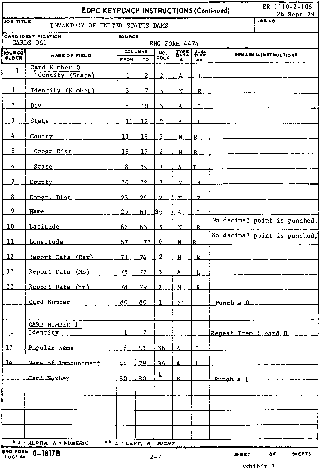

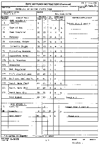
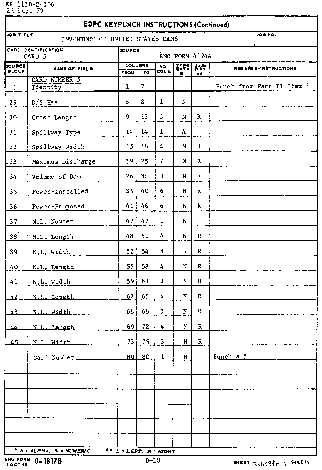

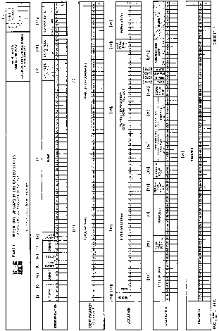

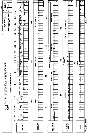
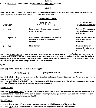
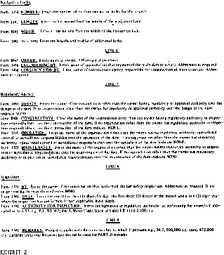
Appendix C to § 222.6 - Hydrologic and Hydraulic Assessment of Dams
1. Phase I inspections are not intended to provide detailed hydrologic and hydraulic analyses of dam and reservoir capabilities. However, when such analyses are available, they should be evaluated for reliability and completeness. If a project's ability to pass the appropriate flood (see Table 3, page D-12 of Recommended Guidelines) can be determined from available information of a brief study, such an assessment should be made. It should be noted that hydrologic and hydraulic analyses connected with the Phase I inspections should be based on approximate methods or systematized computer programs that take minimal effort. The Hydrologic Engineering Center (HEC) has developed a special computer program for hydrologic and hydraulic analyses to be used with the Phase I inspection program. Other Field Operating Agencies have developed similar computer programs or generalized procedures which are acceptable for use. All such efforts should be completed with minimum resources.
2. A finding that a dam will not safely pass the flood indicated in the Recommended Guidelines does not necessarily indicate that the dam should be classified as unsafe. The degree of inadequacy of the spillway to pass the appropriate flood and the probable adverse impacts of dam failure because of overtopping must be considered in making such classification. The following criteria have been selected which indicate when spillway capacity is so seriously inadequate that a project must be classified as unsafe. All of the following conditions must prevail before designating a dam unsafe:
a. There is high hazard to loss of life from large flows downstream of the dam.
b. Dam failure resulting from overtopping would significantly increase the hazard to loss of life downstream from the dam from that which would exist just before overtopping failure.
c. The spillway is not capable of passing one-half of the probable maximum flood without overtopping the dam and causing failure.
3. The above criteria are generally adequate for evaluating most non-Federal dams. However, in a few cases the increased hazard potential from overtopping and failure is so great as to result in catastrophic consequences. In such cases, the evaluation of condition 2c should utilize a flood more closely approximating the full probable maximum flood rather than one-half the flood. An example of such a situation would be a large dam immediately above a highly populated flood plain, with little likelihood of time for evacuation in the event of an emergency.
4. Conditions 2a and 2b require an approximation of housing location in relation to flooded areas. Resources available in Phase I inspections do not permit detailed surveys or time-consuming studies to develop such relationships. Therefore, rough estimates will generally be made from data obtained during the inspection and from readily available maps and drawings. Brief computer routings such as the HEC-1 dam break analysis, using available data, are recommended in marginal cases. The HEC-1, dam break version, is available on the Boeing Computer Services or may be obtained from the Hydrologic Engineering Center, Davis, California. Available resources do not permit detailed studies or investigations to establish the amount of overtopping that would cause a dam to fail, as designated in condition 2c. Professional judgment and available information will have to be used in these determinations. When detailed investigations and studies are required to make a reasonable judgment of the conditions which designate an unsafe dam, the inspection report should recommend that such studies be the responsibility of the dam owner.
5. During the inspection of a dam, consideration should be given to impacts on other dams located downstream from the project being inspected. When failure of a dam would be likely to cause failure of another dam(s) downstream, its designation as an unsafe dam could result in multiple impacts. Therefore, the information should be explicitly described in the inspection report. Such information may be vital to the priorities established by State Governors for dam improvements. Similarly, when the failure of an upstream dam (classified as unsafe) could cause failure of the dam being inspected, this information should be prominently displayed in the inspection report.
6. The criteria established in paragraph 2 for designating unsafe dams because of seriously inadequate spillways are considered reasonable and prudent. They provide a consistent bases for declaring unsafe dams and also serve as an effective compromise between the Recommended Guidelines and unduly low standards suggested by special interests and individuals unfamiliar with flood hazard potential.
7. The Hydrometeorological Branch (HMB) of the National Weather Service has reviewed some 500 experienced large storms in the United States. The purpose of the review was to ascertain the relative magnitude of experienced large storms to probable maximum precipitation (PMP) and their distribution throughout the country. Their review reveals that about 25 percent of the major storms have exceeded 50 percent of the probable maximum precipitation for one or more combinations of area and duration. In fact some storms have very closely approximated the PMP values. Exhibits C-1 thru C-5 indicate locations where experienced storms have exceeded 50 percent of the PMP.
8. There are several options to consider when selecting mitigation measures to avoid severe consequences of a dam failure from overtopping. The following measures may be required by a Governor when sufficient legal authority is available under State laws and a dam presents a serious threat to loss of life.
a. Remove the dam.
b. Increase the height of dam and/or spillway size to pass the probable maximum flood without overtopping the dam.
c. Purchase downstream land that would be adversely impacted by dam failure and restrict human occupancy.
d. Enhance the stability of the dam to permit overtopping by the probable maximum flood without failure.
e. Provide a highly reliable flood warning system (generally does not prevent damage but avoids loss of life).
Table 1 - Storms With Rainfall ≥150% of PMP, U.S. East of the 105th Meridian (for 10 mi2, 6 Hours; 200 mi2, 24 Hours and/or 1,000 mi2, 48 Hours)
| Storm date | Index No. | Corps assignment No. (if available) | Storm center | Latitude | Longitude | |
|---|---|---|---|---|---|---|
| Town | State | |||||
| July 26, 1819 | 1 | Catskill | NY | 42°12′ | 73°53′ | |
| Aug. 5, 1843 | 2 | Concordville | PA | 39°53′ | 75°32′ | |
| Sept. 10-13, 1878 | 3 | OR 9-19 | Jefferson | OH | 41°45′ | 80°46′ |
| Sept. 20-24, 1882 | 4 | NA 1-3 | Paterson | NJ | 40°55′ | 74°10′ |
| June 13-17, 1886 | 5 | LMV 4-27 | Alexandria | LA | 31°19′ | 92°33′ |
| June 27-July 11, 1899 | 6 | GM 3-4 | Turnersville | TX | 30°52′ | 96°32′ |
| Aug. 24-28, 1903 | 7 | MR 1-10 | Woodburn | IA | 40°57′ | 93°35′ |
| Oct. 7-11, 1903 | 8 | GL 4-9 | Paterson | NJ | 40°55′ | 74°10′ |
| July 18-23, 1909 | 9 | UMV 1-11B | Ironwood | MI | 46°27′ | 90°11′ |
| July 18-23, 1909 | 10 | UMV 1-11A | Beaulieu | MN | 47°21′ | 95°48′ |
| July 22-23, 1911 | 11 | Swede Home | NB | 40°22′ | 96°54′ | |
| July 19-24, 1912 | 12 | GL 2-29 | Merrill | WI | 45°11′ | 89°41′ |
| July 13-17, 1916 | 13 | SA 2-9 | Altapass | NC | 35°33′ | 82°01′ |
| Sept. 8-10, 1921 | 14 | GM 4-12 | Taylor | TX | 30°35′ | 97°18′ |
| Oct. 4-11, 1924 | 15 | SA 4-20 | New Smyrna | FL | 29°07′ | 80°55′ |
| Sept. 17-19, 1926 | 16 | MR 4-24 | Boyden | IA | 43°12′ | 96°00′ |
| Mar. 11-16, 1929 | 17 | UMV 2-20 | Elba | AL | 31°25′ | 86°04′ |
| June 30-July 2, 1932 | 18 | GM 5-1 | State Fish Hatchery | TX | 30°01′ | 99°07′ |
| Sept. 16-17, 1932 | 19 | Ripogenus Dam | ME | 45°53′ | 69°09′ | |
| July 22-27, 193 | 20 | LMV 2-26 | Logansport | LA | 31°58′ | 94°00′ |
| Apr. 3-4 1934 | 21 | SW 2-11 | Cheyenne | OK | 35°37′ | 99°40′ |
| May 30-31, 1935 | 22 | MR 3-28A | Cherry Creek | CO | 39°13′ | 104°32′ |
| May 31, 1935 | 23 | GM 5-20 | Woodward | TX | 29°20′ | 99°28′ |
| July 6-10, 1935 | 24 | NA 1-27 | Hector | NY | 42°30′ | 76°53′ |
| Sept. 2-6, 1935 | 25 | SA 1-26 | Easton | MD | 38°46′ | 76°01′ |
| Sept. 14-18, 1936 | 26 | GM 5-7 | Broome | TX | 31°47′ | 100°50′ |
| June 19-20, 1939 | 27 | Snyder | TX | 32°44′ | 100°55′ | |
| July 4-5, 1939 | 28 | Simpson | KY | 38°13′ | 83°22′ | |
| Aug. 19, 1939 | 29 | NA 2-3 | Manahawkin | NJ | 39°42′ | 74°16′ |
| June 3-4, 1940 | 30 | MR 4-5 | Grant Township | NB | 42°01′ | 96°53′ |
| Aug. 6-9, 1940 | 31 | LMV 4-24 | Miller Isl | LA | 29°45′ | 92°10′ |
| Aug. 10-17, 1940 | 32 | SA 5-19A | Keysville | VA | 37°03′ | 78°30′ |
| Sept. 1, 1940 | 33 | NA 2-4 | Ewan | NJ | 39°42′ | 75°12′ |
| Sept. 2-6, 1940 | 34 | SW 2-18 | Hallet | OK | 36°15′ | 96°36′ |
| Aug. 28-31, 1941 | 35 | UMV 1-22 | Haywood | WI | 46°00′ | 91°28′ |
| Oct. 17-22, 1941 | 36 | SA 5-6 | Trenton | FL | 29°48′ | 82°57′ |
| July 17-18, 1942 | 37 | OR 9-23 | Smethport | PA | 41°50′ | 78°25′ |
| Oct. 11-17, 1942 | 38 | SA 1-28A | Big Meadows | VA | 38°31′ | 78°26′ |
| May 6-12, 1943 | 39 | SW 2-20 | Warner | OK | 35°29′ | 95°18′ |
| May 12-20, 1943 | 40 | SW 2-21 | Nr. Mounds | OK | 35°52′ | 96°04′ |
| July 27-29, 1943 | 41 | GM 5-21 | Devers | TX | 30°02′ | 94°35′ |
| Aug. 4-5, 1943 | 42 | OR 3-30 | Nr. Glenville | WV | 38°56′ | 80°50′ |
| June 10-13, 1944 | 43 | MR 6-15 | Nr. Stanton | NB | 41°52′ | 97°03′ |
| Aug. 12-15, 1946 | 44 | MR 7-2A | Cole Camp | MO | 38°40′ | 93°13′ |
| Aug. 12-16, 1946 | 45 | MR 7-2B | Nr. Collinsville | IL | 38°40′ | 89°59′ |
| Sept. 26-27, 1946 | 46 | GM 5-24 | Nr. San Antonio | TX | 29°20′ | 98°29′ |
| June 23-24, 1948 | 47 | Nr. Del Rio | TX | 29°22′ | 100°37′ | |
| Sept. 3-7, 1950 | 48 | SA 5-8 | Yankeetown | FL | 29°03′ | 82°42′ |
| June 23-28, 1954 | 49 | SW 3-22 | Vic Pierce | TX | 30°22′ | 101°23′ |
| Aug. 17-20, 1955 | 50 | NA 2-22A | Westfield | MA | 42°07′ | 72°45′ |
| May 15-16, 1957 | 51 | Hennessey | OK | 36°02′ | 97°56′ | |
| June 14-15, 1957 | 52 | Nr. E. St. Louis | IL | 38°37′ | 90°24′ | |
| June 23-24, 1963 | 53 | David City | NB | 41°14′ | 97°05′ | |
| June 13-20, 1965 | 54 | Holly | CO | 37°43′ | 102°23′ | |
| June 24, 1966 | 55 | Glenullin | ND | 47°21′ | 101°19′ | |
| Aug. 12-13, 1966 | 56 | Nr. Greely | NB | 41°33′ | 98°32′ | |
| Sept. 19-24, 1967 | 57 | SW 3-24 | Falfurrias | TX | 27°16′ | 98°12′ |
| July 16-17, 1968 | 58 | Waterloo | IA | 42°30′ | 92°19′ | |
| July 4-5, 1969 | 59 | Nr. Wooster | OH | 40°50′ | 82°00′ | |
| Aug. 19-20, 1969 | 60 | NA 2-3 | Nr. Tyro | VA | 37°49′ | 79°00′ |
| June 9, 1972 | 61 | Rapid City | SD | 44°12′ | 103°31′ | |
| June 19-23, 1972 | 62 | Zerbe | PA | 40°37′ | 76°31′ | |
| July 21-22, 1972 | 63 | Nr. Cushing | MN | 46°10′ | 94°30′ | |
| Sept. 10-12, 1972 | 64 | Harlan | IA | 41°43′ | 95°15′ | |
| Oct. 10-11, 1973 | 65 | Enid | OK | 36°25′ | 97°52′ | |
Table 2 - Storms With Rainfall ≥50% of PMP, U.S. West of Continental Divide (for 10 mi2 6 Hours or 1,000 mi2 for One Duration Between 6 and 72 Hours)
| Storm date | Index No. | Storm center | Latitude | Longitude | Duration for 1,000 mi2 | |
|---|---|---|---|---|---|---|
| Town | State | |||||
| Aug. 11, 1890 | 1 | Palmetto | NV | 37°27′ | 117°42′ | |
| Aug. 12, 1891 | 2 | Campo | CA | 32°36′ | 116°28′ | |
| Aug. 28, 1898 | 3 | Ft. Mohave | AZ | 35°03′ | 114°36′ | |
| Oct. 4-6, 1911 | 4 | Gladstone | CO | 37°53′ | 107°39′ | |
| Dec. 29, 1913-Jan. 3, 1914 | 5 | CA | 39°55′ | 121°25′ | ||
| Feb. 17-22, 1914 | 6 | Colby Ranch | CA | 34°18′ | 118°07′ | |
| Feb. 20-25, 1917 | 7 | CA | 37°35′ | 119°36′ | ||
| Sept. 13, 1918 | 8 | Red Bluff | CA | 40°10′ | 122°14′ | |
| Feb. 26-Mar 4, 1938 | 9 | CA | 34°14′ | 117°11′ | ||
| Mar. 30-Apr. 2, 1931 | 10 | ID | 46°30′ | 114°50′ | 24 | |
| Feb. 26, 1932 | 11 | Big Four | WA | 48°05′ | 121°30′ | |
| Nov. 21, 1933 | 12 | Tatoosh Is | WA | 48°23′ | 124°44′ | |
| Jan. 20-25, 1935 | 13 | WA | 47°30′ | 123°30′ | 6 | |
| Jan. 20-25, 1935 | 14 | WA | 47°00′ | 122°00′ | 72 | |
| Feb. 4-8, 1937 | 15 | Cyamaca Dam | CA | 33°00′ | 116°35′ | |
| Dec. 9-12, 1937 | 16 | CA | 38°51′ | 122°43′ | ||
| Feb. 27-Mar. 4, 1938 | 17 | AZ | 34°57′ | 111°44′ | 12 | |
| Jan. 19-24, 1943 | 18 | CA | 37°35′ | 119°25′ | 18 | |
| Jan. 19-24, 1943 | 19 | Hoegee's Camp | CA | 34°13′ | 118°02′ | |
| Jan. 30-Feb. 3, 1945 | 20 | CA | 37°35′ | 119°30′ | ||
| Dec. 27, 1945 | 21 | Mt. Tamalpias | CA | 37°54′ | 122°34′ | |
| Nov. 13-21, 1950 | 22 | CA | 36°30′ | 118°30′ | 24 | |
| Aug. 25-30, 1951 | 23 | AZ | 34°07′ | 112°21′ | 72 | |
| July 19, 1955 | 24 | Chiatovich Flat | CA | 37°44′ | 118°15′ | |
| Aug. 16, 1958 | 25 | Morgan | UT | 41°03′ | 111°38′ | |
| Sept. 18, 1959 | 26 | Newton | CA | 40°22′ | 122°12′ | |
| June 7-8, 1964 | 27 | Nyack Ck | MT | 48°30′ | 113°38′ | 12 |
| Sept. 3-7, 1970 | 28 | UT | 37°38′ | 109°04′ | 6 | |
| Sept. 3-7, 1970 | 29 | AZ | 33°49′ | 110°56′ | 6 | |
| June 7, 1972 | 30 | Bakersfield | CA | 35°25′ | 119°03′ | |
| Dec. 9-12, 1937 | 31 | CA | 39°45′ | 121°30′ | 48 | |


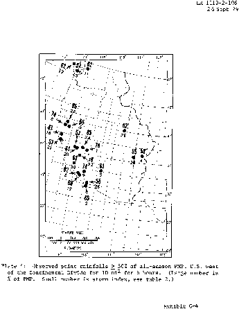
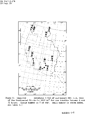
Appendix D to § 222.6 - Recommended Guidelines for Safety Inspection of Dams
Department of the Army - Office of the Chief of Engineers
Preface
The recommended guidelines for the safety inspection of dams were prepared to outline principal factors to be weighed in the determination of existing or potential hazards and to define the scope of activities to be undertaken in the safety inspection of dams. The establishment of rigid criteria or standards is not intended. Safety must be evaluated in the light of peculiarities and local conditions at a particular dam and in recognition of the many factors involved, some of which may not be precisely known. This can only be done by competent, experienced engineering judgment, which the guidelines are intended to supplement and not supplant. The guidelines are intended to be flexible, and the proper flexibility must be achieved through the employment of experienced engineering personnel.
Conditions found during the investigation which do not meet guideline recommendations should be assessed by the investigator as to their import from the standpoint of the involved degree of risk. Many deviations will not compromise project safety and the investigator is expected to identify them in this manner if that is the case. Others will involve various degrees of risk, the proper evaluation of which will afford a basis for priority of subsequent attention and possible remedial action.
The guidelines present procedures for investigating and evaluating existing conditions for the purpose of identifying deficiencies and hazardous conditions. The two phases of investigation outlined in the guidelines are expected to accomplish only this and do not encompass in scope the engineering which will be required to perform the design studies for corrective modification work.
It is recognized that some States may have established or will adopt inspection criteria incongruous in some respects with these guidelines. In such instances assessments of project safety should recognize the State's requirements as well as guideline recommendations.
The guidelines were developed with the help of several Federal agencies and many State agencies, professional engineering organizations, and private engineers. In reviewing two drafts of the guidelines they have contributed many helpful suggestions. Their contributions are deeply appreciated and have made it possible to evolve a document representing a consensus of the engineering fraternity. As experience is gained with use of the guidelines, suggestions for future revisions will be generated. All such suggestions should be directed to the Chief of Engineers, U.S. Army, DAEN-CWE-D, Washington, D.C. 20314.
Recommended Guidelines for Safety Inspection of Dams
Table of Contents
Preface
Chapter 1 - Introduction
Para.
1.1 Purpose.
1.2 Applicability.
1.3 Authority.
Chapter 2 - General Requirements
2.1 Classification of dams.
2.1.1 Size.
2.1.2 Hazard potential.
2.2 Selection of dams to be investigated.
2.3 Technical investigations.
2.4 Qualifications of investigators.
2.5 Reports.
Chapter 3 - Phase I Investigation
3.1 Purpose.
3.2 Scope.
3.3 Engineering data.
3.4 Field inspections.
3.5 Evaluation of hydraulic and hydrologic features.
3.5.1 Design data.
3.5.2 Experience data.
3.6 Evaluation of structural stability.
3.6.1 Design and construction data.
3.6.2 Operating records.
3.6.3 Post contruction changes.
3.6.4 Seismic stability.
Chapter 4 - Phase II Investigation
4.1 Purpose.
4.2 Scope.
4.3 Hydraulic and hydrologic analysis.
4.3.1 Maximum water surface based on SDF peak inflow.
4.3.1.1 Peak for 100-year flood.
4.3.1.2 Peak for PMF or fraction thereof.
4.3.2 Maximum water surface based on SDF hydrograph.
4.3.3 Acceptable procedures.
4.3.4 Freeboard allowances.
4.4 Stability investigations.
4.4.1 Foundation and material investigations.
4.4.2 Stability assessment.
4.4.2.1 Seismic stability.
4.4.2.2 Clay shale foundation.
4.4.3 Embankment dams.
4.4.3.1 Liquefaction.
4.4.3.2 Shear failure.
4.4.3.3 Loading conditions.
4.4.3.4 Safety factors.
4.4.3.5 Seepage failure.
4.4.3.6 Seepage analyses.
4.4.4 Concrete dams and appurtenant structures.
4.4.4.1 Requirements for stability.
4.4.4.2 Loads.
4.4.4.3 Stresses.
4.4.4.4 Overturning.
4.4.4.5 Sliding.
4.4.4.5.1 Sliding resistance.
4.4.4.5.2 Downstream resistance.
4.4.4.5.3 Safety factor.
Chapter 5 - Reports
5.1 General.
5.2 Preparation of report.
5.2.1 Phase I reports.
5.2.2 Phase II reports.
Tables
Table
1 Size classification.
2 Hazard potential classification.
3 Hydrologic evaluation guidelines.
4 Factors of safety (embankment dams).
Figures
Fig.
1 Seismic zone map of contiguous States.
2 Seismic zone map of California, Nevada and Arizona.
3 Seismic zone map of Alaska.
4 Seismic zone map of Hawaii.
5 Design envelope for Case I (Table 4).
6 Design envelope for Cases II and III (Table 4).
Appendixes
Appendix I to App. D - Engineering data
Appendix II to App. D - Inspection items
Appendix III to App. D - Pub. L. 92-367
Chapter 1 - Introduction
1.1. Purpose. This document provides recommended guidelines for the inspection and evaluation of dams to determine if they constitute hazards to human life or property.
1.2. Applicability. The procedures and guidelines outlined in this document apply to the inspection and evaluation of all dams as defined in the National Dam Inspection Act, Public Law 92-367. Included in this program are all artificial barriers together with appurtenant works which impound or divert water and which (1) are twenty-five feet or more in height or (2) have an impounding capacity of fifty acre-feet or more. Not included are barriers which are six feet or less in height, regardless of storage capacity, or barriers which have a storage capacity at maximum water storage elevation of fifteen acre-feet or less regardless of height.
1.3. Authority. The Dam Inspection Act, Public Law 92-367 (Appendix III), authorized the Secretary of the Army, through the Corps of Engineers, to initiate a program of safety inspection of dams throughout the United States. The Chief of Engineers issues these guidelines pursuant to that authority.
Chapter 2 - General Requirements
2.1. Classification of dams. Dams should be classified in accordance with size and hazard potential in order to formulate a priority basis for selecting dams to be included in the inspection program and also to provide compatibility between guideline requirements and involved risks. When possible the initial classifications should be based upon information listed in the National Inventory of Dams with respect to size, impoundment capacity and hazard potential. It may be necessary to reclassify dams when additional information becomes available.
2.1.1. Size. The classification for size based on the height of the dam and storage capacity should be in accordance with Table 1. The height of the dam is established with respect to the maximum storage potential measured from the natural bed of the stream or watercourse at the downstream toe of the barrier, or if it is not across a stream or watercourse, the height from the lowest elevation of the outside limit of the barrier, to the maximum water storage elevation. For the purpose of determining project size, the maximum storage elevation may be considered equal to the top of dam elevation. Size classification may be determined by either storage or height, whichever gives the larger size category.
Table 1 - Size Classification
| Category | Impoundment | |
|---|---|---|
| Storage (ac-ft) | Height (ft) | |
| Small | <1,000 and ≥50 | <40 and ≥25. |
| Intermediate | ≥1,000 and <50,000 | ≥40 and <100. |
| Large | ≥50,000 | ≥100. |
2.1.2. Hazard Potential. The classification for potential hazards should be in accordance with Table 2. The hazards pertain to potential loss of human life or property damage in the area downstream of the dam in event of failure or misoperation of the dam or appurtenant facilities. Dams conforming to criteria for the low hazard potential category generally will be located in rural or agricultural areas where failure may damage farm buildings, limited agricultural land, or township and country roads. Significant hazard potential category structures will be those located in predominantly rural or agricultural areas where failure may damage isolated homes, secondary highways or minor railroads or cause interruption of use or service of relatively important public utilities. Dams in the high hazard potential category will be those located where failure may cause serious damage to homes, extensive agricultural, industrial and commercial facilities, important public utilities, main highways, or railroads.
Table 2 - Hazard Potential Classification
| Category | Loss of life (extent of development) | Economic loss (extent of development) |
|---|---|---|
| Low | None expected (No permanent structures for human habitation) | Minimal (Undeveloped to occasional structures or agriculture). |
| Significant | Few (No urban developments and no more than a small number of inhabitable structures) | Appreciable (Notable agriculture, industry or structures). |
| High | More than few | Excessive (Extensive community, industry or agriculture). |
2.2. Selection of dams to be investigated. The selection of dams to be investigated should be based upon an assessment of existing developments in flood hazard areas. Those dams possessing a hazard potential classified high or significant as indicated in Table 2 should be given first and second priorities, respectively, in the inspection program. Inspection priorities within each category may be developed from a consideration of factors such as size classification and age of the dam, the population size in the downstream flood area, and potential developments anticipated in flood hazard areas.
2.3. Technical Investigations. A detailed, systematic, technical inspection and evaluation should be made of each dam selected for investigation in which the hydraulic and hydrologic capabilities, structural stability and operational adequacy of project features are analyzed and evaluated to determine if the dam constitutes a danger to human life or property. The investigation should vary in scope and completeness depending upon the availability and suitability of engineering data, the validity of design assumptions and analyses and the condition of the dam. The minimum investigation will be designated Phase I, and an in-depth investigation designated Phase II should be made where deemed necessary. Phase I investigations should consist of a visual inspection of the dam, abutments and critical appurtenant structures, and a review of readily available engineering data. It is not intended to perform costly explorations or analyses during Phase I. Phase II investigations should consist of all additional engineering investigations and analyses found necessary by results of the Phase I investigation.
2.4. Qualifications of investigators. The technical investigations should be conducted under the direction of licensed professional engineers experienced in the investigation, design, construction and operation of dams, applying the disciplines of hydrologic, hydraulic, soils and structural engineering and engineering geology. All field inspections should be conducted by qualified engineers, engineering geologists and other specialists, including experts on mechanical and electrical operation of gates and controls, knowledgeable in the investigation, design, construction and operation of dams.
Chapter 3 - Phase I Investigation
3.1. Purpose. The primary purpose of the Phase I investigation program is to identify expeditiously those dams which may pose hazards to human life or property.
3.2. Scope. The Phase I investigation will develop an assessment of the general condition with respect to safety of the project based upon available data and a visual inspection, determine any need for emergency measures and conclude if additional studies, investigation and analyses are necessary and warranted. A review will be made of pertinent existing and available engineering data relative to the design, construction and operation of the dam and appurtenant structures, including electrical and mechanical operating equipment and measurements from inspection and performance instruments and devices; and a detailed systematic visual inspection will be performed of those features relating to the stability and operational adequacy of the project. Based upon findings of the review of engineering data and the visual inspection, an evaluation will be made of the general condition of the dam, including where possible the assessment of the hydraulic and hydrologic capabilities and the structural stability.
3.3. Engineering data. To the extent feasible the engineering data listed in Appendix I relating to the design, construction and operation of the dam and appurtenant structures, should be collected from existing records and reviewed to aid in evaluating the adequacy of hydraulic and hydrologic capabilities and stability of the dam. Where the necessary engineering data are unavailable, inadequate or invalid, a listing should be made of those specific additional data deemed necessary by the engineer in charge of the investigation and included in the Phase I report.
3.4. Field inspections. The field inspection of the dam, appurtenant stuctures, reservoir area, and downstream channel in the vicinity of the dam should be conducted in a systematic manner to minimize the possibility of any significant feature being overlooked. A detailed checklist should be developed and followed for each dam inspected to document the examination of each significant structural and hydraulic feature including electrical and mechanical equipment for operation of the control facilities that affect the safety of the dam.
3.4.1. Particular attention should be given to detecting evidence of leakage, erosion, seepage, slope instability, undue settlement, displacement, tilting, cracking, deterioration, and improper functioning of drains and relief wells. The adequacy and quality of maintenance and operating procedures as they pertain to the safety of the dam and operation of the control facilities should also be assessed.
3.4.2. Photographs and drawings should be used freely to record conditions in order to minimize descriptions.
3.4.3. The field inspection should include appropriate features and items, including but not limited to those listed in Appendix II, which may influence the safety of the dam or indicate potential hazards to human life or property.
3.5. Evaluation of hydraulic and hydrologic Features.
3.5.1. Design data. Original hydraulic and hydrologic design assumptions obtained from the project records should be assessed to determine their acceptability in evaluating the safety of the dam. All constraints on water control such as blocked entrances, restrictions on operation of spillway and outlet gates, inadequate energy dissipators or restrictive channel conditions, significant reduction in reservoir capacity by sediment deposits and other factors should be considered in evaluating the validity of discharge ratings, storage capacity, hydrographs, routings and regulation plans. The discharge capacity and/or storage capacity should be capable of safely handling the recommended spillway design flood for the size and hazard potential classification of the dam as indicated in Table 3. The hydraulic and hydrologic determinations for design as obtained from project records will be acceptable if conventional techniques similar to the procedures outlined in paragraph 4.3. were used in obtaining the data. When the project design flood actually used exceeds the recommended spillway design flood, from Table 3, the project design flood will be acceptable in evaluating the safety of the dam.
Table 3 - Hydrologic Evaluation Guidelines
[Recommended spillway design floods]
| Hazard | Size | Spillway design flood (SDF)1 |
|---|---|---|
| Low | Small | 50 to 100-yr frequency. |
| Intermediate | 100-yr to 1⁄2 PMF. | |
| Large | 1⁄2 PMF to PMF. | |
| Significant | Small | 100-yr to 1⁄2 PMF. |
| Intermediate | 1⁄2 PMF to PMF. | |
| Large | PMF. | |
| High | Small | 1⁄2 PMF to PMF. |
| Intermediate | PMF. | |
| Large | PMF. |
1000-yr = 100-Year Exceedence Interval. The flood magnitude expected to be exceeded, on the average, of once in 100 years. It may also be expressed as an exceedence frequency with a one-percent chance of being exceeded in any given year.
PMF = Probable Maximum Flood. The flood that may be expected from the most severe combination of critical meteorologic and hydrologic conditions that are reasonably possible in the region. The PMF is derived from probable maximum precipitation (PMP), which information is generally available from the National Weather Service, NOAA. Most Federal agencies apply reduction factors to the PMP when appropriate. Reductions may be applied because rainfall isohyetals are unlikely to conform to the exact shape of the drainage basin and/or the storm is not likely to center exactly over the drainage basin. In some cases local topography will cause changes from the generalized PMP values, therefore it may be advisable to contact Federal construction agencies to obtain the prevailing practice in specific areas.
3.5.2. Experience data. In some cases where design data are lacking, an evaluation of overtopping potential may be based on watershed characteristics and rainfall and reservoir records. An estimate of the probable maximum flood may also be developed from a conservative, generalized comparison of the drainage area size and the magnitude of recently adopted probable maximum floods for damsites in comparable hydrologic regions. Where the review of such experience data indicates that the recommended spillway design flood would not cause overtopping additional hydraulic and hydrologic determinations will be unnecessary.
3.6. Evaluation of structural stability. The Phase I evaluations of structural adequacy of project features are expected to be based principally on existing conditions as revealed by the visual inspection, together with available design and construction information and records of performance. The objectives are to determine the existence of conditions which are hazardous, or which with time might develop into safety hazards, and to formulate recommendations pertaining to the need for any additional studies, investigations, or analyses. The results of this phase of the inspection must rely very substantially upon the experience and judgment of the inspecting engineer.
3.6.1. Design and construction data. The principal design assumptions and analyses obtained from the project records should be assessed. Original design and construction records should be used judiciously, recognizing the restricted applicability of such data as material strengths and permeabilities, geological factors and construction descriptions. Original stability studies and analyses should be acceptable if conventional techniques and procedures similar to those outlined in paragraph 4.4 were employed, provided that review of operational and performance data confirm that the original design assumptions were adequately conservative. The need for such analyses where either none exist or the originals are incomplete or unsatisfactory will be determined by the inspecting engineer based upon other factors such as condition of structures, prior maximum loadings and the hazard degree of the project. Design assumptions and analyses should include all applicable loads including earthquake and indicate the structure's capability to resist overturning, sliding and overstressing with adequate factors of safety. In general seepage and stability analyses comparable to the requirements of paragraph 4.4 should be on record for all dams in the high hazard category and large dams in the significant hazard category. This requirement for other dams will be subject to the opinion of the inspecting engineer.
3.6.2. Operating records. The performance of structures under prior maximum loading conditions should in some instances provide partial basis for stability evaluation. Satisfactory experience under loading conditions not expected to be exceeded in the future should generally be indicative of satisfactory stability, provided adverse changes in physical conditions have not occurred. Instrumentation observations of forces, pressures, loads, stresses, strains, displacements, deflections or other related conditions should also be utilized in the safety evaluation. Where such data indicate abnormal behavior, unsafe movement or deflections, or loadings which adversely affect the stability or functioning of the structure, prompt reporting of such circumstances is required without the delay for preparation of the official inspection report.
3.6.3. Post construction changes. Data should be collected on changes which have occurred since project construction that might influence the safety of the dam such as road cuts, quarries, mining and groundwater changes.
3.6.4. Seismic stability. An assessment should be made of the potential vulnerability of the dam to seismic events and a recommendation developed with regard to the need for additional seismic investigation. In general, projects located in Seismic Zones 0, 1 and 2 may be assumed to present no hazard from earthquake provided static stability conditions are satisfactory and conventional safety margins exist. Dams in Zones 3 and 4 should, as a minimum, have on record suitable analyses made by conventional equivalent static load methods. The seismic zones together with appropriate coefficients for use in such analyses are shown in Figures 1 through 4. Boundary lines are approximate and in the event of doubt about the proper zone, the higher zone should be used. All high hazard category dams in Zone 4 and high hazard dams of the hydraulic fill type in Zone 3 should have a stability assessment based upon knowledge of regional and local geology, engineering seismology, in situ properties of materials and appropriate dynamic analytical and testing procedures. The assessment should include the possibility of physical displacement of the structures due to movements along active faults. Departure from this general guidance should be made whenever in the judgment of the investigating engineer different seismic stability requirements are warranted because of local geological conditions or other reasons.
Chapter 4 - Phase II Investigation
4.1. Purpose. The Phase II investigation will be supplementary to Phase I and should be conducted when the results of the Phase I investigation indicate the need for additional in-depth studies, investigations or analyses.
4.2. Scope. The Phase II investigation should include all additional studies, investigations and analyses necessary to evaluate the safety of the dam. Included, as required, will be additional visual inspections, measurements, foundation exploration and testing, materials testing, hydraulic and hydrologic analysis and structural stability analyses.
4.3. Hydraulic and hydrologic analysis. Hydraulic and hydrologic capabilities should be determined using the following criteria and procedures. Depending on the project characteristics, either the spillway design flood peak inflow or the spillway design flood hydrograph should be the basis for determining the maximum water surface elevation and maximum outflow. If the operation or failure of upstream water control projects would have significant impact on peak flow or hydrograph analyses, the impact should be assessed.
4.3.1. Maximum water surface based on SDF peak inflow. When the total project discharge capability at maximum pool exceeds the peak inflow of the recommended SDF, and operational constraints would not prevent such a release at controlled projects, a reservoir routing is not required. The maximum discharge should be assumed equal to the peak inflow of the spillway design flood. Flood volume is not controlling in this situation and surcharge storage is either absent or is significant only to the extent that it provides the head necessary to develop the release capability required.
4.3.1.1. Peak for 100-year flood. When the 100-year flood is applicable under the provisions of Table 3 and data are available, the spillway design flood peak inflow may be determined by use of “A Uniform Technique for Determining Flood Frequencies,” Water Resources Council (WRC), Hydrology Committee, Bulletin 15, December 1967. Flow frequency information from regional analysis is generally preferred over single station results when available and appropriate. Rainfall-runoff techniques may be necessary when there are inadequate runoff data available to make a reasonable estimate of flow frequency.
4.3.1.2. Peak for PMF or fraction thereof. When either the Probable Maximum Flood peak or a fraction thereof is applicable under the provisions of Table 3, the unit hydrograph - infiltration loss technique is generally the most expeditious method of computing the spillway design flood peak for most projects. This technique is discussed in the following paragraph.
4.3.2. Maximum water surface based on SDF hydrograph. Both peak and volume are required in this analysis. Where surcharge storage is significant, or where there is insufficient discharge capability at maximum pool to pass the peak inflow of the SDF, considering all possible operational constraints, a flood hydrograph is required. When there are upstream hazard areas that would be imperiled by fast rising reservoirs levels, SDF hydrographs should be routed to ascertain available time for warning and escape. Determination of probable maximum precipitation or 100-year precipitation, which ever is applicable, and unit hydrographs or runoff models will be required, followed by the determination of the PMF or 100-year flood. Conservative loss rates (significantly reduced by antecedent rainfall conditions where appropriate) should be estimated for computing the rainfall excess to be utilized with unit hydrographs. Rainfall values are usually arranged with gradually ascending and descending rates with the maximum rate late in the storm. When applicable, conservatively high snowmelt runoff rates and appropriate releases from upstream projects should be assumed. The PMP may be obtained from National Weather Service (NWS) publications such as Hydrometeorological Report (HMR) 33. Special NWS publications for particular areas should be used when available. Rainfall for the 100-year frequency flood can be obtained from the NWS publication “Rainfall Frequency Atlas of the United States,” Technical Paper No. 40; Atlas 2, “Precipitation Frequency Atlas of Western United States;” or other NWS publications. The maximum water surface elevation and spillway design flood outflow are then determined by routing the inflow hydrograph through the reservoir surcharge storage, assuming a starting water surface at the bottom of surcharge storage, or lower when appropriate. For projects where the bottom of surcharge space is not distinct, or the flood control storage space (exclusive of surcharge) is appreciable, it may be appropriate to select starting water surface elevations below the top of the flood control storage for routings. Conservatively high starting levels should be estimated on the basis of hydrometeorological conditions reasonably characteristic for the region and flood release capability of the project. Necessary adjustment of reservoir storage capacity due to existing or future sediment or other encroachment may be approximated when accurate determination of deposition is not practicable.
4.3.3. Acceptable procedures. Techniques for performing hydraulic and hydrologic analyses are generally available from publications prepared by Federal agencies involved in water resources development or textbooks written by the academic community. Some of these procedures are rather sophisticated and require expensive computational equipment and large data banks. While results of such procedures are generally more reliable than simplified methods, their use is generally not warranted in studies connected with this program unless they can be performed quickly and inexpensively. There may be situations where the more complex techniques have to be employed to obtain reliable results; however, these cases will be exceptions rather than the rule. Whenever the acceptability of procedures is in question, the advice of competent experts should be sought. Such expertise is generally available in the Corps of Engineers, Bureau of Reclamation and Soil Conservation Service. Many other agencies, educational facilities and private consultants can also provide expert advice. Regardless of where such expertise is based, the qualification of those individuals offering to provide it should be carefully examined and evaluated.
4.3.4. Freeboard allowances. Guidelines on specific minimum freeboard allowances are not considered appropriate because of the many factors involved in such determinations. The investigator will have to assess the critical parameters for each project and develop its minimum requirement. Many projects are reasonably safe without freeboard allowance because they are designed for overtopping, or other factors minimize possible overtopping. Conversely, freeboard allowances of several feet may be necessary to provide a safe condition. Parameters that should be considered include the duration of high water levels in the reservoir during the design flood; the effective wind fetch and reservoir depth available to support wave generation; the probability of high wind speed occurring from a critical direction; the potential wave runup on the dam based on roughness and slope; and the ability of the dam to resist erosion from overtopping waves.
4.4 Stability investigations. The Phase II stability investigations should be compatible with the guidelines of this paragraph.
4.4.1 Foundation and material investigations. The scope of the foundation and materials investigation should be limited to obtaining the information required to analyze the structural stability and to investigate any suspected condition which would adversely affect the safety of the dam. Such investigations may include borings to obtain concrete, embankment, soil foundation, and bedrock samples; testing specimens from these samples to determine the strength and elastic parameters of the materials, including the soft seams, joints, fault gouge and expansive clays or other critical materials in the foundation; determining the character of the bedrock including joints, bedding planes, fractures, faults, voids and caverns, and other geological irregularities; and installing instruments for determining movements, strains, suspected excessive internal seepage pressures, seepage gradients and uplift forces. Special investigations may be necessary where suspect rock types such as limestone, gypsum, salt, basalt, claystone, shales or others are involved in foundations or abutments in order to determine the extent of cavities, piping or other deficiencies in the rock foundation. A concrete core drilling program should be undertaken only when the existence of significant structural cracks is suspected or the general qualitative condition of the concrete is in doubt. The tests of materials will be necessary only where such data are lacking or are outdated.
4.4.2. Stability assessment. Stability assessments should utilize in situ properties of the structure and its foundation and pertinent geologic information. Geologic information that should be considered includes groundwater and seepage conditions; lithology, stratigraphy, and geologic details disclosed by borings, “as-built” records, and geologic interpretation; maximum past overburden at site as deduced from geologic evidence; bedding, folding and faulting; joints and joint systems; weathering; slickensides, and field evidence relating to slides, faults, movements and earthquake activity. Foundations may present problems where they contain adversely oriented joints, slickensides or fissured material, faults, seams of soft materials, or weak layers. Such defects and excess pore water pressures may contribute to instability. Special tests may be necessary to determine physical properties of particular materials. The results of stability analyses afford a means of evaluating the structure's existing resistance to failure and also the effects of any proposed modifications. Results of stability analyses should be reviewed for compatibility with performance experience when possible.
4.4.2.1. Seismic stability. The inertial forces for use in the conventional equivalent static force method of analysis should be obtained by multiplying the weight by the seismic coefficient and should be applied as a horizontal force at the center of gravity of the section or element. The seismic coefficients suggested for use with such analyses are listed in Figures 1 through 4. Seismic stability investigations for all high hazard category dams located in Seismic Zone 4 and high hazard dams of the hydraulic fill type in Zone 3 should include suitable dynamic procedures and analyses. Dynamic analyses for other dams and higher seismic coefficients are appropriate if in the judgment of the investigating engineer they are warranted because of proximity to active faults or other reasons. Seismic stability investigations should utilize “state-of-the-art” procedures involving seismological and geological studies to establish earthquake parameters for use in dynamic stability analyses and, where appropriate, the dynamic testing of materials. Stability analyses may be based upon either time-history or response spectra techniques. The results of dynamic analyses should be assessed on the basis of whether or not the dam would have sufficient residual integrity to retain the reservoir during and after the greatest or most adverse earthquake which might occur near the project location.
4.4.2.2. Clay shale foundation. Clay shale is a highly overconsolidated sedimentary rock comprised predominantly of clay minerals, with little or no cementation. Foundations of clay shales require special measures in stability investigations. Clay shales, particularly those containing montmorillonite, may be highly susceptible to expansion and consequent loss of strength upon unloading. The shear strength and the resistance to deformation of clay shales may be quite low and high pore water pressures may develop under increase in load. The presence of slickensides in clay shales is usually an indication of low shear strength. Prediction of field behavior of clay shales should not be based solely on results of conventional laboratory tests since they may be misleading. The use of peak shear strengths for clay shales in stability analyses may be unconservative because of nonuniform stress distribution and possible progressive failures. Thus the available shear resistance may be less than if the peak shear strength were mobilized simultaneously along the entire failure surface. In such cases, either greater safety factors or residual shear strength should be used.
4.4.3. Embankment dams.
4.4.3.1. Liquefaction. The phenomenon of liquefaction of loose, saturated sands and silts may occur when such materials are subjected to shear deformation or earthquake shocks. The possibility of liquefaction must presently be evaluated on the basis of empirical knowledge supplemented by special laboratory tests and engineering judgment. The possiblitity of liquefaction in sands diminishes as the relative density increases above approximately 70 percent. Hydraulic fill dams in Seismic Zones 3 and 4 should receive particular attention since such dams are susceptible to liquefaction under earthquake shocks.
4.4.3.2. Shear failure. Shear failure is one in which a portion of an embankment or of an embankment and foundation moves by sliding or rotating relative to the remainder of the mass. It is conventionally represented as occurring along a surface and is so assumed in stability analyses, although shearing may occur in a zone of substantial thickness. The circular arc or the sliding wedge method of analyzing stability, as pertinent, should be used. The circular arc method is generally applicable to essentially homogeneous embankments and to soil foundations consisting of thick deposits of fine-grained soil containing no layers significantly weaker than other strata in the foundation. The wedge method is generally applicable to rockfill dams and to earth dams on foundations containing weak layers. Other methods of analysis such as those employing complex shear surfaces may be appropriate depending on the soil and rock in the dam and foundation. Such methods should be in reputable usage in the engineering profession.
4.4.3.3. Loading conditions. The loading conditions for which the embankment structures should be investigated are (I) Sudden drawdown from spillway crest elevation or top of gates, (II) Partial pool, (III) Steady state seepage from spillway crest elevation or top of gate elevation, and (IV) Earthquake. Cases I and II apply to upstream slopes only; slopes; and Case IV applies to both upstream and downstream Case III applies to downstream slopes. A summary of suggested strengths and safety factors are shown in Table 4.
Table 4 - Factors of Safety1
| Case and loading condition | Factor of safety | Shear2 strength | Remarks |
|---|---|---|---|
| I Sudden drawdown from spillway crest or top of gates to minimum drawdown elevation | 3 1.2 | Minimum composite of R and S shear strengths. See Figure 5 | Within the drawdown zone submerged unit weights of materials are used for computing forces resisting sliding and saturated unit weights are used for computing forces contributing to sliding. |
| II Partial pool with assumed horizontal steady seepage saturation | 1.5 | R + S/2 for R<S
S for R>S |
Composite intermediate envelope of R and
S shear strengths. See Figure 6. |
| III Steady seepage from spillway crest or top of gates with Kh/Kv = 9 assumed4 | 1.5 | Same as Case II | |
| IV Earthquake (Cases II and III with seismic loading) | 1.0 | (5 ) | See Figures 1 through 4 for Seismic Coefficients. |
4.4.3.4. Safety factors. Safety factors for embankment dam stability studies should be based on the ratio of available shear strength to developed shear strength, SD:

Where:
C = Cohesion
φ = Angle of internal friction
σ = Normal stress
The factors of safety listed in Table 4 are recommended as minimum acceptable. Final accepted factors of safety should depend upon the degree of confidence the investigating engineer has in the engineering data available to him. The consequences of a failure with respect to human life and property damage are important considerations in establishing factors of safety for specific investigations.
4.4.3.5. Seepage failure. A critical uncontrolled underseepage or through seepage condition that develops during a rising pool can quickly reduce a structure which was stable under previous conditions, to a total structural failure. The visually confirmed seepage conditions to be avoided are (1) the exit of the phreatic surface on the downstream slope of the dam and (2) development of hydrostatic heads sufficient to create in the area downstream of the dam sand boils that erode materials by the phenomenon known as “piping” and (3) localized concentrations of seepage along conduits or through pervious zones. The dams most susceptible to seepage problems are those built of or on pervious materials of uniform fine particle size, with no provisions for an internal drainage zone and/or no underseepage controls.
4.4.3.6. Seepage analyses. Review and modifications to original seepage design analyses should consider conditions observed in the field inspection and piezometer instrumentation. A seepage analysis should consider the permeability ratios resulting from natural deposition and from compaction placement of materials with appropriate variation between horizontal and vertical permeability. An underseepage analysis of the embankment should provide a critical gradient factor of safety for the maximum head condition of not less than 1.5 in the area downstream of the embankment.

Where:
ic = Critical gradient
i = Design gradient
H = Uplift head at downstream toe of dam measured above tailwater
Hc = The critical uplift
Db = The thickness of the top impervious blanket at the downstream toe of the dam
γm = The estimated saturated unit weight of the material in the top impervious blanket
γw = The unit weight of water
Where a factor of safety less than 1.5 is obtained the provision of an underseepage control system is indicated. The factor of safety of 1.5 is a recommended minimum and may be adjusted by the responsible engineer based on the competence of the engineering data.
4.4.4. Concrete dams and appurtenant structures.
4.4.4.1. Requirements for stability. Concrete dams and structures appurtenant to embankment dams should be capable of resisting overturning, sliding and overstressing with adequate factors of safety for normal and maximum loading conditions.
4.4.4.2. Loads. Loadings to be considered in stability analyses include the water load on the upstream face of the dam; the weight of the structure; internal hydrostatic pressures (uplift) within the body of the dam, at the base of the dam and within the foundation; earth and silt loads; ice pressure, seismic and thermal loads, and other loads as applicable. Where tailwater or backwater exists on the downstream side of the structure it should be considered, and assumed uplift pressures should be compatible with drainage provisions and uplift measurements if available. Where applicable, ice pressure should be applied to the contact surface of the structure of normal pool elevation. A unit pressure of not more than 5,000 pounds per square foot should be used. Normally, ice thickness should not be assumed greater than two feet. Earthquake forces should consist of the inertial forces due to the horizontal acceleration of the dam itself and hydrodynamic forces resulting from the reaction of the reservoir water against the structure. Dynamic water pressures for use in a conventional methods of analysis may be computed by means of the “Westergaard Formula” using the parabolic approximation (H.M. Westergaard, “Water Pressures on Dams During Earthquakes,” Trans., ASCE, Vol 98, 1933, pages 418-433), or similar method.
4.4.4.3. Stresses. The analysis of concrete stresses should be based on in situ properties of the concrete and foundation. Computed maximum compressive stresses for normal operating conditions in the order of 1⁄3 or less of in situ strengths should be satisfactory. Tensile stresses in unreinforced concrete should be acceptable only in locations where cracks will not adversely affect the overall performance and stability of the structure. Foundation stresses should be such as to provide adequate safety against failure of the foundation material under all loading conditions.
4.4.4.4. Overturning. A gravity structure should be capable of resisting all overturning forces. It can be considered safe against overturning if the resultant of all combinations of horizontal and vertical forces, excluding earthquake forces, acting above any horizontal plane through the structure or at its base is located within the middle third of the section. When earthquake is included the resultant should fall within the limits of the plane or base, and foundation pressures must be acceptable. When these requirements for location of the resultant are not satisfied the investigating engineer should assess the importance to stability of the deviations.
4.4.4.5. Sliding. Sliding of concrete gravity structures and of abutment and foundation rock masses for all types of concrete dams should be evaluated by the shear-friction resistance concept. The available sliding resistance is compared with the driving force which tends to induce sliding to arrive at a sliding stability safety factor. The investigation should be made along all potential sliding paths. The critical path is that plane or combination of planes which offers the least resistance.
4.4.4.5.1. Sliding resistance. Sliding resistance is a function of the unit shearing strength at no normal load (cohesion) and the angle of friction on a potential failure surface. It is determined by computing the maximum horizontal driving force which could be resisted along the sliding path under investigation. The following general formula is obtained from the principles of statics and may be derived by resolving forces parallel and perpendicular to the sliding plane:

Where:
RR = Sliding Resistance (maximum horizontal driving force which can be resisted by the critical path)
φ = Angle of internal friction of foundation material or, where applicable, angle of sliding friction
V = Summation of vertical forces (including uplift)
c = Unit shearing strength at zero normal loading along potential failure plane
A = Area of potential failure plane developing unit shear strength “c”
α = Angle between inclined plane and horizontal (positive for uphill sliding)
For sliding downhill the angle α is negative and Equation (1) becomes:

When the plane of investigation is horizontal, and the angle α is zero and Equation (1) reduced to the following:

4.4.4.5.2. Downstream esistance. When the base of a concrete structure is embedded in rock or the potential failure plane lies below the base, the passive resistance of the downstream layer of rock may sometimes be utilized for sliding resistance. Rock that may be subjected to high velocity water scouring should not be used. The magnitude of the downstream resistance is the lesser of (a) the shearing resistance along the continuation of the potential sliding plane until it daylights or (b) the resistance available from the downstream rock wedge along an inclined plane. The theoretical resistance offered by the passive wedge can be computed by a formula equivalent to formula (3):

Where:
Pp = Passive resistance of rock wedge
W = Weight (buoyant weight if applicable) of downstream rock wedge above inclined plane of resistance, plus any superimposed loads
φ = Angle of internal friction or, if applicable, angle of sliding friction
α = Angle between inclined failure plane and horizontal
c = Unit shearing strength at zero normal load along failure plane
A = Area of inclined plane of resistance
When considering cross-bed shear through a relatively shallow, competent rock strut, without adverse jointing or faulting, W and α may be taken at zero and 45°, respectively, and an estimate of passive wedge resistance per unit width obtained by the following equation:

Where:
D = Thickness of the rock strut
4.4.4.5.3. Safety factor. The shear-friction safety factor is obtained by dividing the resistance RR by H, the summation of horizontal service loads to be applied to the structure:

When the downstream passive wedge contributes to the sliding resistance, the shear friction safety factor formula becomes:

The above direct superimposition of passive wedge resistance is valid only if shearing rigidities of the foundation components are similar. Also, the compressive strength and buckling resistance of the downstream rock layer must be sufficient to develop the wedge resistance. For example, a foundation with closely spaced, near horizontal, relatively weak seams might not contain sufficient buckling strength to develop the magnitude of wedge resistance computed from the cross-bed shear strength. In this case wedge resistance should not be assumed without resorting to special treatment (such as installing foundation anchors). Computed sliding safety factors approximating 3 or more for all loading conditions without earthquake, and 1.5 including earthquake, should indicate satisfactory stability, depending upon the reliability of the strength parameters used in the analyses. In some cases when the results of comprehensive foundation studies are available, smaller safety factors may be acceptable. The selection of shear strength parameters should be fully substantiated. The bases for any assumptions; the results of applicable testing, studies and investigations; and all pre-existing, pertinent data should be reported and evaluated.
Chapter 5 - Reports
5.1. General. This chapter outlines the procedures for reporting the results of the technical investigations. Hazardous conditions should be reported immediately upon detection to the owner of the dam, the Governor of the State in which the dam is located and the appropriate regulatory agency without delay for preparation of the formal report.
5.2. Preparation of report. A formal report should be prepared for each dam investigated for submission to the regulatory agency and the owner of the dam. Each report should contain the information indicated in the following paragraphs. The signature and registration identification of the professional engineer who directed the investigation and who was responsible for evaluation of the dam should be included in the report.
5.2.1. Phase I reports. Phase I reports should contain the following information:
5.2.1.1. Description of dam including regional vicinity map showing location and plans, elevations and sections showing the essential project features and the size and hazard potential classifications.
5.2.1.2. Summary of existing engineering data, including geologic maps and information.
5.2.1.3. Results of the visual inspection of each project feature including photographs and drawings to minimize descriptions.
5.2.1.4. Evaluation of operational adequacy of the reservoir regulation plan and maintenance of the dam and operating facilities and features that pertain to the safety of the dam.
5.2.1.5. Description of any warning system in effect.
5.2.1.6. Evaluation of the hydraulic and hydrologic assumptions and structural stability.
5.2.1.7. An assessment of the general condition of the dam with respect to safety based upon the findings of the visual inspection and review of engineering data. Where data on the original design indicate significant departure from or non-conformance with guidelines contained herein, the engineer-in-charge of the investigation will give his opinion of the significance, with regard to safety, of such factors. Any additional studies, investigations and analyses considered essential to assessment of the safety of the dam should be listed, together with an opinion about the urgency of such additional work.
5.2.1.8. Indicate alternative possible remedial measures or revisions in operating and maintenance procedures which may (subject to further evaluation) correct deficiencies and hazardous conditions found during the investigation.
5.2.2. Phase II reports. Phase II reports should describe the detailed investigations and should supplement Phase I reports. They should contain the following information:
5.2.2.1. Summary of additional engineering data obtained to determine the hydraulic and hydrologic capabilities and/or structural stability.
5.2.2.2. Results of all additional studies, investigations, and analyses performed.
5.2.2.3. Technical assessment of dam safety including deficiences and hazardous conditions found to exist.
5.2.2.4. Indicate alternative possible remedial measures or revision in maintenance and operating procedures which may (subject to further evaluation) correct deficiencies and hazardous conditions found during the investigation.
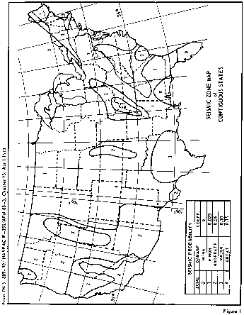


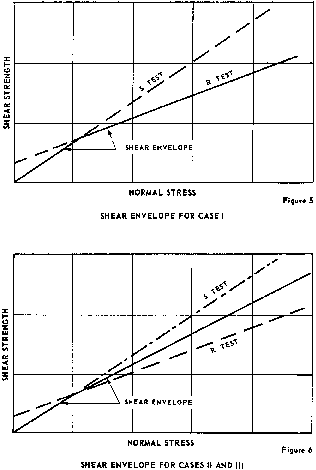
Appendix I to App. D to § 222.6 - Engineering Data
This appendix lists engineering data which should be collected from project records and, to the extent available, included in the Phase I investigation report. The list is intended to serve as a checklist and not to establish rigid data requirements. Such a compilation should also facilitate future inspections and investigations. Only data readily available will be included in Phase I reports, but data lacking and deemed necessary for an adequate safety evaluation should be identified.
1. General Project Data.
a. Regional Vicinity Map showing the location of the dam, the upstream drainage area and the downstream area subject to potential damage due to failure of the dam and misoperation or failure of the operating equipment.
b. As-Built Drawings indicating plans, elevations and sections of the dam and appurtenant structures including the details of the discharge facilities such as outlet works, limited service and emergency spillways, flashboards, fuse plugs and operating equipment.
2. Hydrologic and Hydraulic Data including the following:
a. Drainage area and basin runoff characteristics (indicating pending changes).
b. Elevation of top of conservation pool or normal upper retention water surface elevation, as applicable (base level of any flood impoundment).
c. Storage capacity including dead or inactive storage, corresponding to top of conservation or normal upper retention level (cumulative, excluding flood control and surcharge storage).
d. Elevation of the top of flood control pool.
e. Storage capacity of flood control zone (incremental).
f. Elevation of maximum design pool (corresponding to top of surcharge storage or spillway design flood).
g. Storage capacity of surcharge zone (incremental, above top of flood control pool or, above normal upper retention level if flood control space not provided).
h. Height of freeboard (distance between maximum design flood water surface and top of dam).
i. Elevation of top of dam (lowest point of embankment or non-overflow structure).
j. Elevation of crest, type, width, crest length and location of spillways (number, size and type of gates if controlled).
k. Type, location, entrance and exit inverts of outlet works and emergency drawdown facilities (number, size and shape of conduits and gates, including penstocks and sluices).
l. Location, crest elevation, description of invert and abutments (concrete, rock, grass, earth) and length of limited service and emergency spillways.
m. Location and dscription of flashboards and fuse plugs, including hydraulic head (pool elevation) and other conditions required for breaching, along with the assumed results of breaching.
n. Location and top elevation of dikes and floodwalls (overflow and non-overflow) affected by reservoir. Include information on low reaches of reservoir rim.
o. Type, location, observations and records of hydrometeorological gages appurtenant to the project.
p. Maximum non-damaging discharge, or negligible damage rate, at potential damage locations downstream.
3. Foundation Data and Geological Features including logs of borings, geological maps, profiles and cross sections, and reports of foundation treatment.
4. Properties of Embankments and Foundation Materials including results of laboratory tests, field permeability tests, construction control tests, and assumed design properties for materials.
5. Concrete Properties including the source and type of aggregate, cement used, mix design data and the results of testing during construction.
6. Electrical and Mechanical Equipment type and rating of normal and emergency power supplies, hoists, cranes, valves and valve operator, control and alarm systems and other electrical and mechanical equipment and systems that could affect the safe operation of the dam.
7. Construction History including diversion scheme, construction sequence, pertinent construction problems, alterations, modifications and maintenance repairs.
8. Water Control Plan including regulation plan under normal conditions and during flood events or other emergency conditions. The availability of dam tenders, means of communication between dam tenders and authority supervising water control, and method of gate operation (manual, automatic, or remote control) should be included. Flood warning systems should be described in sufficient detail to enable assessment of their reduction in the flood hazard potential.
9. Operation Record.
a. Summary of past major flood events including any experiences that presented a serious threat to the safety of the project or to human life or property. The critical project feature, date and duration of event, causative factor, peak inflow and outflow, maximum elevation of water surface, wind and wave factors if significant, issuance of alert or evacuation warnings and adequacy of project feature involved should be included in the summary of past experience of serious threat to the safety of the project.
b. Records of performance observations including instrumentation records.
c. List of any known deficiencies that pose a threat to the safety of the dam or to human life or property.
d. History of previous failures or deficiencies and pending remedial measures for correcting known deficiencies and the schedule for accomplishing remedial measures should be indicated.
10. Earthquake History including a summary of the seismic data of significant recorded earthquakes in the vicinity of the dam and information on major damage in the vicinity of the dam from both recorded and unrecorded earthquakes. Regional geologic maps and other documents showing fault locations should be collected.
11. Inspection History including the results of the last safety inspection, the organization that performed the inspection, the date inspection performed and the authority for conducting the inspection.
12. Principal Design Assumptions and Analyses.
a. Hydrologic and Hydraulic Determinations.
(1) Quantity, time and area distribution, and reference source of depth-area-duration data of spillway design storm precipitation (point precipitation if applicable).
(2) Maximum design flood inflow hydrograph including loss rates (initial and average for design flood conditions) and time of runoff concentration of reservior watershed (peak inflow only when applicable).
(3) Maximum design flood outflow hydrograph (maximum outflow only when applicable).
(4) Discharge-frequency relationship, preferably at damsite, including estimated frequency of spillway design flood for small dams, when appropriate.
(5) Reservior area and storage capacity versus water surface elevation (table or curves).
(6) Rating curves (free flow and partial gate openings) for all discharge facilities contributing to the maximum design flood outflow hydrograph. Also a composite-rating of all contributing facilities, if appropriate.
(7) Tailwater rating curve immediately below damsite including elevation corresponding to maximum design flood discharge and approximate nondamaging channel capacity.
(8) Hydrologic map of watershed above damsite including reservior area, watercourse, elevation contours, and principal stream-flow and precipitation gaging stations.
b. Stability and Stress Analysis of the dam, spillway and appurtenant structures and features including the assumed properties of materials and all pertinent applied loads.
c. Seepage and Settlement Analyses. The determination of distribution, direction and magnitude of seepage forces and the design and construction measures for their control. Settlement estimates and steps adopted to compensate for total settlement and to minimize differential settlements.
Appendix II to App. D to § 222.6 - Inspection Items
This appendix provides guidance for performing field inspections and may serve as the basis for developing a detailed checklist for each dam.
1. Concrete Structures in General.
a. Concrete Surfaces. The condition of the concrete surfaces should be examined to evaluate the deterioration and continuing serviceability of the concrete. Descriptions of concrete conditions should conform with the appendix to “Guide for Making a Condition Survey of Concrete in Service,” American Concrete Institute (ACI) Journal, Proceedings Vol. 65, No. 11, November 1968, page 905-918.
b. Structural Cracking. Concrete structures should be examined for structural cracking resulting from overstress due to applied loads, shrinkage and temperature effects or differential movements.
c. Movement - Horizontal and Vertical Alignment. Concrete structures should be examined for evidence of any abnormal settlements, heaving, deflections, or lateral movements.
d. Junctions. The conditions at the junctions of the structure with abutments or embankments should be determined.
e. Drains - Foundation, Joint, Face. All drains should be examined to determine that they are capable of performing their design function.
f. Water Passages. All water passages and other concrete surfaces subject to running water should be examined for erosion, cavitation, obstructions, leakage or significant structural cracks.
g. Seepage or Leakage. The faces, abutments and toes of the concrete structures should be examined for evidence of seepage or abnormal leakage, and records of flow of downstream springs reviewed for variation with reservoir pool level. The sources of seepage should be determined if possible.
h. Monolith Joints - Construction Joints. All monolith and construction joints should be examined to determine the condition of the joint and filler material, any movement of joints, or any indication of distress or leakage.
i. Foundation. Foundation should be examined for damage or possible undermining of the downstream toe.
j. Abutments. The abutments should be examined for sign of instability or excessive weathering.
2. Embankment Structures.
a. Settlement. The embankments and downstream toe areas should be examined for any evidence of localized or overall settlement, depressions or sink holes.
b. Slope Stability. Embankment slopes should be examined for irregularities in alignment and variances from smooth uniform slopes, unusual changes from original crest alignment and elevation, evidence of movement at or beyond the toe, and surface cracks which indicate movement.
c. Seepage. The downstream face of abutments, embankment slopes and toes, embankment - structure contacts, and the downstream valley areas should be examined for evidence of existing or past seepage. The sources of seepage should be investigated to determine cause and potential severity to dam safety under all operating conditions. The presence of animal burrows and tree growth on slopes which might cause detrimental seepage should be examined.
d. Drainage Systems. All drainage systems should be examined to determine whether the systems can freely pass discharge and that the discharge water is not carrying embankment or foundation material. Systems used to monitor drainage should be examined to assure they are operational and functioning properly.
e. Slope Protection. The slope protection should be examined for erosion-formed gullies and wave-formed notches and benches that have reduced the embankment cross-section or exposed less wave resistant materials. The adequacy of slope protection against waves, currents, and surface runoff that may occur at the site should be evaluated. The condition of vegetative cover should be evaluated where pertinent.
3. Spillway Structures. Examination should be made of the structures and features including bulkheads, flashboards, and fuse plugs of all service and auxiliary spillways which serve as principal or emergency spillways for any condition which may impose operational constraints on the functioning of the spillway.
a. Control Gates and Operating Machinery. The structural members, connections, hoists, cables and operating machinery and the adequacy of normal and emergency power supplies should be examined and tested to determine the structural integrity and verify the operational adequacy of the equipment. Where cranes are intended to be used for handling gates and bulkheads, the availability, capacity and condition of the cranes and lifting beams should be investigated. Operation of control systems and protective and alarm devices such as limit switches, sump high water alarms and drainage pumps should be investigated.
b. Unlined Saddle Spillways. Unlined saddle spillways should be examined for evidence of erosion and any conditions which may impose constraints on the functioning of the spillway. The ability of the spillway to resist erosion due to operation and the potential hazard to the safety of the dam from such operation should be determined.
c. Approach and Outlet Channels. The approach and outlet channels should be examined for any conditions which may impose constraints on the functioning of the spillway and present a potential hazard to the safety of the dam.
d. Stilling Basin (Energy Dissipators). Stilling basins including baffles, flip buckets or other energy dissipators should be examined for any conditions which may pose constraints on the ability of the stilling basin to prevent downstream scour or erosion which may create or present a potential hazard to the safety of the dam. The existing condition of the channel downstream of the stilling basin should be determined.
4. Outlet Works. The outlet works examination should include all structures and features designed to release reservoir water below the spillway crest through or around the dam.
a. Intake Structure. The structure and all features should be examined for any conditions which may impose operational constraints on the outlet works. Entrances to intake structure should be examined for conditions such as silt or debris accumulation which may reduce the discharge capabilities of the outlet works.
b. Operating and Emergency Control Gates. The structural members, connections, guides, hoists, cables and operating machinery including the adequacy of normal and emergency power supplies should be examined and tested to determine the structural integrity and verify the operational adequacy of the operating and emergency gates, valves, bulkheads, and other equipment.
c. Conduits, Sluices, Water Passages, Etc. The interior surfaces of conduits should be examined for erosion, corrosion, cavitation, cracks, joint separation and leakage at cracks or joints.
d. Stilling Basin (Energy Dissipator). The stilling basin or other energy dissipator should be examined for conditions which may impose any constraints on the ability of the stilling basin to prevent downstream scour or erosion which may create or present a potential hazard to the safety of the dam. The existing condition of the channel downstream of the stilling basin should be determined by soundings.
e. Approach and Outlet Channels. The approach and outlet channels should be examined for any conditions which may impose constraints on the functioning of the discharge facilities of the outlet works, or present a hazard to the safety of the dam.
f. Drawdown Facilities. Facilities provided for drawdown of the reservoir to avert impending failure of the dam or to facilitate repairs in the event of stability or foundation problems should be examined for any conditions which may impose constraints on their functioning as planned.
5. Safety and Performance Instrumentation. Instruments which have been installed to measure behavior of the structures should be examined for proper functioning. The available records and readings of installed instruments should be reviewed to detect any unusual performance of the instruments or evidence of unusual performance or distress of the structure. The adequacy of the installed instrumentation to measure the performance and safety of the dam should be determined.
a. Headwater and Tailwater Gages. The existing records of the headwater and tailwater gages should be examined to determine the relationship between other instrumentation measurements such as stream flow, uplift pressures, alignment, and drainage system discharge with the upper and lower water surface elevations.
b. Horizontal and Vertical Alignment Instrumentation (Concrete Structures). The existing records of alignment and elevation surveys and measurements from inclinometers, inverted plumb bobs, gage points across cracks and joints, or other devices should be examined to determine any change from the original position of the structures.
c. Horizontal and Vertical Movement, Consolidation, and Pore-Water Pressure Instrumentation (Embankment Structures). The existing records of measurements from settlement plates or gages, surface reference marks, slope indicators and other devices should be examined to determine the movement history of the embankment. Existing piezometer measurements should be examined to determine if the pore-water pressures in the embankment and foundation would under given conditions impair the safety of the dam.
d. Uplift Instrumentation. The existing records of uplift measurements should be examined to determine if the uplift pressures for the maximum pool would impair the safety of the dam.
e. Drainage System Instrumentation. The existing records of measurements of the drainage system flow should be examined to establish the normal relationship between pool elevations and discharge quantities and any changes that have occurred in this relationship during the history of the project.
f. Seismic Instrumentation. The existing records of seismic instrumentation should be examined to determine the seismic activity in the area and the response of the structures of past earthquakes.
6. Reservoir. The following features of the reservoir should be examined to determine to what extent the water impounded by the dam would constitute a danger to the safety of the dam or a hazard to human life or property.
a. Shore line. The land forms around the reservoir should be examined for indications of major active or inactive landslide areas and to determine susceptibility of bedrock stratigraphy to massive landslides of sufficient magnitude to significantly reduce reservoir capacity or create waves that might overtop the dam.
b. Sedimentation. The reservoir and drainage area should be examined for excessive sedimentation or recent developments in the drainage basin which could cause a sudden increase in sediment load thereby reducing the reservoir capacity with attendant increase in maximum outflow and maximum pool elevation.
c. Potential Upstream Hazard Areas. The reservoir area should be examined for features subject to potential backwater flooding resulting in loss of human life or property at reservoir levels up to the maximum water storage capacity including any surcharge storage.
d. Watershed Runoff Potential. The drainage basin should be examined for any extensive alterations to the surface of the drainage basin such as changed agriculture practices, timber clearing, railroad or highway construction or real estate developments that might extensively affect the runoff characteristics. Upstream projects that could have impact on the safety of the dam should be identified.
7. Downstream Channel. The channel immediately downstream of the dam should be examined for conditions which might impose any constraints on the operation of the dam or present any hazards to the safety of the dam. Development of the potential flooded area downstream of the dam should be assessed for compatibility with the hazard classification.
8. Operation and Maintenance Features.
a. Reservoir Regulation Plan. The actual practices in regulating the reservoir and discharges under normal and emergency conditions should be examined to determine if they comply with the designed reservoir regulation plan and to assure that they do not constitute a danger to the safety of the dam or to human life or property.
b. Maintenance. The maintenance of the operating facilities and features that pertain to the safety of the dam should be examined to determine the adequacy and quality of the maintenance procedures followed in maintaining the dam and facilities in safe operating condition.
Appendix III to App. D to § 222.6 - Pub. L. 92-367

Appendix E to § 222.6 - Suggested Outline
Inspection Report - National Dam Inspection Program (RCS-DAEN-CWE-17 and OMB No. 49-R0421)
Title Sheet
Name of Dam
ID Number from Inventory
State, County and River or Stream where dam is located
Owner
Size and Hazard Classification
Names of Inspectors
Names of Review Board
Approval Signature of District Engineer
Table of Contents
General Assessment
Give brief assessment of general condition of dam with respect to safety, including a listing of deficiencies, and recommendations indicating degree of urgency.
1. Introduction
a. Authority
b. Purpose and Scope of Inspection
2. Project Information
a. Site Information
b. Description of Structures - Dam, Outlet, Spillway and other principal features.
c. Purpose of Dam
d. Design, Construction and Operating History
3. Field Inspection
Briefly describe physical condition of the dam and appurtenant structures as they were observed during the field inspection. (If field inspection form is appended, only present summary.) Describe operational procedures, including any warning system, condition of operating equipment, and provision for emergency procedures. Describe any pertinent observations of the reservoir area and downstream channel adjacent to dam.
4. Evaluation
a. Structural and Geotechnical
(1) General
(2) Embankment and/or Foundation Condition
(3) Stability - Briefly discuss pertinent information such as design, construction and operating records. Assess stability under maximum loading on basis of the record data, together with observations of field inspection and results of any additional, brief calculations performed by inspectors. If additional, detailed stability analyses are considered necessary, recommend that the owner engage a qualified engineer or firm to provide the analysis.
b. Hydrologic and Hydraulic
(1) Spillway Adequacy - Briefly describe pertinent record information such as hydrologic and hydraulic design data, flood of record, and previous analyses. Describe any hydraulic and hydrologic analyses made for this inspection. Present conclusion with respect to adequacy of spillway to pass the recommended spillway design flood without overtopping dam. If overtopping would occur, and if available from the type of analysis used, give maximum depth over top of dam and duration of overtopping, assuming the dam does not fail. Also indicate the largest flood, as a percentage of the probable maximum flood which can be passed without overtopping.
(2) Effects of overtopping - If dam is overtopped by the recommended spillway design flood, provide assessment as to whether or not dam would likely fail, and if, in case of failure, the hazard to loss of life downstream of the dam would be substantially increased over that which would exist without failure. If information upon which to base a reasonable assessment is insufficient, so state and describe the needed data, and recommend that the necessary studies be performed by engineers engaged by the owner.
c. Operation and Maintenance
Assess operating equipment and procedures, emergency power for gate operation, and Emergency Action Plan. Assess quality of maintenance as it pertains to dam safety.
5. Conclusions
Provide conclusions on condition of dam and list all deficiencies. If dam is considered unsafe, so state and give reason.
6. Recommendations
List all recommended actions, including additional studies, installation of new surveillance procedures and devices, development of Emergency Action Plans, and remedial work. Recommend that a qualified engineering firm be retained to accomplish any recommended additional investigations and studies and also to design and supervise remedial works.
Appendixes
a. Inspection Checklist (if available)
b. Other Illustrations as follows:
(1) Include a map showing location of the dam. Usually a portion of a USGS quadrangle sheet can be used which will show the topography of the area, location of the dam, exent of the lake and drainage basin, and perhaps indicate the downstream development.
(2) If available, include a plan and section of the dam.
(3) General photographs of the dam and downstream channel should be included.
(4) Color photographs of deficiencies should be included. These should be held to the minimum required to illustrate the deficiencies.
(5) Available engineering data including Hydrologic/Hydraulic calculation and physical test results that might be available.
Appendix F to § 222.6
Instructions for Unsafe Dam Data Sheet (RCS-DAEN-CWE-17 and OMB No. 49-R0421)
The indicated information shall be provided in the format shown on Pg F-3 for each dam assessed to be unsafe during the reporting period. A separate data sheet should be provided for each unsafe dam. The information supplied should conform to the following.
a. Name - Name of dam.
b. Id. No. - Dam inventory identity number.
c. Location - List state county, river or stream and nearest D/S city or town where the dam is located.
d. Height - Maximum hydraulic height of dam.
e. Maximum Impoundment Capacity - List the capacity of the reservior at maximum attainable water surface elevation including any surcharge loading.
f. Type - Type of dam, i.e., earth, rockfill, gravity, combination earth-gravity, etc.
g. Owner - Owner of dam.
h. Date Governor Notified of Unsafe Condition - The date and method of notification, such as, by telegram, letter, report, etc.
i. Condition of Dam Resulting in Unsafe Assessment - Brief description of the deficiencies discovered which resulted in the unsafe assessment.
j. Description of Danger Involved - Downstream (D/S) hazard potential category and a brief description of the danger involved.
k. Recommendations Given to Governor - Brief description of the actions recommended to Governor at time of notification of unsafe condition to eliminate or reduce the danger.
l. Urgency Category - State whether the unsafe condition of the dam is an emergency or non-emergency situation. An emergency situation should be considered to exist if the failure of the dam is judged to be imminent and requires immediate action to eliminate or reduce the danger.
m. Emergency Actions Taken - In case of an emergency situation, list the actions taken. For non-emergency situation, put NA for “not applicable.”
n. Remedial Action Taken - For non-emergency situations list remedial actions taken.
o. Remarks - For other pertinent information.
Format for Unsafe Dam Data Sheet (RCS-DAEN-CWE-17 and OMB No. 49-R0421
National Program of Inspection of Non-Federal Dams - Unsafe Dam Data Sheet
a. Name:
b. Type:
c. Height:
d. Id. No.
e. Location:
State: County:
Nearest D/S City, Town or Village:
River or Stream:
f. Owner:
g. Date Governor Notified of Unsafe Condition:
h. Condition of Dam Resulting in Unsafe Assessment:
i. Description of Danger Involved:
j. Recommendations Given to Governor:
k. Urgency Category:
l. Emergency Actions Taken:
m. Remarks:
Appendix G to § 222.6
National Program for Inspection of Non-Federal Dams - Monthly Progress Report (RCS-DAEN-CWE-19)
I. Instructions for Monthly Progress Report. The indicated information shall be provided in the format shown on page G-2.
1. Division Reporting:
2. Date:
3. Information Required for Each State Regarding Total Number of Inspections Performed (AE Inspections included) (Cumulative):
3.1. Number of Inspections Initiated by on-site inspection or the review of engineering data from project records.[1]
3.2. Number of Inspections Competed (The number of inspection reports which have been submitted to the District Engineer for review and approval).
3.3 Number of Dams Reported to the Governor as Unsafe.[2]
3.4. Number of Approved Inspection Reports Submitted to the Governor.
4. Information Required for Each State Regarding Inspections Performed Under AE Contracts (Cumulative):
4.1. Number of Dams Contracted for Inspection by AE's with State or Corps.
4.2. Number of Inspections Initiated by AE's by on-site inspection or the review of engineering data from project records.[1]
4.3. Number of Inspections Completed by AE's (The number of inspection reports which have been submitted to the District Engineer for review and approval).
4.4. Number of Approved Inspection Reports Prepared by AE's Submitted to the Governor.
II. Formation for Monthly Progress Report.
National Program for Inspection of Non-Federal Dams - Monthly Progress Report
1. Division Reporting:
2. Date:
3. Information Required for Each State Regarding Total Number of Inspections Performed (Cumulative):
| State | Inspection Initiated (3.1) | Inspection Completed (3.2) | Unsafe Dams Reported (3.3) | Approved Reports (3.4) |
|---|---|---|---|---|
| Total |
4. Information Required for Each State Regarding Inspections Performed Under A/E Contracts (Cumulative):
| State | Dams Under A/E Contract (4.1) | A/E Inspections Initiated (4.2) | A/E Inspections Completed (4.3) | A/E Reports Approved (4.4) |
|---|---|---|---|---|
| Totals |
[1] Each of the initiated inspections reported should be planned for completion within a reasonable period of time (30 days.)
[2] An unsafe dam is defined as a dam with deficiencies of such a nature that if not corrected could result in the failure of the dam with subsequent loss of lives or substantial property damage.
[1] See footnote on previous page.
Appendix H to § 222.6
Suggested Scope of Work Contract for Architect-Engineer Services for Safety Inspection of Dams Within the State of ____
1. General Description of Scope of Work. The services to be rendered by the Architect-Engineer (AE) under the proposed contract shall include all engineering functions, hereinafter described, as needed to inspect the dams listed in Appendix A of this contract for the purpose of evaluating their risk of failure. A report which (a) describes the assessed condition of the dam, (b) provides conclusions as to which particular conditions could cause failure, (c) makes recommendations on remedial measures believed necessary, and (d) makes recommendations on whether and what type of future investigation should be conducted shall be provided for each inspected dam. The work shall proceed in accordance with Phase I of the Recommended Guidelines for Safety Inspection of Dams established by the Office of the Chief of Engineers (OCE) and the supplemented requirements listed in paragraph 3 below. The OCE guidelines are listed in Appendix B of this contract.
2. Information and Services To Be Furnished by the Government. The Contracting Officer will furnish the following information and services to the AE:
a. All information pertaining to each dam to be inspected as contained in the National Inventory of Dams.
b. Copies of recommended format for preparation of inspection report, engineering data check list and visual inspection check list.
c. All available pertinent information pertaining to the Dam Inspection Program and previous investigations having a bearing on inspections to be performed under this contract.
d. Right-of-entry for access to each dam site.
3. Services To Be Rendered by the Architect-Engineer. The principal services, subject to the optional provisions of the contract, to be rendered by the AE are itemized below:
a. Technical Investigations.
(1) Engineering Data Collection. To the extent feasible, the engineering data listed in Appendix I of the OCE guidelines relating to the design, construction and operation of the dam and appurtenant structures, should be collected from existing records and reviewed to aid in evaluating the general condition of each dam, including an assessment of the hydraulic and hydrologic features and structural stability of the dam. Where the necessary engineering data are unavailable, inadequate or invalid, a listing shall be made of those specific additional data deemed necessary by the engineer in charge of the investigation and included in the inspection report. The engineering data checklist provided by the Contracting Officer shall be used as a guide to compile this data.
(2) Field Inspections. The field inspection of each dam shall include examination of the items listed in Appendix II of the OCE guidelines, electrical and mechanical equipment for operation of the control facilities, reservoir area, downstream channel in the vicinity of the dam and any other significant feature to determine how these features affect the risk of failure of the dam. The inspection shall be conducted in a systematic manner to minimize the possibility of any significant feature being overlooked. The visual inspection checklist provided by the Contracting Officer shall be used as a guide to document the examination of each significant feature.
Particular attention shall be given to detecting evidence of leakage, erosion, seepage, slope instability, undue settlement, displacement, tilting, cracking, deterioration, and improper functioning of drains and relief wells. The degree and quality of maintenance and regulating procedures for operation of the control facilities shall be assessed. The design and existing condition of such control facilities (i.e., spillway, outlet works, etc.) shall be evaluated. An assessment of the degree of siltation that is evident and its effect on the dam's reservoir shall be performed. Photographs and drawings should be used to record conditions in order to minimize written descriptions.
(3) Engineering Analyses.
(a) Evaluation of Hydraulic and Hydrologic (H&H) Features. Evaluation of the hydraulic and hydrological features of each dam shall be based on criteria set forth in the OCE guidelines. If it is determined that the available H&H data are insufficient, the Contracting Officer must be so informed and may exercise an option of requiring the AE to perform an overtopping analysis at additional agreed-upon compensation. The methodology to be used by the AE for this analysis will be based on the OCE guidelines and subject to the approval of the Contracting Officer.
(b) Evaluation of Structural Stability. The evaluation of structural stability of each dam is to be based principally on existing conditions as revealed by the visual inspection, available design and construction information, and records of performance. The objectives are to determine the existence of conditions, identifiable by visual inspection or from records, which may pose a high risk of failure and to formulate recommendations pertaining to the need for any remedial improvements, additional studies, investigations, or analysis. The results of this phase of the inspection must rely substantially upon the experience and judgment of the inspecting engineer. Should it be determined that sufficient data are not available for a reasonable evaluation of the structural stability of a dam and appurtenances, the Contracting Officer should be informed which information is required prior to attempting to evaluate the risk of failure of the dam.
(c) Evaluation of Operational Features. Where critical mechanical/electrical operating equipment is used in controlling the reservoir of a dam, an evaluation of the operational characteristics of this equipment from the standpoint of risk of failure must be performed.
(d) Evaluation of Reservoir Regulation Plan and Warning System. The operational characteristics of each dam's existing reservoir regulation plan and warning system in event of a threatened failure shall be investigated.
b. Emergency Situations. The Contracting Officer must be immediately notified of any observed condition which is deemed to require immediate remedial action. After being notified, the Contracting Officer will contact the appropriate State personnel and will meet the AE at the site to determine the appropriate course of action. This will not relieve the AE of his responsibility to prepare a comprehensive inspection report at the earliest practicable date.
c. Qualifications of Investigators. The technical investigations shall be conducted by licensed professional engineers with a minimum of five years experience after licensing in the investigation, design and contruction of earthfill, rockfill and concrete dams and/or in making risk of failure evaluations of completed dams. These engineers must be knowledgeable in the disciplines of hydrology, hydraulics, geotechnical, electrical, mechanical and structural engineering, as necessary. All field inspections should be conducted by engineers, engineering geologists and other specialists who are knowledgeable in the investigation, design, construction and operation of dams, including experts on mechanical and electrical operation of gates and controls, where needed.
d. Preparation of Report. A formal report shall be prepared for each dam inspected for submission to the Contracting Officer. Each report should contain the information specified in OCE guidelines and any other pertinent information. The recommended format provided by the Contracting Officer shall be used to document each report. The signature and registration identification of the professional engineer who directed the investigation and who was responsible for evaluation of the dam should be included in the report.
4. Supervision and Approval of Work. All work performed under this contract shall be subject to the review and approval of the Contracting Officer or his designee. Meetings will be held on a regular basis in the District office, during which the progress of inspections will be discussed and questions relating to inspection reports previously received by the Contracting Officer will be addressed. Reports will be revised as necessary when required by the Contracting Officer.
5. Coordination. During the progress of work, the AE shall maintain liaison with the * ____ and other local authorities through the Contracting Officer as required to assure the orderly progression of the inspection. Copies of all correspondence with such authorities shall be provided to the Contracting Officer.
6. Submission of Report.
a. Each inspection report will be submitted for review to the Contracting Officer. Reports will be revised as required by the Contracting Officer. After all revisions have been made, the original and __ copies of each inspection report shall be submitted to the Contracting Officer.
b. Text of all reports shall be typewritten and printed on both sides of 8″ × 101⁄2″ paper. All notes, inspection forms, sketches or similar matter shall be legible, distinct and suitable for reproduction.
7. Period of Services.
a. All inspections and reports included under this contract shall be completed within __ days from date of Notice to Proceed.
b. If the option for performing an H&H analysis for any particular site is exercised, the AE shall complete such analysis within __ days from date of Notice to Proceed. However, the overall completion time stated in paragraph 7a above shall not change.
* Note: Write in the designated State Authority.
Appendix I to § 222.6
Procedure for Using NASA Land Satellite Multispectral Scanner Data for Verification and Updating the National Inventory of Dams
1. Purpose. This appendix states the objective, defines the scope, prescribes procedures, and assigns responsibilities for using NASA Land Satellite (LANDSAT) Multispectral Scanner data along with NASA's Surface Water Detection And Mapping (DAM) Computer program to assist in verification and updating the National Inventory of Dams.
2. Applicability. This appendix is applicable to all divisions and districts having Civil Works responsibilities except POD.
3. Reference. NASA, DETECTION AND MAPPING PACKAGE, Users Manuals, Volumes 1, 2a, 2b, and 3 dated June 1976, published by the Johnson Space Center, Houston, Texas.
4. Objectives. Provide a uniform method, nation-wide, to help insure that all dams subject to Public Law 92-367, 8 August 1972 are properly identified and located in the National Inventory of Dams.
5. Scope. The computer printer overlay maps produced by the procedure described in reference 3b will be used by district and/or state or contractor personnel as a tool to assist in verification and updating of the National Inventory of Dams.
6. Exceptions. a. If a Division/District attempts the use of the procedure for a given region within their area of responsibility and finds the overlay maps cannot be used to assist in verification and updating the National Inventory of Dams, they may request an exception for a selected region. A selected region may include areas where conditions can reasonably be assumed to be the same as the region where the procedure was tried.
b. Request for exceptions should be documented to include firm boundary definitions and appropriate justification to demonstrate why the procedure cannot be used. This request should be submitted to WRSC WASH DC 20314, through the normal engineering chain of command.
c. Map overlays will be produced for all areas of the Continental United States even if they are not used in a few selected regions. This processing is required for a future Computer Water Body Change Detection system.
7. Procedures. Acquisition of LANDSAT data, registration of satellite coordinates to earth latitude and longitude and computer processing to produce overlay maps will be accomplished by two Regional Centers. Nashville District and Seattle District have been designated as the Regional Centers, with each responsible for processing maps by state based on Divisional assignments in Appendix A. Regional Centers will support divisions as follows:
| Regional Center | Division |
|---|---|
| Nashville District | New England
North Atlantic South Atlantic Ohio River Lower Mississippi Valley North Central |
| Seattle District | Southwestern
Missouri River North Pacific South Pacific |
8. Responsibilities. a. The Water Resources Support Center at Fort Belvoir has overall responsibility for coordination and monitoring of this activity between NASA, Division Offices, and Regional Centers, and for providing Regional Center funding.
b. Regional Centers are responsible for:
(1) Acquiring proper LANDSAT data tape from EROS Data Center (Sioux Falls, South Dakota). Actual data scene selection will be coordinated with Division and/or District to insure proper consideration is given to local priorities and seasonal coverage.
(2) Arranging computer processing support using NASA's DAM package.
(3) Establishing proper control between satellite scanner-oriented coordinates and earth latitude/longitude.
(4) Producing total coverage of map overlays at a scale of 1:24,000 and/or smaller scales as required by Divisions and/or Districts.
(5) Instructing District, State, or contractor personnel in the assembly and use of map overlays.
c. Divisions/Districts are responsible for:
(1) Designating one person from each Division and District as the point of contact with the Regional Center and provide this person's name and phone number to the Regional Center.
(2) Providing the Regional Center with map coverage of their area of responsibility. This will include state indexes and 71⁄2 minute quadrangle sheets (scale 1:24,000) where available.
(3) Coordinating with the Regional Center in selecting LANDSAT data tapes.
(4) Providing information to Regional Center on scale and priorities of desired computer produced map overlays.
(5) Assembling computer print-outs into overlay maps, and using as appropriate to assist in verification and updating the National Inventory of Dams.
9. Points of Contact. The points of contact in the Regional Centers for this program are as follows:
Name, Office Symbol, and Telephone
Jim Cook - DAEN-ORNED, (615) 251-7366; FTS 852-7366.
Jack Erlandson - DAEN-NPSEN, (206) 764-3535; FTS 399-3535.
[44 FR 55336, Sept. 26, 1979, as amended at 45 FR 18925, Mar. 24, 1980. Redesignated at 60 FR 19851, Apr. 21, 1995]