Subpart D - Body and Frame Construction Requirements
§ 3280.301 Scope.
This subpart covers the minimum requirements for materials, products, equipment, and workmanship needed to assure that the manufactured home will provide the following:
(a) Structural strength and rigidity;
(b) Protection against corrosion, decay, insects, rodents, and other similar destructive forces;
(c) Protection against wind hazards;
(d) Resistance to the elements; and
(e) Durability and economy of maintenance.
[78 FR 73982, Dec. 9, 2013]
§ 3280.302 Definitions.
The following definitions are applicable to subpart D only:
Anchor assembly means any device or other means designed to transfer home anchoring loads to the ground.
Anchoring equipment means ties, straps, cables, turnbuckles, chains, and other approved components, including tensioning devices that are used to secure a manufactured home to anchor assemblies.
Anchoring system means a combination of anchoring equipment and anchor assemblies that will, when properly designed and installed, resist the uplift, overturning, and lateral forces on the manufactured home and on its support and foundation system.
Diagonal tie means a tie intended to resist horizontal or shear forces, but which may resist vertical, uplift, and overturning forces.
Footing: means that portion of the support system that transmits loads directly to the soil.
Foundation system means a system of support that is capable of transferring all design loads to the ground, including elements of the support system as defined in this section, or a site-built permanent foundation that meets the requirements of 24 CFR 3282.12.
Ground anchor means a specific anchoring assembly device designed to transfer home anchoring loads to the ground.
Loads:
(1) Dead load: means the weight of all permanent construction including walls, floors, roof, partition, and fixed service equipment.
(2) Live load: means the weight superimposed by the use and occupancy of the manufactured home, including wind load and snow load, but not including dead load.
(3) Wind load: means the lateral or vertical pressure or uplift on the manufactured home due to wind blowing in any direction.
Main frame: means the structural component on which is mounted the body of the manufactured home.
Pier: means that portion of the support system between the footing and manufactured home exclusive of caps and shims.
Sheathing: means material which is applied on the exterior side of a building frame under the exterior weather resistant covering.
Stabilizing devices means all components of the anchoring and support systems, such as piers, footings, ties, anchoring equipment, anchoring assemblies, or any other equipment, materials, and methods of construction that support and secure the manufactured home to the ground.
Support system: means a combination of footings, piers, caps, and shims that will, when properly installed, support the manufactured home.
Support system means any pilings, columns, footings, piers, foundation walls, shims, and any combination thereof that, when properly installed, support the manufactured home.
Tie: means straps, cable, or securing devices used to connect the manufactured home to ground anchors.
Vertical tie: means a tie intended to resist the uplifting or overturning forces.
[58 FR 55005, Oct. 25, 1993; 59 FR 15113, Mar. 31, 1994, as amended at 72 FR 59361, Oct. 19, 2007]
§ 3280.303 General requirements.
(a) Minimum requirements. The design and construction of a manufactured home shall conform with the provisions of this standard. Requirements for any size, weight, or quality of material modified by the terms of minimum, not less than, at least, and similar expressions are minimum standards. The manufacturer or installer may exceed these standards provided such deviation does not result in any inferior installation or defeat the purpose and intent of this standard.
(b) Construction. All construction methods shall be in conformance with accepted engineering practices to insure durable, livable, and safe housing and shall demonstrate acceptable workmanship reflecting journeyman quality of work of the various trades.
(c) Structural analysis. The strength and rigidity of the component parts and/or the integrated structure shall be determined by engineering analysis or by suitable load tests to simulate the actual loads and conditions of application that occur. (See subparts E and J.)
(d) [Reserved]
(e) New materials and methods.
(1) Any new material or method of construction not provided for in this standard and any material or method of questioned suitability proposed for use in the manufacture of the structure shall nevertheless conform in performance to the requirements of this standard.
(2) Unless based on accepted engineering design for the use indicated, all new manufactured home materials, equipment, systems or methods of construction not provided for in this standard shall be subjected to the tests specified in paragraph (g) of this section.
(f) Allowable design stress. The design stresses of all materials shall conform to accepted engineering practice. The use of materials not certified as to strength or stress grade shall be limited to the minimum allowable stresses under accepted engineering practice.
(g) Alternative test procedures. In the absence of recognized testing procedures either in the Standards in this part or in the applicable provisions of those standards incorporated in this part by reference, the manufacturer electing this option must develop or cause to be developed testing procedures to demonstrate the structural properties and significant characteristics of the material, assembly, subassembly component, or member, except for testing methods involving one-piece metal roofing as would be required in § 3280.305(c)(1)(iii). Such testing procedures become part of the manufacturer's approved design. Such tests must be witnessed by an independent licensed professional engineer or architect or by a recognized testing organization. Copies of the test results must be kept on file by the manufactured home manufacturer.
[40 FR 58752, Dec. 18, 1975. Redesignated at 44 FR 20679, Apr. 6, 1979, as amended at 58 FR 55005, Oct. 25, 1993; 59 FR 2469, Jan. 14, 1994; 70 FR 72043, Nov. 30, 2005]
§ 3280.304 Materials.
(a) Dimension and board lumber shall not exceed 19 percent moisture content at time of installation.
(b)
(1) Standards for some of the generally used materials and methods of construction are listed in the following table:
Aluminum
Aluminum Design Manual, Specifications and Guidelines for Aluminum Structures, Part 1-A, Sixth Edition, October 1994, and Part 1-B, First Edition, October 1994.
Steel
Specification for Structural Steel Buildings—Allowable Stress Design and Plastic Design—AISC-S335, 1989. The following parts of this reference standard are not applicable: 1.3.3, 1.3.4, 1.3.5, 1.3.6, 1.4.6, 1.5.1.5, 1.5.5, 1.6, 1.7, 1.8, 1.9, 1.10.4 through 1.10.7, 1.10.9, 1.11, 1.13, 1.14.5, 1.17.7 through 1.17.9, 1.19.1, 1.19.3, 1.20, 1.21, 1.23.7, 1.24, 1.25.1 through 1.25.5, 1.26.4, 2.3, 2.4, 2.8 through 2.10.
Specification for the Design of Cold-Formed Steel Structural Members—AISI-1996.
Specification for the Design of Cold-Formed Stainless Steel Structural Members—SEI/ASCE 8-02, 2002.
Standard Specifications Load Tables and Weight Tables for Steel Joists and Joist Girders, SJI, Fortieth Edition, 1994.
Structural Applications of Steel Cables for Buildings—ASCE19, 1996.
Standard Specification for Strapping, Flat Steel and Seals—ASTM D3953, 1991.
Wood and Wood Products
Basic Hardboard—ANSI/AHA A135.4-1995.
Prefinished Hardboard Paneling—ANSI/AHA A135.5-1995.
Hardboard Siding—ANSI/AHA A135.6-1998.
American National Standard for Hardwood and Decorative Plywood—ANSI/HPVA HP-1-1994 (Approved 1995).
Structural Design Guide for Hardwood Plywood Wall Panels—HPVA Design Guide HP-SG-96, 1996.
For wood products—Structural Glued Laminated Timber—ANSI/AITC A190.1-1992.
Construction and Industrial Plywood (With Typical APA Trademarks)—PS 1-95.
APA Design/Construction Guide, Residential and Commercial—APA E30-P-1996.
Design Specifications for Metal Plate and Wood Connected Trusses—TPI-85.
Design and Fabrication of All-Plywood Beams—APA H-815E (PDS Supplement #5), 1995.
Panel Design Specification—APA D410A, 2004.
Design and Fabrication of Glued Plywood-Lumber Beams, Supplement# 2—APA S 812R, 1992 (incorporated by reference, see § 3280.4).
Design and Fabrication of Plywood Curved Panels—APA-S 811M, Suppl. 1, 1990.
Design and Fabrication of Plywood Sandwich Panels, Supplement #4—APA U 814H, 1990 (incorporated by reference, see § 3280.4).
Performance Standard for Wood-Based Structural Use Panels—NIST PS 2-04, 2004 (incorporated by reference, see § 3280.4).
Design and Fabrication of Plywood Stressed-Skin Panels, Supplement 3—APA-U 813L, 1992 (incorporated by reference, see § 3280.4).
National Design Specifications for Wood Construction, 2001 Edition, with Supplement, Design Values for Wood Construction, NDS-2001, ANSI/AFPA.
Wood Structural Design Data, 1986 Edition with 1992 Revisions, AFPA.
Span Tables for Joists and Rafters—PS-20-70, 1993, AFPA.
Design Values for Joists and Rafters 1992, AFPA.
Particleboard—ANSI A208.1-1999.
Voluntary Specifications for Aluminum, Vinyl (PVC) and Wood Windows and Glass Doors—ANSI/AAMA/NWWDA 101/I.S.2-97.
Standard Test Methods for Puncture and Stiffness of Paperboard, and Corrugated and Solid Fiberboard—ASTM D781, 1973.
Standard Test Methods for Direct Moisture Content Measurement of Wood and Wood-Base Materials—ASTM D 4442-92 (Re-approved 1997), 1997.
Standard Test Methods for Use and Calibration of Hand-Held Moisture Meters—ASTM D4444, 1992.
Engineered Wood Construction Guide—APA E30R 2001 (incorporated by reference, see § 3280.4).
Medium Density Fiberboard (MDF) For Interior Applications—ANSI A208.2-2002 (incorporated by reference, see § 3280.4).
Other
Standard Specification for Gypsum Wallboard—ASTM C 36/C 36M-99, 1999.
Fasteners
National Evaluation Report, Power Driven Staples, Nails, and Allied Fasteners for Use in All Types of Building Construction—NER-272, 1997.
Unclassified
Minimum Design Loads for Buildings and Other Structures—ASCE 7-1988.
Standard for Safety Glazing Materials used in Buildings—Safety Performance Specifications and Methods of Test, ANSI Z97.1-2004 (incorporated by reference, see § 3280.4).
(2) Materials and methods of construction utilized in the design and construction of manufactured homes which are covered by the standards in the following table, or any applicable portion thereof shall comply with these requirements.
(3) Engineering analysis and testing methods contained in these references shall be utilized to judge conformance with accepted engineering practices required in § 3280.303(c).
(4) Materials and methods of installation conforming to these standards shall be considered acceptable when installed in conformance with the requirements of this part.
(5) Materials meeting the standards (or the applicable portion thereof) are considered acceptable unless otherwise specified herein or unless substantial doubt exists as to conformance.
(c) Wood products shall be identified as complying with the appropriate standards.
[40 FR 58752, Dec. 18, 1975, as amended at 42 FR 961, Jan. 4, 1977. Redesignated at 44 FR 20679, Apr. 6, 1979, as amended at 58 FR 55006, Oct. 25, 1993; 59 FR 15113, Mar. 31, 1994; 70 FR 72043, Nov. 30, 2005; 78 FR 73982, Dec. 9, 2013]
§ 3280.305 Structural design requirements.
(a) General. Each manufactured home must be designed and constructed as a completely integrated structure capable of sustaining the design load requirements of this part and must be capable of transmitting these loads to stabilizing devices without exceeding the allowable stresses or deflections. Roof framing must be securely fastened to wall framing, walls to floor structure, and floor structure to chassis to secure and maintain continuity between the floor and chassis, so as to resist wind overturning, uplift, and sliding as imposed by design loads in this part. In multistory construction, each story must be securely fastened to the story above and/or below to provide continuity and resist design loads in this part. Uncompressed finished flooring greater than 1⁄8 inch in thickness must not extend beneath load-bearing walls that are fastened to the floor structure.
(b) Design loads —
(1) Design dead loads. Design dead loads shall be the actual dead load supported by the structural assembly under consideration.
(2) Design live loads. The design live loads and wind and snow loads shall be as specified in this section and shall be considered to be uniformly distributed. The roof live load or snow load shall not be considered as acting simultaneously with the wind load and the roof live or snow load and floor live loads shall not be considered as resisting the overturning moment due to wind.
(3) When engineering calculations are performed, allowable unit stresses may be increased as provided in the documents referenced in § 3280.304 except as otherwise indicated in §§ 3280.304(b)(1) and 3280.306(a).
(4) Whenever the roof slope does not exceed 20 degrees, the design horizontal wind loads required by § 3280.305(c)(1) may be determined without including the vertical roof projection of the manufactured home. However, regardless of the roof slope of the manufactured home, the vertical roof projection shall be included when determining the wind loading for split level or clerestory-type roof systems.
(c) Wind, snow, and roof loads —
(1) Wind loads—design requirements.
(i) Standard wind loads (Zone I ). When a manufactured home is not designed to resist the wind loads for high-wind areas (Zone II or Zone III) specified in paragraph (c)(1)(ii) of this section, the manufactured home and each of its wind-resisting parts and portions must be designed for horizontal wind loads of not less than 15 psf and a net uplift roof load of not less than 9 psf. The net uplift roof load must not be reduced by the dead load of the roof structure for the purposes of engineering design or structural load testing.
(ii) Wind loads for high wind areas (Zone II and Zone III). When designed for high wind areas (Zone II and Zone III), the manufactured home, each of its wind resisting parts (including, but not limited to, shear walls, diaphragms, ridge beams, and their fastening and anchoring systems), and its components and cladding materials (including, but not limited to, roof trusses, wall studs, exterior sheathing, roofing and siding materials, exterior glazing, and their connections and fasteners) shall be designed by a Professional Engineer or Architect to resist:
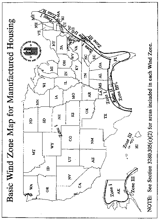
(A) The design wind loads for Exposure C specified in ANSI/ASCE 7-88, “Minimum Design Loads for Buildings and Other Structures,” for a fifty-year recurrence interval, and a design wind speed of 100 mph, as specified for Wind Zone II, or 110 mph, as specified for Wind Zone III (Basic Wind Zone Map); or
(B) The wind pressures specified in the following table:
Table of Design Wind Pressures
| Element | Wind zone II design wind speed 100 MPH | Wind zone III design wind speed 110 MPH |
|---|---|---|
| Anchorage for lateral and vertical stability (See § 3280.306(a)): | ||
| Net Horizontal Drag1 2: | 3 ±39 PSF | 3 ±47 PSF |
| Uplift4: | 5 −27 PSF | −32 PSF |
| Main wind force resisting system: | ||
| Shearwalls, Diaphragms and their Fastening and Anchorage Systems1 2 | ±39 PSF | ±47 PSF |
| Ridge beams and other Main Roof Support Beams (Beams supporting expanding room sections, etc.) | −30 PSF | −36 PSF |
| Components and cladding: | ||
| Roof trusses4 in all areas; trusses shall be doubled within 3′-0′ from each end of the roof | 5 −39 PSF | 5 −47 PSF |
| Exterior roof coverings, sheathing and fastenings4,6,7 in all areas except the following | 5 −39 PSF | 5 −47 PSF |
| Within 3′-0′ from each gable end (overhang at end wall) of the roof or endwall if no overhang is provided4,6,7 | 5 −73 PSF | 5 −89 PSF |
| Within 3′-0′ from the ridge and eave (overhang at sidewall) or sidewall if no eave is provided4,6,7 | 5 −51 PSF | 5 −62 PSF |
| Eaves (Overhangs at Sidewalls)4,6,7 | 5 −51 PSF | 5 −62 PSF |
| Gables (Overhangs at Endwalls)4,6,7 | 5 −73 PSF | 5 −89 PSF |
| Wall studs in sidewalls and endwalls, exterior windows and sliding glass doors (glazing and framing), exterior coverings, sheathing and fastenings8: | ||
| Within 3′-0′ from each corner of the sidewall and endwall | ±48 PSF | ±58 PSF |
| All other areas | ±38 PSF | ±46 PSF |
(iii) One-piece metal roofing capable of resisting the design wind pressures for “Components and Cladding: (Exterior roof coverings)” in the Table for Design Wind Pressures in this section is allowed to be used without structural sheathing, provided the metal roofing is tested using procedures that have been approved by HUD and that meet all requirements of §§ 3280.303(c) and (g) and 3280.401.
(2) Wind loads—zone designations. The Wind Zone and specific wind design load requirements are determined by the fastest basic wind speed (mph) within each Zone and the intended location, based on the Basic Wind Zone Map, as follows:
(i) Wind Zone I. Wind Zone I consists of those areas on the Basic Wind Zone Map that are not identified in paragraphs (c)(2)(ii) or (iii) of this section as being within Wind Zone II or III, respectively.
(ii) Wind Zone II.. ...100 mph. The following areas are deemed to be within Wind Zone II of the Basic Wind Zone Map:
Local governments: The following local governments listed by State (counties, unless specified otherwise):
Alabama: Baldwin and Mobile.
Florida: All counties except those identified in paragraph (c)(1)(i)(C) of this section as within Wind Zone III.
Georgia: Bryan, Camden, Chatham, Glynn, Liberty, McIntosh.
Louisiana: Parishes of Acadia, Allen, Ascension, Assumption, Calcasieu, Cameron, East Baton Rouge, East Feliciana, Evangeline, Iberia, Iberville, Jefferson Davis, LaFayette, Livingston, Pointe Coupee, St. Helena, St. James, St. John the Baptist, St. Landry, St. Martin, St. Tammany, Tangipahoa, Vermillion, Washington, West Baton Rouge, and West Feliciana.
Maine: Hancock and Washington.
Massachusetts: Barnstable, Bristol, Dukes, Nantucket, and Plymouth.
Mississippi: George, Hancock, Harrison, Jackson, Pearl River, and Stone.
North Carolina: Beaufort, Brunswick, Camden, Chowan, Columbus, Craven, Currituck, Jones, New Hanover, Onslow, Pamlico, Pasquotank, Pender, Perquimans, Tyrrell, and Washington.
South Carolina: Beaufort, Berkeley, Charleston, Colleton, Dorchester, Georgetown, Horry, Jasper, and Williamsburg.
Texas: Aransas, Brazoria, Calhoun, Cameron, Chambers, Galveston, Jefferson, Kenedy, Kleberg, Matagorda, Nueces, Orange, Refugio, San Patricio, and Willacy.
Virginia: Cities of Chesapeake, Norfolk, Portsmouth, Princess Anne, and Virginia Beach.
(iii) Wind Zone III.. ...110 mph. The following areas are considered to be within Wind Zone III of the Basic Wind Zone Map:
(A) States and Territories: The entire State of Hawaii, the coastal regions of Alaska (as determined by the 90 mph isotach on the ANSI/ASCE 7-88 map), and all of the U.S. Territories of American Samoa, Guam, Northern Mariana Islands, Puerto Rico, Trust Territory of the Pacific Islands, and the United States Virgin Islands.
(B) Local governments: The following local governments listed by State (counties, unless specified otherwise):
Florida: Broward, Charlotte, Collier, Dade, Franklin, Gulf, Hendry, Lee, Martin, Manatee, Monroe, Palm Beach, Pinellas, and Sarasota.
Louisiana: Parishes of Jefferson, La Fourche, Orleans, Plaquemines, St. Bernard, St. Charles, St. Mary, and Terrabonne.
North Carolina: Carteret, Dare, and Hyde.
(iv) Consideration of local requirements. For areas where wind mapping data or records or the requirements of the State or local authority indicate wind speeds in excess of those identified in this section, the Department may establish, through rulemaking, more stringent requirements for manufactured homes to be installed in such areas.
(3) Snow and roof loads.
(i) Flat, curved and pitched roofs shall be designed to resist the following live loads, applied downward on the horizontal projection as appropriate for the design zone marked on the manufactured home:
| Zone (see Map in § 3280.305(c)(4)) | Pounds per square foot |
|---|---|
| North Zone | 40 |
| Middle Zone | 30 |
| South Zone | 20 |
(A) North Roof Load Zone. The following counties in each of the following states are deemed to be within the North Roof Load Zone:
Maine—Aroostook, Piscataquis, Somerset, Penobscot, Waldo, Knox, Hancock, and Washington.
Alaska—All Counties
(B) Middle Roof Load Zone. The following counties in each of the following states are deemed to be within the Middle Roof Load Zone:
| States | Counties | |||
|---|---|---|---|---|
| South Dakota | Grant | Brookings | Hanson | Lincoln |
| Codington | Miner | Minnehaha | Yankton | |
| Deuel | Lake | Hutchinson | Union | |
| Hamlin | Moody | Turner | Clay | |
| Kingsbury | McCook | |||
| Minnesota | Koochiching | Stearns | Renville | Sibley |
| Itasca | Swift | McLeod | Nicollet | |
| Hubbard | Kandiyohi | Carver | Blue Earth | |
| Cass | Meeker | Dakota | Martin | |
| Crow Wing | Wright | Goodhue | Watonwan | |
| Aitkin | Lac qui Parle | Wabasha | Brown | |
| St. Louis | Chippewa | Winona | Redwood | |
| Lake | Yellow Medicine | Fillmore | Lyon | |
| Cook | Mille Lacs | Mower | Lincoln | |
| Carlton | Kanabec | Olmsted | Pipestone | |
| Pine | Benton | Dodge | Murray | |
| Wadena | Isanti | Rice | Cottonwood | |
| Todd | Sherburne | Steele | Jackson | |
| Morrison | Anoka | Freeborn | Nobles | |
| Douglas | Chisapo | Faribault | Rock | |
| Grant | Washington | Waseca | ||
| Stevens | Hennepin | Le Sueur | ||
| Pope | Ramsey | Scott | ||
| Iowa | Hancock | Mitchell | Hamilton | Buena Vista |
| Lyon | Howard | Webster | Cherokee | |
| Osceola | Chickasaw | Calhoun | Plymouth | |
| Dickinson | Butler | Sac | Sioux | |
| Emmet | Floyd | Ida | O'Brien | |
| Kossuth | Cerro Gordo | Humboldt | Clay | |
| Winnebago | Franklin | Pocahontas | Wright | |
| Worth | Hardin | Palo Alto | ||
| Wisconsin | Douglas | Oconto | Pepin | Lincoln |
| Bayfield | Menominee | Pierce | Oneida | |
| Ashland | Langlade | Dunn | Polk | |
| Iron | Marathon | Eau Claire | Burnett | |
| Vilas | Clark | Chippewa | Washburn | |
| Forest | Jackson | Rusk | Sawyer | |
| Florence | Trempealeau | Barron | Price | |
| Marinette | Buffalo | Taylor | Door | |
| St. Croix | ||||
| Michigan | Houghton | Iron | Presque Isle | Wexford |
| Baraga | Dickinson | Charlevoix | Benzie | |
| Marquette | Menominee | Montmorency | Grand Traverse | |
| Alger | Delta | Alpena | Kalkaska | |
| Luce | Schoolcraft | Alcona | Oscoda | |
| Chippewa | Mackinac | Ogemaw | Otsego | |
| Keweenaw | Cheyboygan | Roscommon | Leelanau | |
| Ontonagon | Emmet | Missaukee | Antrim | |
| Gogebic | Crawford | |||
| New York | St. Lawrence | Herkimer | Onondaga | Genesee |
| Franklin | Lewis | Madison | Orleans | |
| Clinton | Oswego | Cayuga | Niagara | |
| Essex | Jefferson | Seneca | Erie | |
| Hamilton | Oneida | Wayne | Wyoming | |
| Warren | Fulton | Ontario | Monroe | |
| Saratoga | Montgomery | Yates | ||
| Washington | Schenectady | Livingston | ||
| Massachusetts | Essex | |||
| Maine | Franklin | Kennebec | Lincoln | Cumberland |
| Oxford | Androscoggin | Sagadahoc | York | |
| Montana | All Counties | |||
| Idaho | All Counties | |||
| Colorado | All Counties | |||
| Wyoming | All Counties | |||
| Utah | All Counties | |||
| Vermont | Franklin | Orleans | Caledonia | Addison |
| Grand Isle | Essex | Washington | Rutland | |
| Lamoille | Chittenden | Orange | Windsor | |
| New Hampshire | All Counties |
(C) South Roof Load Zone. The states and counties that are not listed for the North Roof Load Zone in paragraph (c)(3)(i)(A) of this section, or the Middle Roof Load Zone in paragraph (c)(3)(i)(B) of this section, are deemed to be within the South Roof Load Zone.
(ii) Consideration of local requirements. For exposures in areas (mountainous or other) where recognized snow records, wind records, or the requirements of the State or local authority indicate significant differences from the loads stated in this paragraph (c)(3), the Department may establish, through rulemaking, more stringent requirements for manufactured homes to be installed in such areas. For snow loads, such requirements must be based on a roof snow load of 0.6 of the ground snow load for areas exposed to wind and a roof snow load of 0.8 of the ground snow load for sheltered areas.
(iii) Eaves and cornices shall be designed for a net uplift pressure of 2.5 times the design uplift wind pressure cited in § 3280.305(c)(1)(i) for Wind Zone I, and for the design pressures cited in § 3280.305(c)(1)(ii) for Wind Zones II and III.
(iv) Skylights must be capable of withstanding roof loads as specified in paragraphs (c)(3)(i) or (c)(3)(ii) of this section. Skylights must be listed and tested in accordance with AAMA 1600/I.S.7-00, 2003, Voluntary Specification for Skylights.
(4) Data plate requirements. The Data Plate posted in the manufactured home (see § 3280.5) shall designate the wind and roof load zones or, if designed for higher loads, the actual design external snow and wind loads for which the home has been designed. The Data Plate shall include reproductions of the Load Zone Maps shown in this paragraph (c)(4), with any related information. The Load Zone Maps shall be not less than either 31⁄2 in. by 21⁄4 in., or one-half the size illustrated in the Code of Federal Regulations.

(d) Design load deflection.
(1) When a structural assembly is subjected to total design live loads, the deflection for structural framing members shall not exceed the following (where L equals the clear span between supports or two times the length of a cantilever):
Floor—L/240
Roof and ceiling—L/180
Headers, beams, and girders (vertical load)—L/180
Walls and partitions—L/180
(2) The allowable eave or cornice deflection for uplift is to be measured at the design uplift load of 9 psf for Wind Zone I, and at the design uplift pressure cited in paragraph (c)(1)(ii) of this section for Wind Zones II and III. The allowable deflection shall be (2 × Lc)/180, where Lc is the measured horizontal eave projection from the wall.
(e) Fastening of structural systems.
(1) Roof framing must be securely fastened to wall framing, walls to floor structure, and floor structure to chassis, to secure and maintain continuity between the floor and chassis in order to resist wind overturning, uplift, and sliding, and to provide continuous load paths for these forces to the foundation or anchorage system. The number and type of fasteners used must be capable of transferring all forces between elements being joined. In multistory construction, each story must be securely fastened to the story above and/or below to provide continuity and resist design loads in this section.
(2) For Wind Zone II and Wind Zone III, roof framing members must be securely fastened at the vertical bearing points to resist design overturning, uplift, and sliding forces. When engineered connectors are not installed, roof framing members must be secured at the vertical bearing points to wall framing members (studs), and wall framing members (studs) must be secured to floor framing members, with 0.016 inch base metal, minimum steel strapping or engineered connectors, or by a combination of 0.016 inch base metal, minimum steel strapping or engineered connectors, and structural-rated wall sheathing that overlaps the roof and floor system if substantiated by structural analysis or by suitable load tests. Steel strapping or engineered connectors are to be installed at a maximum spacing of 24 inches on center in Wind Zone II, and 16 inches on center in Wind Zone III. Exception: Where substantiated by structural analysis or suitable load tests, the 0.016 inch base metal minimum steel strapping or engineered connectors may be omitted at the roof to wall and/or wall to floor connections, when structural rated sheathing that overlaps the roof and wall and/or wall and floor is capable of resisting the applicable design wind loads.
(f) Walls. The walls shall be of sufficient strength to withstand the load requirements as defined in § 3280.305(c) of this part, without exceeding the deflections as specified in § 3280.305(d). The connections between the bearing walls, floor, and roof framework members shall be fabricated in such a manner as to provide support for the material used to enclose the manufactured home and to provide for transfer of all lateral and vertical loads to the floor and chassis.
(1) Except where substantiated by engineering analysis or tests, studs shall not be notched or drilled in the middle one-third of their length.
(2) Interior walls and partitions shall be constructed with structural capacity adequate for the intended purpose and shall be capable of resisting a horizontal load of not less than five pounds per square foot. An allowable stress increase of 1.33 times the permitted published design values may be used in the design of wood framed interior partitions. Finish of walls and partitions shall be securely fastened to wall framing.
(g) Floors.
(1) Floor assemblies shall be designed in accordance with accepted engineering practice standards to support a minimum uniform live load of 40 lb/ft2 plus the dead load of the materials. In addition (but not simultaneously), floors shall be able to support a 200-pound concentrated load on a one-inch diameter disc at the most critical location with a maximum deflection not to exceed one-eighth inch relative to floor framing. Perimeter wood joists of more than six inches depth shall be stabilized against overturning from superimposed loads as follows: at ends by solid blocking not less than two-inch thickness by full depth of joist, or by connecting to a continuous header not less than two-inch thickness and not less than the depth of the joist with connecting devices; at eight-feet maximum intermediate spacing by solid blocking or by wood cross-bridging of not less than one inch by three inches, metal cross-bridging of equal strength, or by other approved methods.
(2) Wood, wood fiber or plywood floors or subfloors in kitchens, bathrooms (including toilet compartments), laundry areas, water heater compartments, and any other areas subject to excessive moisture shall be moisture resistant or shall be made moisture resistant by sealing or by an overlay of nonabsorbent material applied with water-resistant adhesive. Use of one of the following methods would meet this requirement:
(i) Sealing the floor with a water-resistant sealer; or
(ii) Installing an overlay of a non-absorbent floor covering material applied with water-resistant adhesive; or
(iii) Direct application of a water-resistant sealer to the exposed wood floor area when covered with a non-absorbent overlay; or
(iv) The use of a non-absorbent floor covering which may be installed without a continuous application of a water-resistant adhesive or sealant when the floor covering meets the following criteria:
(A) The covering is a continuous membrane with any seams or patches seam bonded or welded to preserve the continuity of the floor covering; and
(B) The floor is protected at all penetrations in these areas by sealing with a compatible water-resistant adhesive or sealant to prevent moisture from migrating under the nonabsorbent floor covering; and
(C) The covering is fastened around the perimeter of the subfloor in accordance with the floor covering manufacturer's instructions; and,
(D) The covering is designed to be installed to prevent moisture penetration without the use of a water-resistant adhesive or sealer except as required in this paragraph (g). The vertical edges of penetrations for plumbing shall be covered with a moisture-resistant adhesive or sealant. The vertical penetrations located under the bottom plates of perimeter walls of rooms, areas, or compartments are not required to be sealed; this does not include walls or partitions within the rooms or areas.
(3) Wood panel products used as floor or subfloor materials on the exterior of the home, such as in recessed entryways, must be rated for exterior exposure and protected from moisture by sealing or applying nonabsorbent overlay with water resistant adhesive.
(4) Carpet or carpet pads shall not be installed under concealed spaces subject to excessive moisture, such as plumbing fixture spaces, floor areas under installed laundry equipment. Carpet may be installed in laundry space provided:
(i) The appliances are not provided;
(ii) The conditions of paragraph (g)(2) of this section are followed; and
(iii) Instructions are provided to remove carpet when appliances are installed.
(5) Except where substantiated by engineering analysis or tests:
(i) Notches on the ends of joists shall not exceed one-fourth the joist depth.
(ii) Holes bored in joists shall not be within 2 inches of the top or bottom of the joist, and the diameter of any such hole shall not exceed one-third the depth of the joist.
(iii) Notches in the top or bottom of the joists shall not exceed one-sixth the depth and shall not be located in the middle third of the span.
(6) Bottom board material (with or without patches) must meet or exceed the level of 48 inch-pounds of puncture resistance as tested by the Beach Puncture Test in accordance with Standard Test Methods for Puncture and Stiffness of Paperboard, and Corrugated and Solid Fiberboard, ASTM D781-1968 (Reapproved 1973) (incorporated by reference, see § 3280.4). The material must be suitable for patches and the patch life must be equivalent to the material life. Patch installation instruction must be included in the manufactured home manufacturer's instructions. The bottom board material must be tight fitted against all penetrations.
(h) Roofs.
(1) Roofs shall be of sufficient strength to withstand the load requirements as defined in § 3280.305 (b) and (c) without exceeding the deflections specified in § 3280.305(d). The connections between roof framework members and bearing walls shall be fabricated in such a manner to provide for the transfer of design vertical and horizontal loads to the bearing walls and to resist uplift forces.
(2) Roofing membranes shall be of sufficient rigidity to prevent deflection which would permit ponding of water or separation of seams due to wind, snow, ice, erection or transportation forces.
(3) Cutting of roof framework members for passage of electrical, plumbing or mechanical systems shall not be allowed except where substantiated by engineering analysis.
(4) All roof penetrations for electrical, plumbing or mechanical systems shall be properly flashed and sealed. In addition, where a metal roof membrane is penetrated, a wood backer shall be installed. The backer plate shall be not less than 5⁄16 inch plywood, with exterior glues, secured to the roof framing system beneath the metal roof, and shall be of a size to assure that all screws securing the flashing are held by the backer plate.
(5) Portions of roof assemblies, including, but not limited to, dormers, gables, crickets, hinged roof sections, sheathing, roof coverings, underlayments, flashings, and eaves and overhangs are permitted to be assembled and installed on site in accordance with 24 CFR part 3282, subpart M, provided that the requirements in paragraphs (h)(5)(i) through (iv) of this section are met.
(i) Approved installation instructions must be provided that include requirements for the following items:
(A) Materials, installation, and structural connections complying with this section;
(B) Installation and fastening of sheathing and roof coverings;
(C) Installation of appliance vent systems in accordance with § 3280.710;
(D) Installation of plumbing vents as required by § 3280.611; and
(E) Installation of attic ventilation in accordance with § 3280.504(c).
(ii) The installation instructions specified in paragraph (h)(5)(i) of this section must include drawings, details, and instructions as necessary to assure that the on-site work complies with the approved design.
(iii) The installation instructions specified in paragraph (h)(5)(i) of this section must provide for inspection of the work at the installation site. As necessary to ensure conformance, inspection panels may be required, or inspections may need to occur in stages that assure inspections are performed before any work is concealed. Such inspection procedures shall be addressed in the approved installation instructions.
(iv) Temporary weather protection must be provided per § 3280.307(e).
(i) Frame construction. The frame shall be capable of transmitting all design loads to stabilizing devices without exceeding the allowable load and deflections of this section. The frame shall also be capable of withstanding the effects of transportation shock and vibration without degradation as required by subpart J.
(1) [Reserved]
(2) Protection of metal frames against corrosion. Metal frames shall be made corrosion resistant or protected against corrosion. Metal frames may be protected against corrosion by painting.
(j) Welded connections.
(1) All welds must be made in accordance with the applicable provisions of the Specification for Structural Steel Buildings, Allowable Stress Design and Plastic Design, AISC-S335, 1989; the Specification for the Design of Cold-Formed Steel Structural Members, AISI, 1996; and the Specification for the Design of Cold-Formed Stainless Steel Structural Members, SEI/ASCE 8-02, 2002.
(2) Regardless of the provisions of any reference standard contained in this subpart, deposits of weld slag or flux shall be required to be removed only from welded joints at the following locations:
(i) Drawbar and coupling mechanisms;
(ii) Main member splices, and
(iii) Spring hanger to main member connections.
(k) Attics.
(1) For roofs with slopes 7:12 or greater, the area of the attic floor that meets the ceiling-height/living-space requirements of these construction and safety standards must be designed to resist a minimum design live load of 40 pounds per square foot (psf) in accordance with paragraph (g) of this section.
(2) For roofs with slopes less than 7:12 that contain an attic area or for portions of roofs with slopes 7:12 or greater that do meet the ceiling height/living space requirements of the standards, the attic floor must be designed for a storage live load of 20 pounds per square foot (psf).
[40 FR 58752, Dec. 18, 1975. Redesignated at 44 FR 20679, Apr. 6, 1979, as amended at 44 FR 66195, Nov. 19, 1979; 52 FR 4582, Feb. 12, 1987; 58 FR 55006, Oct. 25, 1993; 59 FR 2469, Jan. 14, 1994; 59 FR 15113, 15114, Mar. 31, 1994; 62 FR 54547, Oct. 20, 1997; 70 FR 72043, Nov. 30, 2005; 71 FR 19638, Apr. 17, 2006; 78 FR 73983, Dec. 9, 2013; 80 FR 53727, Sept. 8, 2015; 86 FR 2520, Jan. 12, 2021; 86 FR 10457, Feb. 22, 2021]
§ 3280.306 Windstorm protection.
(a) Provisions for support and anchoring systems. Each manufactured home shall have provisions for support/anchoring or foundation systems that, when properly designed and installed, will resist overturning and lateral movement (sliding) of the manufactured home as imposed by the respective design loads. For Wind Zone I, the design wind loads to be used for calculating resistance to overturning and lateral movement shall be the simultaneous application of the wind loads indicated in § 3280.305(c)(1)(i), increased by a factor of 1.5. The 1.5 factor of safety for Wind Zone I is also to be applied simultaneously to both the vertical building projection, as horizontal wind load, and across the surface of the full roof structure, as uplift loading. For Wind Zones II and III, the resistance shall be determined by the simultaneous application of the horizontal drag and uplift wind loads, in accordance with § 3280.305(c)(1)(ii). The basic allowable stresses of materials required to resist overturning and lateral movement shall not be increased in the design and proportioning of these members. No additional shape or location factors need to be applied in the design of the tiedown system. The dead load of the structure may be used to resist these wind loading effects in all Wind Zones.
(1) The provisions of this section shall be followed and the support and anchoring systems shall be designed by a Registered Professional Engineer or Architect.
(2) The manufacturer of each manufactured home is required to make provision for the support and anchoring systems but is not required to provide the anchoring equipment or stabilizing devices. When the manufacturer's installation instructions provide for the main frame structure to be used as the points for connection of diagonal ties, no specific connecting devices need be provided on the main frame structure.
(b) Contents of instructions.
(1) The manufacturer must provide printed instructions with each manufactured home that specify the location and required capacity of stabilizing devices on which the home's design is based. The manufacturer must identify by paint, label, decal stencil, or other means: the location of each column support pier location required along the marriage line(s) of multi-section manufactured homes; each pier location required along the perimeter of the home; each required shear wall pier support; and any other special pier support locations specified in the manufacturer's printed instructions. Such identifications must be visible after the home is installed. The manufacturer must provide drawings and specifications, certified by a registered professional engineer or architect, that indicate at least one acceptable system of anchoring, including the details or required straps or cables, their end connections, and all other devices needed to transfer the wind loads from the manufactured home to an anchoring or foundation system.
(2) For anchoring systems, the instructions shall indicate:
(i) The minimum anchor capacity required;
(ii) That anchors should be certified by a professional engineer, architect, or a nationally recognized testing laboratory as to their resistance, based on the maximum angle of diagonal tie and/or vertical tie loading (see paragraph (c)(3) of this section) and angle of anchor installation, and type of soil in which the anchor is to be installed;
(iii) That ground anchors are to be embedded below the frost line, unless the foundation system is frost-protected in accordance with §§ 3285.312(b) and 3285.404 of the Model Manufactured Home Installation Standards in this chapter.
(iv) That ground anchors must be installed to their full depth, and stabilizer plates must be installed in accordance with the ground anchor listing or certification to provide required resistance to overturning and sliding.
(v) That anchoring equipment should be certified by a registered professional engineer or architect to resist these specified forces in accordance with testing procedures in ASTM D3953-97, Standard Specification for Strapping, Flat Steel and Seals (incorporated by reference, see § 3280.4).
(c) Design criteria. The provisions made for anchoring systems shall be based on the following design criteria for manufactured homes.
(1) The minimum number of ties provided per side of each home shall resist design wind loads required in § 3280.305(c)(1).
(2) Ties shall be as evenly spaced as practicable along the length of the manufactured home, with not more than two (2) feet open-end spacing on each end.
(3) Vertical ties or straps shall be positioned at studs. Where a vertical tie and a diagonal tie are located at the same place, both ties may be connected to a single anchor, provided that the anchor used is capable of carrying both loadings, simultaneously.
(4) Add-on sections of expandable manufactured homes shall have provisions for vertical ties at the exposed ends.
(d) Requirements for ties. Manufactured homes in Wind Zone I require only diagonal ties. These ties shall be placed along the main frame and below the outer side walls. All manufactured homes designed to be located in Wind Zones II and III shall have a vertical tie installed at each diagonal tie location.
(e) Protection requirements. Protection shall be provided at sharp corners where the anchoring system requires the use of external straps or cables. Protection shall also be provided to minimize damage to siding by the cable or strap.
(f) Anchoring equipment—load resistance. Anchoring equipment shall be capable of resisting an allowable working load equal to or exceeding 3,150 pounds and shall be capable of withstanding a 50 percent overload (4,725 pounds total) without failure of either the anchoring equipment or the attachment point on the manufactured home.
(g) Anchoring equipment—weatherization. Anchoring equipment exposed to weathering shall have a resistance to weather deterioration at least equivalent to that provided by a coating of zinc on steel of not less than 0.30 ounces per square foot of surface coated, and in accordance with the following:
(1) Slit or cut edges of zinc-coated steel strapping do not need to be zinc coated.
(2) Type 1, Finish B, Grade 1 steel strapping, 11⁄4 inches wide and 0.035 inches in thickness, certified by a registered professional engineer or architect as conforming with ASTM D3953-97, Standard Specification for Strapping, Flat Steel and Seals (incorporated by reference, see § 3280.4).
[40 FR 58752, Dec. 18, 1975. Redesignated at 44 FR 20679, Apr. 6, 1979, as amended at 52 FR 4583, Feb. 12, 1987; 59 FR 2473, Jan. 14, 1994; 70 FR 72045, Nov. 30, 2005; 72 FR 59362, Oct. 19, 2007; 78 FR 73983, Dec. 9, 2013]
§ 3280.307 Resistance to elements and use.
(a) Exterior coverings shall be of moisture and weather resistive materials attached with corrosion resistant fasteners to resist wind, snow and rain. Metal coverings and exposed metal structural members shall be of corrosion resistant materials or shall be protected to resist corrosion. All joints between portions of the exterior covering shall be designed, and assembled to protect against the infiltration of air and water, except for any designed ventilation of wall or roof cavity.
(b) Joints between dissimilar materials and joints between exterior coverings and frames of openings shall be protected with a compatible sealant suitable to resist infiltration of air or water.
(c) Where adjoining materials or assemblies of materials are of such nature that separation can occur due to expansion, contraction, wind loads or other loads induced by erection or transportation, sealants shall be of a type that maintains protection against infiltration or penetration by air, moisture or vermin.
(d) Exterior surfaces shall be sealed to resist the entrance of rodents.
(e) Multi-section and attached manufactured homes (see subpart K of this part) are not required to comply with the factory installation of weather-resistant exterior finishes for those areas left open for field connection of the sections provided the following conditions are satisfied:
(1) Temporary weather protection for exposed, unprotected construction is provided in accordance with methods to be included in the approved design.
(2) Methods for on-site completion and finishing of these elements are included in the approved design.
(3) Complete installation instructions and the required materials for finishing these elements are provided.
[40 FR 58752, Dec. 18, 1975, as amended at 86 FR 2520, Jan. 12, 2021]
§ 3280.308 Formaldehyde emission controls for composite wood products
(a) Definitions. For purposes of this section, the definitions found in 40 CFR 770.3 apply.
(b) Formaldehyde emission levels. The following maximum formaldehyde emission standards apply whether the composite wood product is in the form of a panel or is incorporated into a component part or finished good:
(1) For hardwood plywood made with a veneer core or composite core, the maximum level is 0.05 parts per million (ppm) of formaldehyde;
(2) For medium density fiberboard, the maximum level is 0.11 ppm of formaldehyde;
(3) For thin medium density fiberboard, the maximum level is 0.13 ppm of formaldehyde; and
(4) For particleboard, the maximum level is 0.09 ppm of formaldehyde.
(c) Product certification and continuing qualification. Only certified composite wood products whether in the form of panels or incorporated into component parts or finished goods, are permitted to be used in manufactured homes sold, supplied, offered for sale, or manufactured in or imported into the United States, consistent with Environmental Protection Agency (EPA) product testing requirements at 40 CFR 770.15. See § 3280.406 for testing requirements for product certification and testing requirements for continuing qualification of formaldehyde emission levels.
(d) Panel label. Manufactured homes must use panels or bundles of panels that are labeled by a panel producer consistent with the labeling requirements at 40 CFR 770.45.
(e) Finished good certification label. Each manufactured home must be provided with a finished good certification label indicating that the home has been produced with composite wood products, or finished goods that contain composite wood products, that comply with the formaldehyde emission requirements of this part and 40 CFR part 770, consistent with § 3280.5(i).
(f) Non-complying lots. Composite wood products from non-complying lots (i.e., lots that exceed the applicable formaldehyde ppm) are not certified composite wood products and may not be used in manufactured homes except in accordance with 40 CFR 770.22.
(g) Stockpiling. The use of stockpiled inventory of composite wood products, whether in the form of panels or incorporated into component parts or finished goods, in manufactured homes, is prohibited in accordance with EPA regulations at 40 CFR 770.12(b) through (d).
(h) Third party certification. All composite wood products in paragraph (b) of this section must be certified by an agency or organization that has been recognized to participate in the EPA Toxic Substances Control Act (TSCA) Title VI Third Party Certification Program.
[85 FR 5566, Jan. 31, 2020]